Ford Escape: Engine / General Procedures - Balance Shaft Backlash
Special Tool(s) / General Equipment
.jpg) |
100-002
(TOOL-4201-C)
Holding Fixture with Dial Indicator Gauge |
.jpg) |
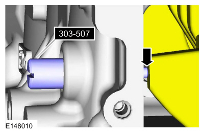
303-507 Timing Peg, Crankshaft TDC TKIT-2001N-FLM TKIT-2001N-ROW |
Check
-
- Install Special Service Tool: 303-507 Timing Peg, Crankshaft TDC.
-
Rotate the crankshaft slowly clockwise until the crankshaft balance
weight is up against the Crankshaft TDC Timing Peg. The engine is now at
TDC .
 |
-
Mark the balancer unit and shafts on the top for reference that the balancer unit is at TDC .
.jpg) |
-
NOTE: Due to the precision interior construction of the balancer unit, it should not be disassembled.
 |
-
Remove the adjustment shims from the seat faces of the balancer unit.
-
NOTE: Visually inspect the balancer unit gear for damage and verify that the shaft turns smoothly. If there is any damage or malfunction, replace the balancer unit.
Install the master adjustment shims (No. 50) on the seat faces of the balancer unit.
-
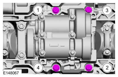
With the balancer unit shaft marks at the TDC
position, slowly install the balancer unit to the cylinder block to
avoid interference between the crankshaft drive gear and the balancer
unit driven gear.
.jpg) |
-
Torque:
Stage 1: 18 lb.ft (25 Nm)
Stage 2: 38 lb.ft (52 Nm)
 |
-
- Remove Special Service Tool: 303-507 Timing Peg, Crankshaft TDC.
-
Rotate the crankshaft to confirm that there are no
meshing problems between the balancer unit gear and the crankshaft gear.
.jpg) |
-
- Install Special Service Tool: 303-507 Timing Peg, Crankshaft TDC.
-
Rotate the crankshaft slowly clockwise until the crankshaft balance
weight is up against the Crankshaft TDC Timing Peg. The engine is now at
TDC .
- Remove Special Service Tool: 303-507 Timing Peg, Crankshaft TDC.
|
-
NOTE: Measure the backlash and verify that it is within specified range at all of the following 6 positions: 10 degrees, 30 degrees, 100 degrees, 190 degrees, 210 degrees and 280 degrees. It will be necessary to reset the measuring equipment between measurements.
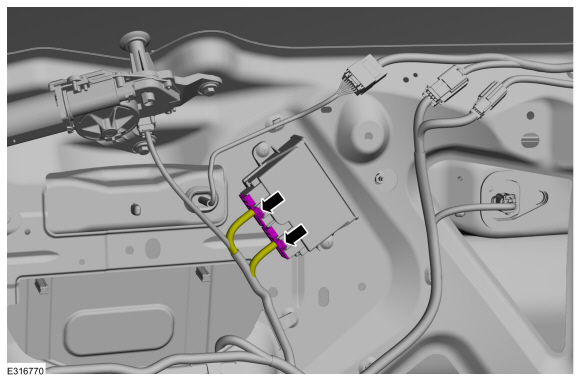
NOTE: The measurement must be taken with the Dial Indicator Gauge with Holding Fixture, a 5-mm Allen wrench and worm clamp set up as shown. Mark the Allen wrench with a file 80 mm (3.149 in) above the driven gear shaft center. Make sure the worm clamp and Allen wrench are not touching the balance shaft housing.
NOTE: For an accurate measurement while measuring the gear backlash, insert a screwdriver as shown into the crankshaft No. 1 crankweight area and set both the rotation and the thrust direction with the screwdriver, using a prying action as shown.
-
Position as shown. Measure the gear backlash.
Use Special Service Tool: 100-002 (TOOL-4201-C) Holding Fixture with Dial Indicator Gauge.
-
Position the Dial Indicator Gauge with Holding
Fixture (1) on the Allen wrench 80 mm (3.149 in) above the driven gear
shaft center (2) on the balancer unit.
-
Rotate the crankshaft clockwise and measure the
backlash at all of the following 6 positions: 10 degrees, 30 degrees,
100 degrees, 190 degrees, 210 degrees and 280 degrees.
-
Position as shown. Measure the gear backlash.
.jpg) |
-
Using the backlash measurement, select the proper shims from the Adjustment Shim Selection Table.
-
Backlash
-
Selection shim (No.)
-
Shim thickness
-
Backlash
.jpg) |
-
-
Remove the balancer unit from the cylinder block.
-
Install the selected adjustment shims on the seat faces of the balancer unit.
-
Remove the balancer unit from the cylinder block.
-
- Install Special Service Tool: 303-507 Timing Peg, Crankshaft TDC.
-
Rotate the crankshaft slowly clockwise until the crankshaft balance
weight is up against the Crankshaft TDC Timing Peg. The engine is now at
TDC .
|
-
With the balancer unit shaft marks at the TDC
position, slowly install the balancer unit to the cylinder block to
avoid interference between the crankshaft drive gear and the balancer
unit driven gear.
|
-
Torque:
Stage 1: 18 lb.ft (25 Nm)
Stage 2: 38 lb.ft (52 Nm)
|
- Remove Special Service Tool: 303-507 Timing Peg, Crankshaft TDC.
|
-
NOTE: Measure the backlash and verify that it is within specified range at all of the following 6 positions: 10 degrees, 30 degrees, 100 degrees, 190 degrees, 210 degrees and 280 degrees. It will be necessary to reset the measuring equipment between measurements.
NOTE: The measurement must be taken with the Dial Indicator Gauge with Holding Fixture, a 5-mm Allen wrench and worm clamp set up as shown. Mark the Allen wrench with a file 80 mm (3.149 in) above the driven gear shaft center. Make sure the worm clamp and Allen wrench are not touching the balance shaft housing.
NOTE: For an accurate measurement while measuring the gear backlash, insert a screwdriver as shown into the crankshaft No. 1 crankweight area and set both the rotation and the thrust direction with the screwdriver, using a prying action as shown.
-
Position as shown. Measure the gear backlash.
Use Special Service Tool: 100-002 (TOOL-4201-C) Holding Fixture with Dial Indicator Gauge.
-
Position the Dial Indicator Gauge with Holding
Fixture (1) on the Allen wrench 80 mm (3.149 in) above the driven gear
shaft center (2) on the balancer unit.
-
Rotate the crankshaft clockwise and measure the
backlash at all of the following 6 positions: 10 degrees, 30 degrees,
100 degrees, 190 degrees, 210 degrees and 280 degrees.
-
If the backlash exceeds the specified range of 0.005
to 0.101 mm (0.00019 to 0.0039 in), install a new balancer unit and
repeat the procedure.
-
Position as shown. Measure the gear backlash.
|
 Diagnosis and Testing - Engine
For gas engine mechanical diagnosis and testing, REFER to: Engine (303-00 Engine System - General Information, Diagnosis and Testing). For DTC (Diagnostic Trouble Code) related concerns, REFER to the Master DTC Chart...
 General Procedures - Valve Clearance Adjustment
Special Tool(s) /
General Equipment
Feeler Gauge
Check
Refer to: Valve Cover (303-01C Engine, Removal and Installation).
NOTE:
Turn the engine clockwise only, and only use the crankshaft bolt...
Other information:
Ford Escape 2020-2026 Service Manual: Diagnosis and Testing - Intake Air Pressure and Temperature
Diagnostic Trouble Code (DTC) Chart Diagnostics in this manual assume a certain skill level and knowledge of Ford-specific diagnostic practices.REFER to: Diagnostic Methods (100-00 General Information, Description and Operation). Module DTC Description Action PCM P007A:00 Charge Air Cooler Temperature Sensor Circuit (Bank 1): No Sub Type Information GO to Pinpoint Test DN P..
Ford Escape 2020-2026 Service Manual: General Procedures - Power Roof Opening Panel Initialization
Initialization WARNING: Keep objects and body parts clear of the glass panel when carrying out the initialization procedure. During the initialization procedure, the glass panel closes with high force and cannot detect objects in its path. Failure to follow this instruction may result in serious personal injury. NOTE: The roof opening panel motor must be initialized when repa..
Categories
- Manuals Home
- 4th Generation Ford Escape Owners Manual
- 4th Generation Ford Escape Service Manual
- Description and Operation - Identification Codes
- Switching the Rear Window Wiper On and Off. Reverse Wipe
- Adjusting the Headlamps
- New on site
- Most important about car
Adjusting the Seatbelts During Pregnancy
WARNING: Always ride and drive with your seatback upright and properly fasten your seatbelt. Fit the lap portion of the seatbelt snugly and low across the hips. Position the shoulder portion of the seatbelt across your chest. Pregnant women must follow this practice. See the following figure.
