Ford Escape 2020-2026 Service Manual / Powertrain / Engine / Fuel Charging and Controls / Removal and Installation - Port Injection Fuel Rail
Ford Escape: Fuel Charging and Controls / Removal and Installation - Port Injection Fuel Rail
Removal
-
Release the fuel system pressure.
Refer to: Fuel System Pressure Release (310-00C Fuel System - General Information, General Procedures).
-
Disconnect the battery.
Refer to: Battery Disconnect and Connect (414-01 Battery, Mounting and Cables, General Procedures).
-
Remove the nut, release the engine appearance cover from the ball-studs, then remove the cover.
.jpg) |
-
Disconnect the spring lock coupling.
Refer to: Spring Lock Couplings (310-00C Fuel System - General Information, General Procedures).
.jpg) |
-
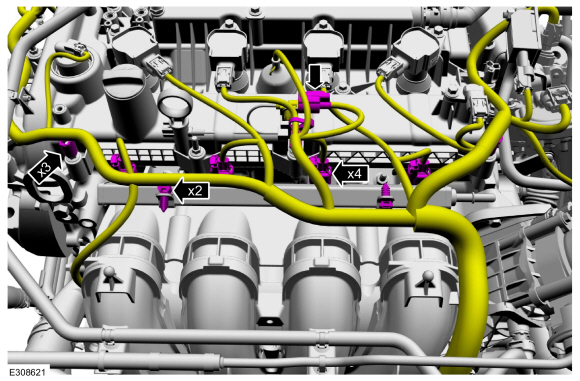
Disconnect the wiring harness retainers from the fuel
rail, detach the wiring harness retainers, disconnect the ignition
interference capacitor electrical connector, then disconnect the fuel
injector electrical connectors.
 |
-
NOTE: Use compressed air and remove any dirt or foreign material from the cylinder head, block and general surrounding area of the fuel rail and injectors.
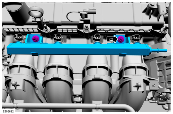
Remove the fuel rail studbolts, then remove the fuel rail.
 |
-
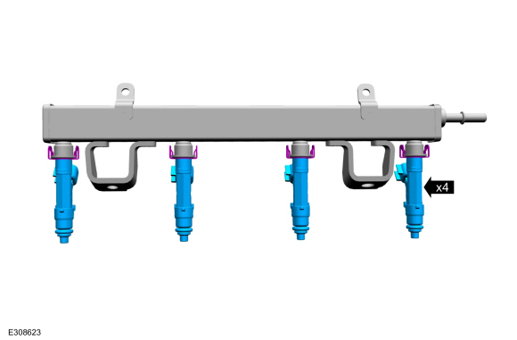
Remove the fuel injectors from the fuel rail.
 |
-
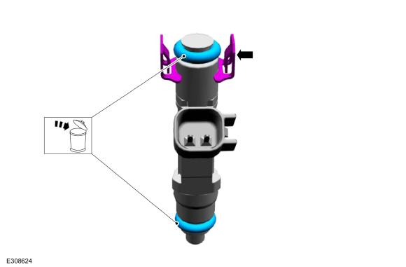
Remove and discard the fuel injector O-ring seals. Remove the fuel injector clips.
 |
Installation
-
NOTICE: Do not reuse the O-ring seals.
NOTE: Make sure that new fuel injector O-ring seals are installed.
Install the new fuel injector O-ring seals and the fuel injector clips. Lubricate the new O-rings with clean engine oil.
Refer to: Specifications (303-01C Engine, Specifications).
.jpg) |
-
Install the fuel injectors to the fuel rail.
|
-
Install the fuel rail, then install and tighten the studbolts.
Torque:
Stage 1: Tighten to: : 18 lb.ft (25 Nm)
Stage 2: Tighten an additional: : 30°
|
-
Connect the fuel injector electrical connectors, connect
the ignition interference capacitor electrical connector, attach the
wiring harness retainers, then connect the wiring harness retainers to
the fuel rail.
|
-
Connect the spring lock coupling.
Refer to: Spring Lock Couplings (310-00C Fuel System - General Information, General Procedures).
|
-
Install the engine appearance cover to the ball-studs, then install and tighten the nut.
Torque: 97 lb.in (11 Nm)
|
-
Connect the battery.
Refer to: Battery Disconnect and Connect (414-01 Battery, Mounting and Cables, General Procedures).
-
Pressurize the fuel system.
Refer to: Fuel System Pressure Release (310-00C Fuel System - General Information, General Procedures).
 Removal and Installation - Fuel Pump Driver Module (FPDM)
Removal
Position the second row left seat back all the way
forward, then raise front of the rear load floor up and out of the way.
Raise the left front corner of the left load compartment floor support up and out of the way...
 Removal and Installation - Throttle Body
Removal
Remove the air cleaner and the air cleaner outlet pipe.
Refer to: Air Cleaner (303-12C Intake Air Distribution and Filtering, Removal and Installation)...
Other information:
Ford Escape 2020-2026 Service Manual: Removal and Installation - Front Bumper
Special Tool(s) / General Equipment Interior Trim Remover Removal NOTE: Removal steps in this procedure may contain installation details. Remove the front bumper cover. Refer to: Front Bumper Cover (501-19 Bumpers, Removal and Installation)...
Ford Escape 2020-2026 Owners Manual: Electromagnetic Compatibility
WARNING: Do not place objects or mount equipment on or near the airbag cover, on the side of the front or rear seatbacks, or in areas that may come into contact with a deploying airbag. Failure to follow these instructions may increase the risk of personal injury in the event of a crash...
Categories
- Manuals Home
- 4th Generation Ford Escape Owners Manual
- 4th Generation Ford Escape Service Manual
- Description and Operation - Identification Codes
- Drive Modes
- Opening and Closing the Hood
- New on site
- Most important about car
Push Button Ignition Switch

Switching the Ignition Off
When the ignition is on or in accessory mode, press the push button ignition switch once without your foot on the brake pedal.
Copyright © 2026 www.fordescape4.com