Ford Escape: Engine / Assembly - Engine
Special Tool(s) /
General Equipment
.jpg) |
100-002
(TOOL-4201-C)
Holding Fixture with Dial Indicator Gauge |
 |
205-153
(T80T-4000-W)
Handle |
 |
303-096
(T74P-6150-A)
Installer, Camshaft Front Oil Seal
TKIT-2009TC-F |
 |
303-1247
VCT Spark Plug Tube Seal Remover and Installer
TKIT-2006UF-FLM
TKIT-2006UF-ROW |
 |
303-1416
Tool, Crank Damper Holding
TKIT-2008ET-FLM |
 |
303-1699
Tool, Crank Sensor Alignment |
 |
303-328
(T88P-6701-B1)
Replacer, Rear Seal
TKIT-1988-FLM
TKIT-1988-F
TKIT-1988-LM |
 |
303-465
Tool, Camshaft Align Timing
TKIT-1994-LMH/MH2
TKIT-1994-FH/FMH/FLMH |
 |
303-507
Timing Peg, Crankshaft TDC
TKIT-2001N-FLM
TKIT-2001N-ROW |
| Mounting Stand |
| Hose Clamp Remover/Installer |
| Round-Ended Steel Rule |
| Piston Ring Compressor |
Materials
| Name |
Specification |
Motorcraft® High Performance Engine RTV Silicone
TA-357 |
WSE-M4G323-A6
|
Motorcraft® Metal Surface Prep Wipes
ZC-31-B |
-
|
Motorcraft® Silicone Brake Caliper Grease and Dielectric Compound
XG-3-A |
ESA-M1C200-A
ESE-M1C171-A
|
NOTICE:
Do not loosen or remove the crankshaft pulley bolt without first
installing the special tools as instructed in this procedure. The
crankshaft pulley and the crankshaft timing sprocket are not keyed to
the crankshaft. The crankshaft, the crankshaft sprocket and the pulley
are fitted together by friction. For that reason, the crankshaft
sprocket is also unfastened if the pulley bolt is loosened. Before any
repair requiring loosening or removal of the crankshaft pulley bolt, the
crankshaft and camshafts must be locked in place by the special service
tools, otherwise severe engine damage can occur.
NOTICE:
During engine repair procedures, cleanliness is extremely
important. All parts must be thoroughly cleaned and any foreign
material, including any material created while cleaning gasket surfaces,
that enters the oil passages, coolant passages or the oil pan, can
cause engine failure.
NOTE:
Assembly of the engine requires various inspections/measurements
of the engine components (engine block, crankshaft, connecting rods,
pistons and piston rings). These inspections/measurements will aid in
determining if the engine components will require replacement. For
additional information, refer to Section 303-00.
NOTE:
For additional information, refer to the exploded views in Description and Operation in this section.
-
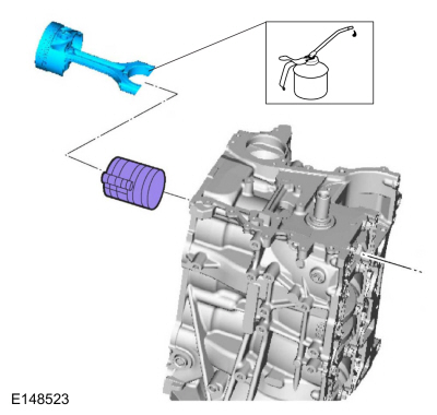
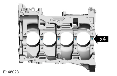
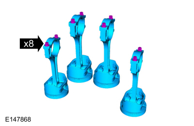
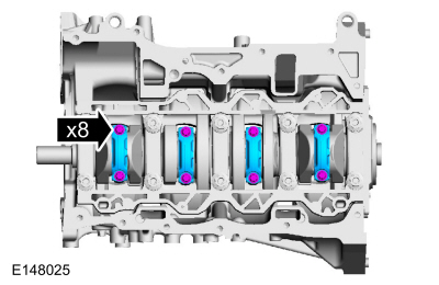
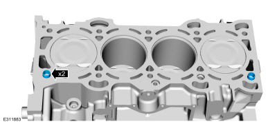
NOTE:
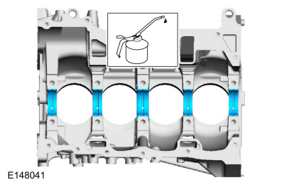
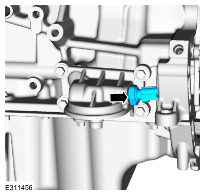
If the oil squirters are being reused, they must be installed in the same location as marked during disassembly.
NOTE:
The front bulkhead does not have an oil squirter.
Install the oil squirters.
Torque:
35 lb.in (4 Nm)
-
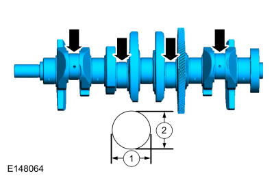
Measure each of the crankshaft main bearing journal
diameters in at least 2 directions and record the smallest diameter for
each journal.
-
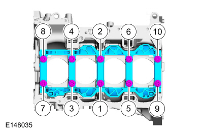
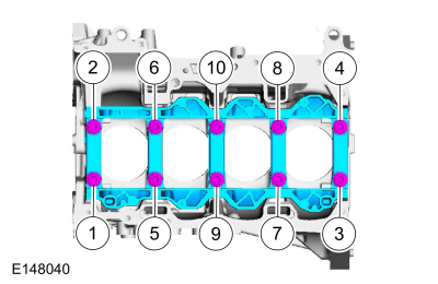
Position the main bearing beam in the engine block with the
main bearing beam mounted flush with the rear face of the engine block
and install the original main bearing beam bolts finger tight.
-
Tighten the bolts in sequence shown in 3 stages.
Torque:
Stage 1:
44 lb.in (5 Nm)
Stage 2:
18 lb.ft (25 Nm)
Stage 3:
90°
-
Measure each crankshaft block main bearing bore diameter.
-
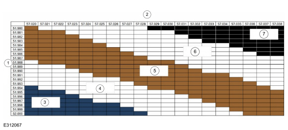
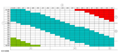
NOTE:
The bearing color corresponds to the number marked on the bearing.
Using the chart, select the correct grade main bearings.
-
Crankshaft journal diameter
-
Cylinder block bore diameter
-
Upper Bearing Blue: 1 / Lower Bearing Blue: 1
-
Upper Bearing Blue: 2 / Lower Bearing Brown: 1
-
Upper Bearing Brown: 2 / Lower Bearing Brown: 2
-
Upper Bearing Black: 3 / Lower Bearing Brown: 2
-
Upper Bearing Black: 3 / Lower Bearing Black: 3
-
NOTE:
The rod cap installation must keep the same orientation as marked during disassembly or engine damage may occur.
Using the original connecting rod cap bolts, install the connecting caps and the bolts. Tighten in 3 stages.
Torque:
Stage 1:
89 lb.in (10 Nm)
Stage 2:
21 lb.ft (29 Nm)
Stage 3:
90°
-
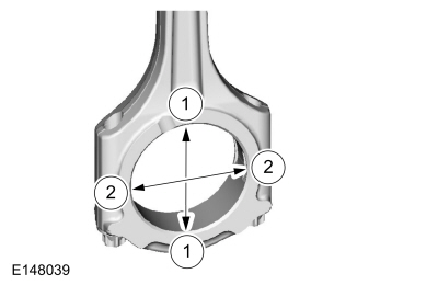
Measure the connecting rod large end bore in 2 directions.
Record the smallest measurement for each connecting rod. Remove the
bolts and the connecting rod cap. Discard the connecting rod cap bolts.
-
Measure each of the crankshaft connecting rod bearing
journal diameters in at least 2 directions. Record the smallest
measurement for each connecting rod journal.
-
NOTE:
The bearing color corresponds to the number marked on the bearing.
Using the chart, select the correct grade connecting rod bearings.
-
Crankshaft journal diameter
-
Connecting rod diameter
-
Upper Bearing Green: 1 / Lower Bearing Green: 1
-
Upper Bearing Blue: 2 / Lower Bearing Green: 1
-
Upper Bearing Blue: 2 / Lower Bearing Blue: 2
-
Upper Bearing Red: 3 / Lower Bearing Blue: 2
-
Upper Bearing Red: 3 / Lower Bearing Red: 3
-
-
Remove the bolts in the sequence shown and the main bearing beam.
-
Discard the main bearing beam bolts.
-
NOTE:
Before assembling the cylinder block, all sealing
surfaces must be free of chips, dirt, paint and foreign material. Also,
make sure the coolant and oil passages are clear.
NOTE:
If reusing the crankshaft main bearings, install them in
their original positions and orientation as noted during disassembly.
NOTE:
The center bulkhead is the thrust bearing.
Lubricate with clean engine oil and install the upper crankshaft main bearings.
-
NOTE:
If reusing the crankshaft main bearings, install them in
their original positions and orientation as noted during disassembly.
Lubricate with clean engine oil and install the lower crankshaft main bearings.
-
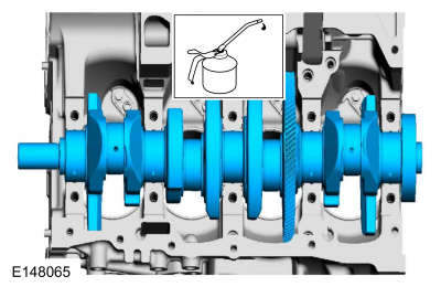
NOTE:
Lubricate the journals on the crankshaft with clean engine oil.
Lubricate with clean engine oil and install the crankshaft.
-
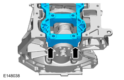
Lubricate the main bearing beam clean engine oil.
-
Install the main bearing beam flush.
-
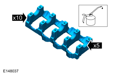
NOTE:
Lubricate the main bearing beam bolts threads and under the bolt heads with clean engine oil.
NOTE:
Position the crankshaft to the rear of the cylinder
block, then position the crankshaft to the front of the cylinder block
before tightening the main bearing beam bolts.
Install the new bolts and tighten in sequence shown in 3 stages.
Torque:
Stage 1:
44 lb.in (5 Nm)
Stage 2:
18 lb.ft (25 Nm)
Stage 3:
90°
-
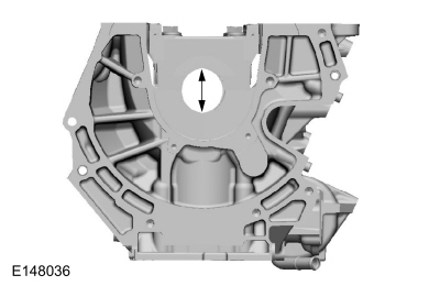
-
Position the crankshaft to the rear of the cylinder block.
-
Zero the Dial Indicator Gauge with Holding Fixture.
Use Special Service Tool: 100-002
(TOOL-4201-C)
Holding Fixture with Dial Indicator Gauge.
-
Move the crankshaft to the front of the cylinder block. Note and record the crankshaft end play.
-
Acceptable crankshaft end play is 0.22-0.45 mm
(0.008-0.018 in). If the crankshaft end play exceeds the specified
range, install new parts as necessary.
-
NOTE:
If reusing the connecting rod bearings, install them in
their original positions and orientation as noted during disassembly.
Lubricate with clean engine oil and install the connecting rod bearings.
-
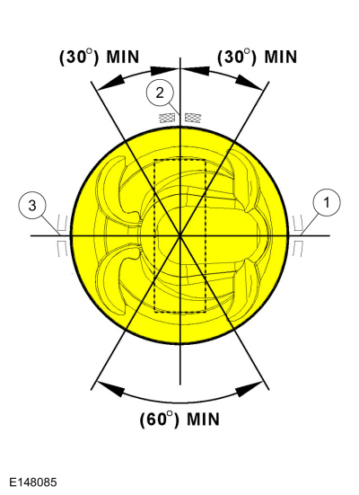
NOTE:
The piston compression upper and lower rings should be
installed with the paint mark on the outside diameter circumference of
the ring to be positioned on the right side of the ring gap. The lower
compression ring needs to be installed with the undercut side downward.
NOTE:
The upper and lower compression ring end gaps are not controlled for installation.
-
Upper oil control segment ring gap location.
-
Oil control spacer gap location.
-
Lower oil control segment ring end gap.
-
NOTE:
Be sure not to scratch the cylinder wall or crankshaft
journal with the connecting rod. Push the piston down until the
connecting rod bearing seats on the crankshaft journal.
NOTE:
Lubricate the pistons, piston rings, connecting rod
bearings and the entire cylinder bores with clean engine oil.
NOTE:
Make sure the piston arrow on top is facing toward the front of the engine.
Using the piston ring compressor, install the pistons.
Use the General Equipment: Piston Ring Compressor
 |
|
-
NOTE:
The rod cap installation must keep the same orientation as marked during disassembly or engine damage may occur.
NOTE:
Install connecting rod caps and bolts on the connecting
rods for cylinders 1 and 4 first and tighten. Then rotate crankshaft 180
degrees and install connecting rod caps and bolts on connecting rods
for cylinders 2 and 3 and tighten.
NOTE:
After installation of each connecting rod cap, rotate the crankshaft to verify smooth operation.
Install the connecting rod caps and the new bolts. Tighten in 3 stages.
Torque:
Stage 1:
89 lb.in (10 Nm)
Stage 2:
21 lb.ft (29 Nm)
Stage 3:
90°
-
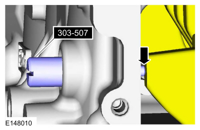
NOTICE:
Only rotate the crankshaft clockwise.
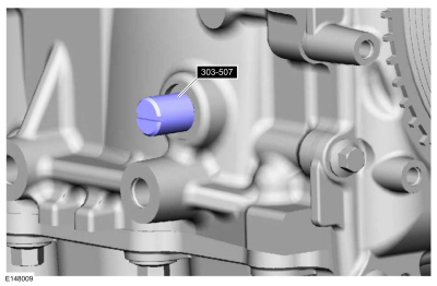
-
Install Special Service Tool: 303-507
Timing Peg, Crankshaft TDC.
-
Rotate the crankshaft slowly clockwise until the
crankshaft balance weight is up against the special tool. The engine is
now at TDC .
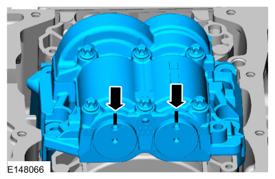
-
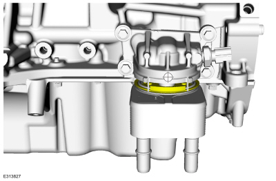
NOTE:
Due to the precision interior construction of the balancer unit, it should not be disassembled.
NOTE:
The original adjustment shims must be installed in their original positions.
NOTE:
Confirm by visual inspection that there is no damage to
the balancer unit gear and verify that the shaft turns smoothly. If
there is any damage or malfunction, replace the balancer unit.
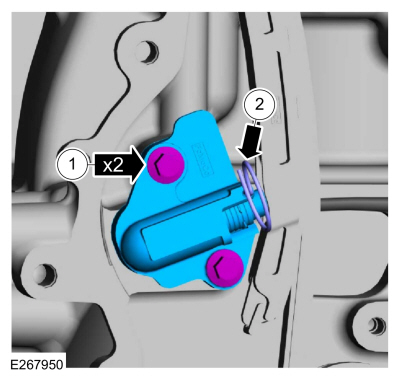
Install the adjustment shims in their original positions on
the seat faces of the balancer unit. With the balancer unit shaft marks
in the TDC position, slowly
install the balancer unit to the cylinder block to avoid interference
between the crankshaft drive gear and the balancer unit driven gear.
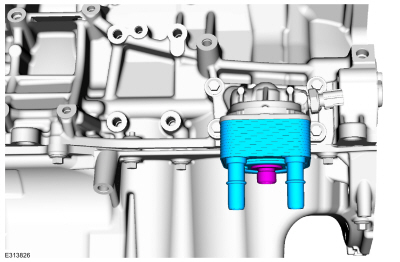
-
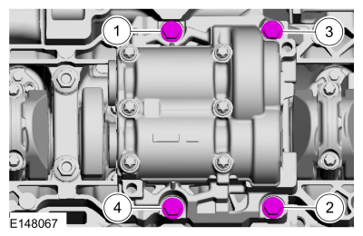
Install the bolts and tighten in sequence shown in 2 stages.
Torque:
Stage 1:
18 lb.ft (25 Nm)
Stage 2:
38 lb.ft (52 Nm)
-
NOTICE:
Only rotate the crankshaft clockwise.
-
Remove Special Service Tool: 303-507
Timing Peg, Crankshaft TDC.
-
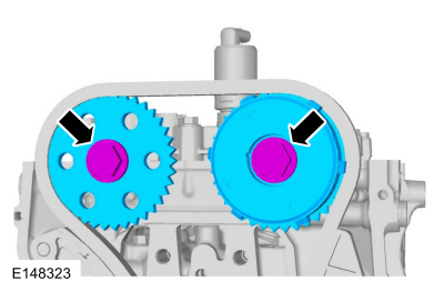
Rotate the crankshaft to confirm that there are no
meshing problems between the balancer unit gear and the crankshaft gear.
-
NOTICE:
Only rotate the crankshaft clockwise.
-
Install Special Service Tool: 303-507
Timing Peg, Crankshaft TDC.
-
Rotate the crankshaft slowly clockwise until the crankshaft balance weight is up against the special tool.
-
Remove Special Service Tool: 303-507
Timing Peg, Crankshaft TDC.
 |
|
-
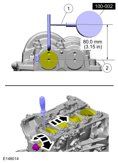
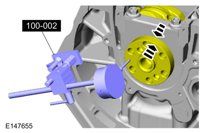
NOTE:
Measure the backlash and verify that it is within
specified range at all of the following 6 positions: 10 degrees, 30
degrees, 100 degrees, 190 degrees, 210 degrees and 280 degrees. It will
be necessary to reset the measuring equipment between measurements.
NOTE:
The measurement must be taken with the Dial Indicator
Gauge with Holding Fixture, a 5-mm Allen wrench and worm clamp set up as
shown. Mark the Allen wrench with a file 80 mm (3.149 in) above the
driven gear shaft center. Make sure the worm clamp and Allen wrench are
not touching the balance shaft housing.
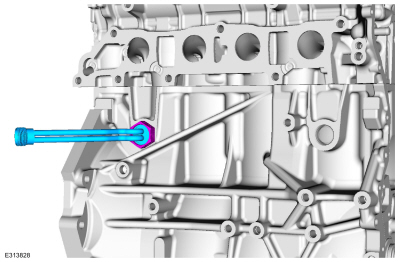
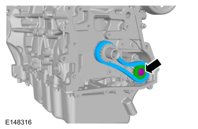
NOTE:
For an accurate measurement while measuring the gear
backlash, insert a screwdriver as shown into the crankshaft No. 1
crankweight area and set both the rotation and the thrust direction with
the screwdriver, using a prying action as shown.
-
Position as shown. Measure the gear backlash.
Use Special Service Tool: 100-002
(TOOL-4201-C)
Holding Fixture with Dial Indicator Gauge.
-
Position the Dial Indicator Gauge with Holding Fixture
(1) on the Allen wrench 80 mm (3.149 in) above the driven gear shaft
center (2) on the balancer unit.
-
Rotate the crankshaft clockwise and measure the backlash
at all of the following 6 positions: 10 degrees, 30 degrees, 100
degrees, 190 degrees, 210 degrees and 280 degrees.
-
Backlash specifications are 0.005 to 0.101 mm (0.00019 to 0.0039 in).
-
If the backlash exceeds the specified range, carry out the balance shaft backlash procedure.
Refer to: Balance Shaft Backlash (303-01C Engine, General Procedures).
 |
|
-
NOTICE:
Only rotate the crankshaft clockwise.
-
Install Special Service Tool: 303-507
Timing Peg, Crankshaft TDC.
-
Rotate the crankshaft slowly clockwise until the
crankshaft balance weight is up against the special tool. The engine is
now at TDC and must remain at the TDC position until the timing drive components and crankshaft pulley are installed.
-
Prime the oil pump. Add 2 tablespoons of clean engine oil to the oil pump and rotate the oil pump by hand.
Refer to: Specifications (303-01C Engine, Specifications).
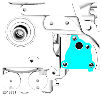
-
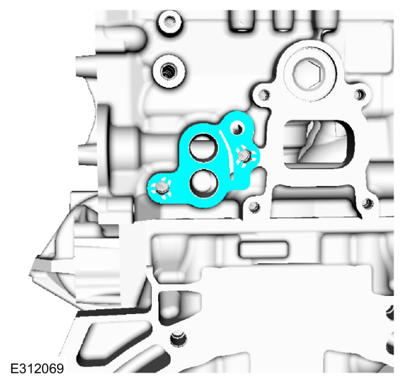
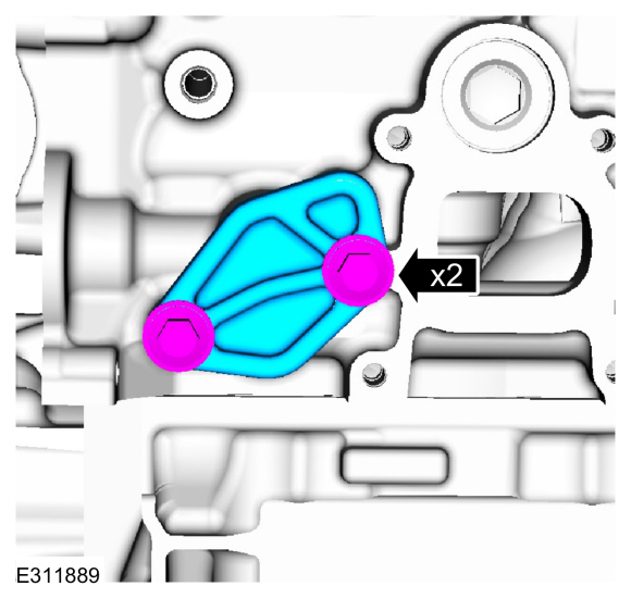
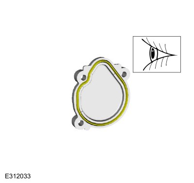
Install the new oil pump gasket.
-
NOTE:
Clean the oil pump and cylinder block mating surfaces with metal surface prep.
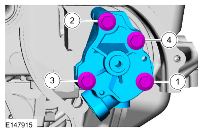
Install the oil pump and the bolts. Tighten in sequence shown in 2 stages.
Material: Motorcraft® Metal Surface Prep Wipes
/ ZC-31-B
Torque:
Stage 1:
89 lb.in (10 Nm)
Stage 2:
177 lb.in (20 Nm)
-
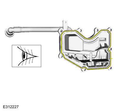
Lubricate new gasket with clean engine oil and install.
-
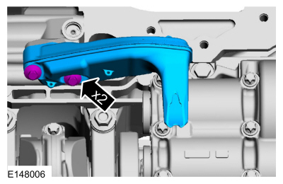
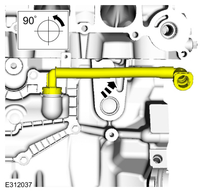
Install the oil pickup tube and the bolts.
Torque:
89 lb.in (10 Nm)
-
-
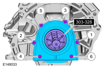
Using the special tool, position the crankshaft rear oil seal onto the crankshaft.
Use Special Service Tool: 303-328
(T88P-6701-B1)
Replacer, Rear Seal.
-
Install the bolts and tighten in sequence shown.
Torque:
89 lb.in (10 Nm)
-
NOTE:
If the oil pan is not secured within 10 minutes of
sealant application, the sealant must be removed and the sealing area
cleaned with metal surface prep. Allow to dry until there is no sign of
wetness, or 10 minutes, whichever is longer. Failure to follow this
procedure can cause future oil leakage.
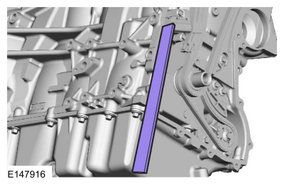
Apply a 3 mm bead of silicone sealant.
Material: Motorcraft® High Performance Engine RTV Silicone
/ TA-357
(WSE-M4G323-A6)
-
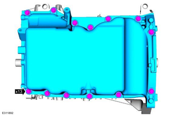
NOTE:
Only tighten the bolts finger tight at this stage.
Install the oil pan and the bolts finger tight.
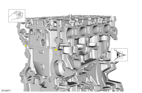
-
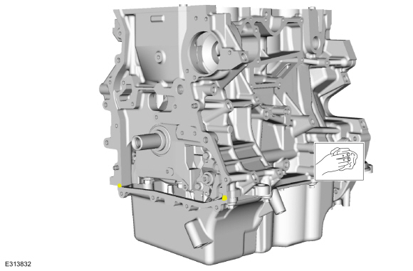
Using a straight edge, align the front surface of the oil pan flush with the front surface of the engine block.
Use the General Equipment: Round-Ended Steel Rule
-
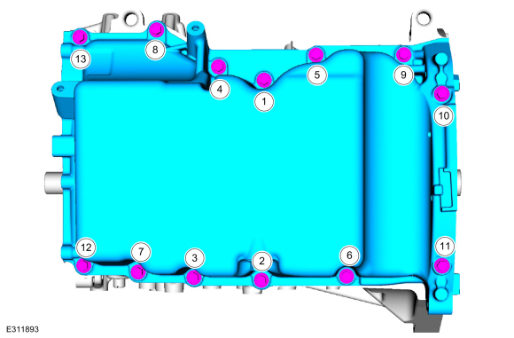
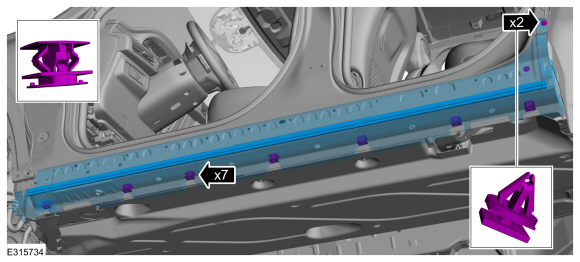
Tighten the bolts in sequence shown.
Torque:
Fasteners 1-9:
Stage 1:
177 lb.in (20 Nm)
Stage 2:
45°
Fasteners 10-11:
Stage 3:
177 lb.in (20 Nm)
Stage 4:
90°
Fasteners 12-13:
Stage 5:
177 lb.in (20 Nm)
Stage 6:
45°
-
Remove any excess sealer from the intersection of the cylinder block and oil pan.
-
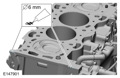
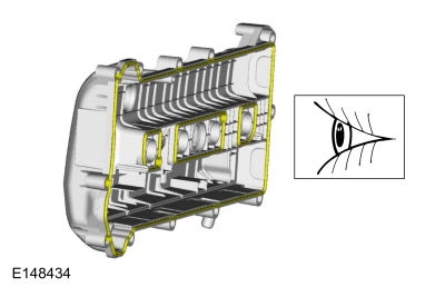
NOTE:
Dowels must be fully seated in the cylinder block.
Install the cylinder head alignment dowels.
-
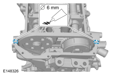
Apply a 6 mm bead of silicone sealant.
Material: Motorcraft® High Performance Engine RTV Silicone
/ TA-357
(WSE-M4G323-A6)
-
Install a new cylinder head gasket.
-
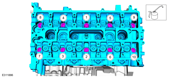
NOTE:
The cylinder head bolts are torque-to-yield and must not be reused. New cylinder head bolts must be installed.
NOTE:
Lubricate the bolts with clean engine oil prior to installation.
Install the cylinder head and the new bolts. Tighten in sequence shown in 5 stages.
Torque:
Stage 1:
62 lb.in (7 Nm)
Stage 2:
133 lb.in (15 Nm)
Stage 3:
33 lb.ft (45 Nm)
Stage 4:
90°
Stage 5:
90°
-
Remove excess sealer from the intersection of the cylinder block and cylinder head.
-
Install a new blanking plate gasket.
-
Install the blanking plate and bolts.
Torque:
177 lb.in (20 Nm)
-
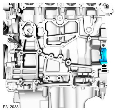
If equipped.
-
Install the block heater.
Torque:
41 lb.ft (55 Nm)
-
Install the new studs.
Torque:
150 lb.in (17 Nm)
-
NOTE:
Coat the valve tappets with clean engine oil prior to installation.
Install the valve tappets.
-
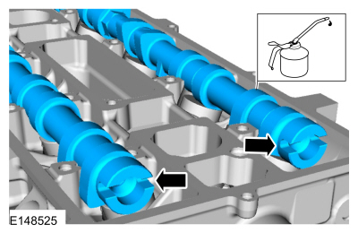
NOTE:
Install the camshafts with the alignment slots in the
camshafts lined up so the Camshaft Alignment Plate can be installed
without rotating the camshafts. Make sure the lobes on the No. 1
cylinder are in the same position as noted in the disassembly procedure.
Rotating the camshafts when the timing chain is removed, or installing
the camshafts 180 degrees out of position, can cause severe damage to
the valves and pistons.
Lubricate the camshafts with clean engine oil and position in the cylinder head.
-
-
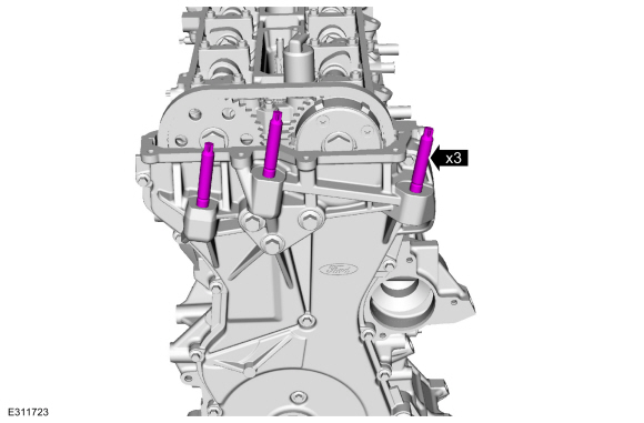
Lubricate the camshaft bearing caps with clean engine oil and install the camshaft bearing caps and bolts.
-
Tighten the camshaft bearing cap bolts one turn at a time, until finger-tight.
-
Tighten the bolts in sequence shown in 2 stages.
Torque:
Stage 1:
62 lb.in (7 Nm)
Stage 2:
142 lb.in (16 Nm)
-
Install the VCT oil control solenoid and the bolt.
Torque:
97 lb.in (11 Nm)
-
Install the oil pump drive gear, chain and the bolt.
Torque:
18 lb.ft (25 Nm)
-
-
Install the timing chain tensioner and the shoulder bolts.
Torque:
89 lb.in (10 Nm)
-
Push the tensioner spring down and position the spring under the shoulder bolt.
-
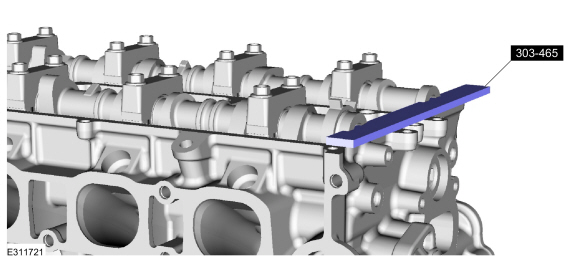
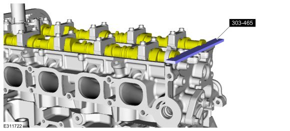
NOTE:
The Camshaft Alignment Plate is for camshaft alignment
only. Using this tool to prevent engine rotation can result in engine
damage.
Install Special Service Tool: 303-465
Tool, Camshaft Align Timing.
-
NOTE:
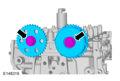
Only tighten the bolts finger tight at this stage.
Install the camshaft sprocket and the bolts.
-
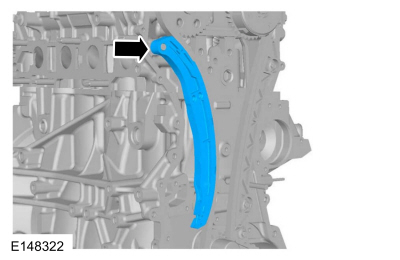
Install the timing chain guide and the bolts.
Torque:
89 lb.in (10 Nm)
-
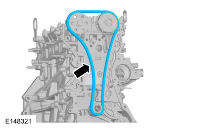
Install the timing chain.
-
Install the timing chain tensioner arm.
NOTE:
If the timing chain tensioner plunger is not pinned in the compressed position, follow the next step.
-
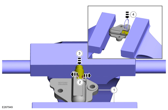
Reset the timing chain tensioner.
-
Position the timing chain tensioner in a soft-jawed vise.
-
Spread the ends of the ratchet wire clip apart.
-
Using the soft-jawed vise, compress the plunger to the reset position.
-
Install a locking pin in the 2 holes of the timing chain tensioner body to hold the plunger in place.
-
NOTE:
Do not remove the locking pin until the tensioner bolts are tightened.
-
Install the timing chain tensioner and the bolts.
Torque:
89 lb.in (10 Nm)
-
Remove the locking pin.
-
NOTE:
The Camshaft Alignment Plate is for camshaft alignment
only. Using this tool to prevent engine rotation can result in engine
damage.
NOTE:
Use the flats on the camshafts to prevent camshaft rotation.
Tighten the camshaft sprocket bolts in 2 stages.
Torque:
Stage 1:
30 lb.ft (40 Nm)
Stage 2:
60°
-
NOTE:
The engine front cover must be secured within 10 minutes
of Silicone Gasket and Sealant application. If the engine front cover
is not secured within 10 minutes, the sealant must be removed and the
sealing area cleaned with Motorcraft® Metal Surface Prep.
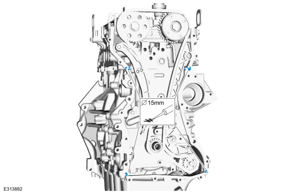
Apply a 15 mm (0.59 in) drop of silicone sealant at the
cylinder head-to-cylinder block and cylinder block-to-oil pan joint
areas.
Material: Motorcraft® High Performance Engine RTV Silicone
/ TA-357
(WSE-M4G323-A6)
-
NOTE:
The engine front cover must be secured within 10 minutes
of Silicone Gasket and Sealant application. If the engine front cover
is not secured within 10 minutes, the sealant must be removed and the
sealing area cleaned with Motorcraft® Metal Surface Prep.
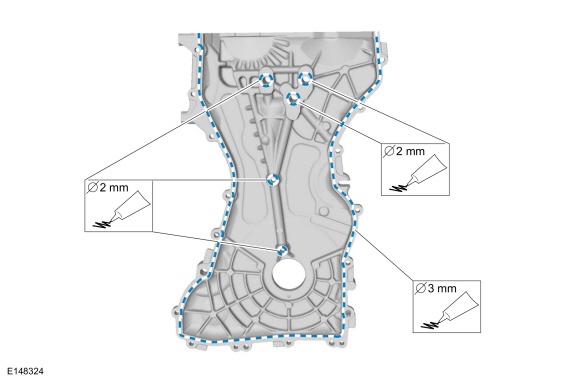
Apply a 3 mm bead of silicone sealant to the outside sealing
surfaces of the engine front cover. Apply a 2 mm bead of silicone
sealant to the inside sealing surfaces.
Material: Motorcraft® High Performance Engine RTV Silicone
/ TA-357
(WSE-M4G323-A6)
-
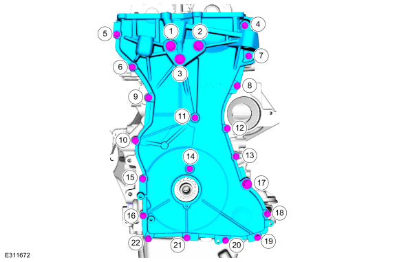
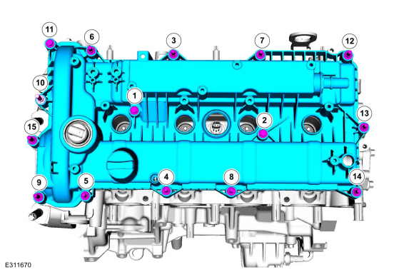
Install the engine front cover and the bolts. Tighten in sequence shown.
Torque:
Stage 1:
Bolts 1 - 3:
35 lb.ft (48
Nm)
Stage 2:
Bolts 4 - 16:
89 lb.in (10
Nm)
Stage 3:
Bolt 17:
35 lb.ft (48 Nm)
Stage 4:
Bolts 18 - 22:
89 lb.in (10
Nm)
-
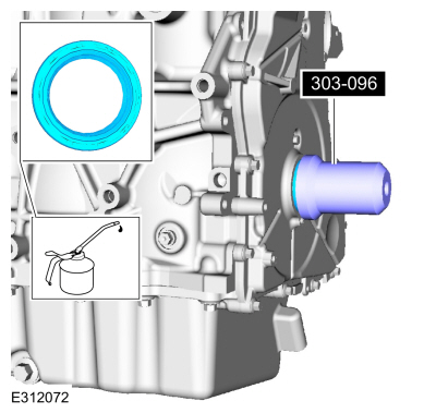
NOTE:
Remove the through-bolt from the Camshaft Front Oil Seal Installer.
Using the special tool, lubricate and install the crankshaft front seal.
Use Special Service Tool: 303-096
(T74P-6150-A)
Installer, Camshaft Front Oil Seal.
-
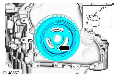
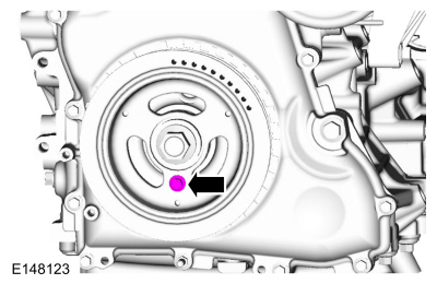
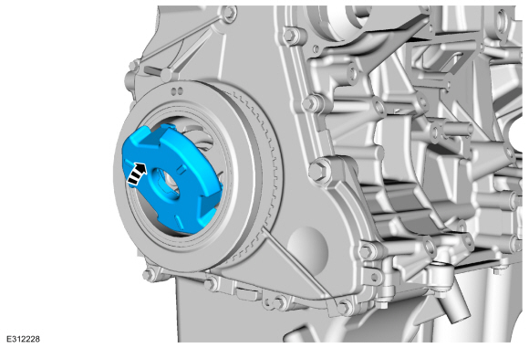
NOTE:
Apply clean engine oil on the seal before installing.
NOTE:
Do not install the crankshaft pulley bolt at this time.
Position the crankshaft pulley onto the crankshaft with the in the pulley at the 6 o'clock position.
-
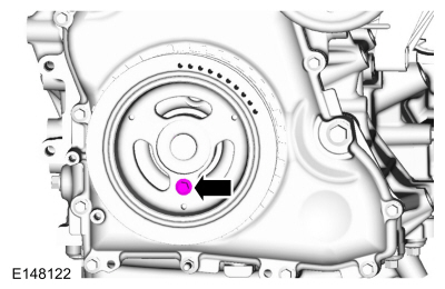
NOTE:
Only hand-tighten the 6 mm x 18 mm bolt or damage to the front cover can occur.
NOTE:
This step will correctly align the crankshaft pulley to the crankshaft.
Install a standard M6 X 18 mm bolt through the crankshaft pulley and thread it into the engine front cover.
-
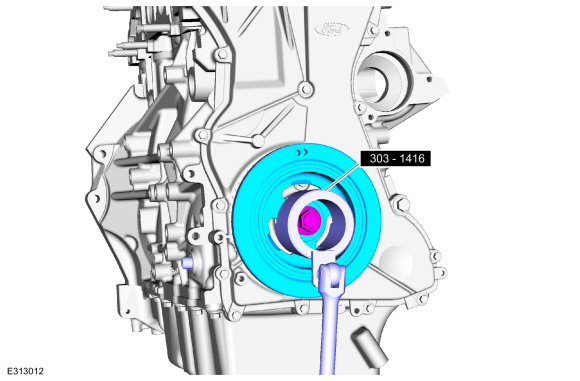
NOTE:
The crankshaft must remain in the TDC
position during installation of the pulley bolt or damage to the
engine can occur. Therefore, the crankshaft pulley must be held in place
with the Crankshaft Damper Holding Tool and the bolt should be
installed using hand tools only.
NOTE:
Install a new crankshaft pulley bolt.
Using the special tool, tighten the new crankshaft pulley bolt in 2 stages.
Use Special Service Tool: 303-1416
Tool, Crank Damper Holding.
Torque:
Stage 1:
74 lb.ft (100 Nm)
Stage 2:
90°
-
Remove the standard M6 X 18 mm bolt.
-
Remove Special Service Tool: 303-507
Timing Peg, Crankshaft TDC.
-
Remove Special Service Tool: 303-465
Tool, Camshaft Align Timing.
-
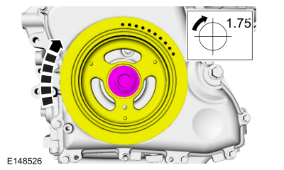
NOTE:
Only turn the engine in the normal direction of rotation.
Rotate the crankshaft clockwise one and three-fourth turns.
-
NOTICE:
Only rotate the crankshaft clockwise.
-
Install Special Service Tool: 303-507
Timing Peg, Crankshaft TDC.
-
Turn the crankshaft clockwise until the crankshaft contacts the special tool.
-
NOTE:
Only hand-tighten the bolt or damage to the front cover can occur.
Install a standard M6 X 18 mm bolt. Check the position of
the crankshaft pulley. If it is not possible to install the bolt, the
engine valve timing must be corrected.
-
If it is not possible to install the Camshaft Alignment Plate, the engine valve timing must be corrected.
Install Special Service Tool: 303-465
Tool, Camshaft Align Timing.
-
Remove Special Service Tool: 303-465
Tool, Camshaft Align Timing.
-
NOTE:
Only tighten the bolts finger tight at this stage.
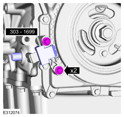
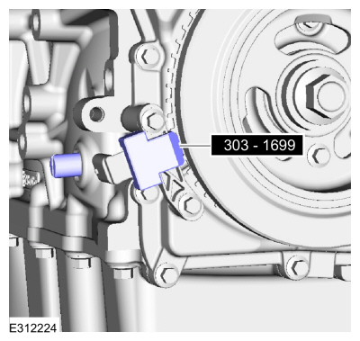
Install the CKP sensor and the bolts.
-
If the special service tool mark does not align with the TDC marked
tooth on the crankshaft pulley, loosen the CKP sensor bolts and adjust
the sensor until the tool is installed then tighten.
Use Suggested Tool: 303-1699
Tool, Crank Sensor Alignment. Tool shown or a commercially available equivalent can be used.
Torque:
62 lb.in (7 Nm)
-
Remove Suggested Tool: 303-1699
Tool, Crank Sensor Alignment.
-
Remove the standard M6 X 18 mm bolt.
-
Remove Special Service Tool: 303-507
Timing Peg, Crankshaft TDC.
-
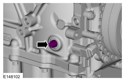
Install the engine plug bolt.
Torque:
177 lb.in (20 Nm)
-
Install the crankshaft pulley cover.
-
Install the engine mount studs.
Torque:
106 lb.in (12 Nm)
-
NOTE:
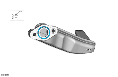
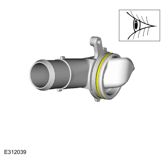
Lubricate with clean coolant.
Inspect the coolant outlet assembly o-ring and replace if necessary.
-
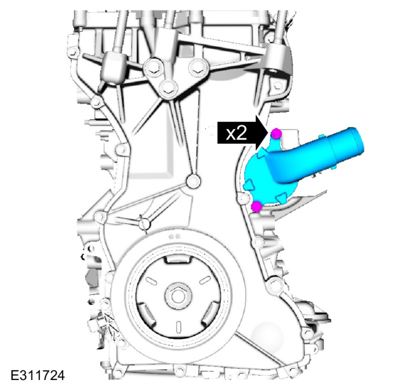
Install the coolant outlet assembly and bolts.
Torque:
89 lb.in (10 Nm)
-
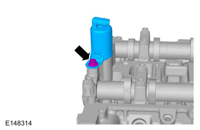
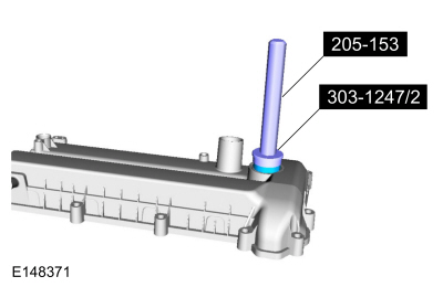
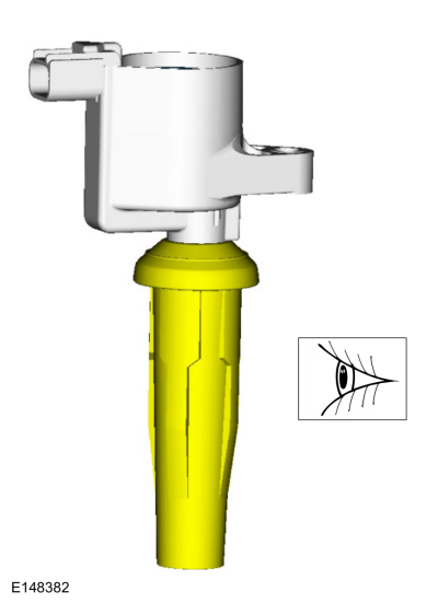
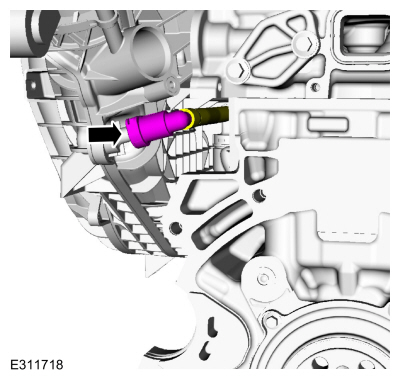
NOTE:
Installation of a new VCT solenoid seal is required if a damaged seal was removed during disassembly of the engine.
Using the special tools, install the VCT oil control solenoid seal.
Use Special Service Tool: 303-1247
VCT Spark Plug Tube Seal Remover and Installer.
, 205-153
(T80T-4000-W)
Handle.
-
Inspect and if necessary, install new valve cover gaskets.
-
Apply a 6 mm bead of silicone sealant.
Material: Motorcraft® High Performance Engine RTV Silicone
/ TA-357
(WSE-M4G323-A6)
-
NOTE:
The valve cover must be secured within 10 minutes of
silicone gasket application. If the valve cover is not secured within 10
minutes, the sealant must be completely removed and the sealing area
cleaned with metal surface cleaner.
Install the valve cover and tighten the fasteners in sequence shown.
Torque:
89 lb.in (10 Nm)
-
Inspect the ignition coil-on-plug boots for cracks, rips, or tears. Replace any damaged coil-on-plug boots.
-
NOTE:
Apply dielectric compound to the inside of the coil-on-plug boots.
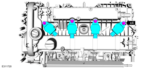
Install the ignition coil-on-plugs and the bolts.
Material: Motorcraft® Silicone Brake Caliper Grease and Dielectric Compound
/ XG-3-A
(ESA-M1C200-A)
(ESE-M1C171-A)
Torque:
71 lb.in (8 Nm)
-
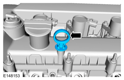
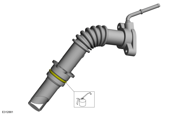
Install the oil level indicator.
-
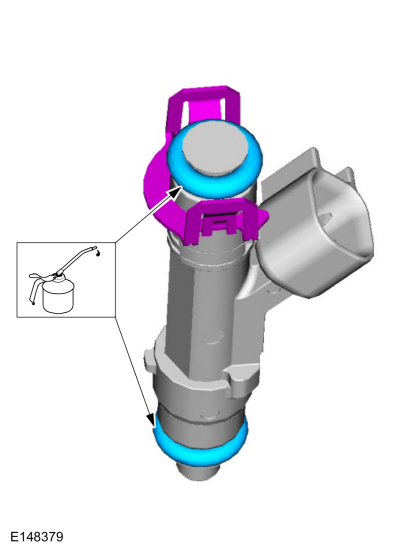
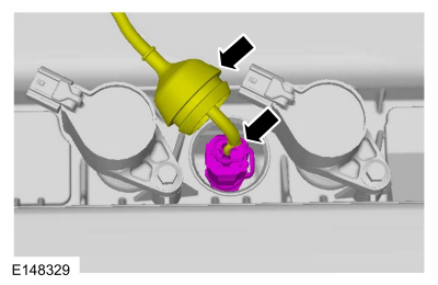
NOTE:
Use O-ring seals that are made of special fuel-resistant
material. Use of ordinary O-rings can cause the fuel system to leak. Do
not reuse the O-ring seals.
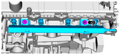
Install the fuel injector retaining clips and the fuel
injector O-ring seals. Lubricate the fuel injector O-ring seals.
-
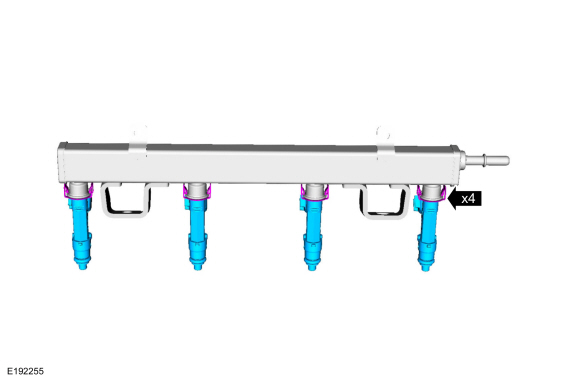
Install the fuel injectors into the fuel rail.
-
Install the fuel rail assembly and the studs.
Torque:
Stage 1:
18 lb.ft (25 Nm)
Stage 2:
30°
-
Install the radio capacitor and nut.
-
NOTE:
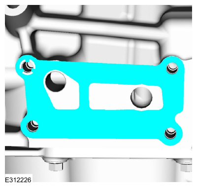
Clean the gasket mating surface with metal surface prep.
Install a new gasket.
Material: Motorcraft® Metal Surface Prep Wipes
/ ZC-31-B
-
Install the oil filter adapter and the bolts.
Torque:
18 lb.ft (25 Nm)
-
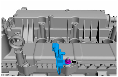
Install the oil pressure sender.
Torque:
97 lb.in (11 Nm)
-
If equipped.
Position the oil cooler alignment tab between the anti-rotation feature on the oil filter adapter.
-
If equipped.
Install the oil cooler.
Torque:
41 lb.ft (55 Nm)
-
Install the converter cover.
-
Inspect the water inlet cover gasket and replace if necessary.
-
Install the water inlet cover and bolts.
Torque:
89 lb.in (10 Nm)
-
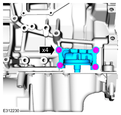
Inspect the crankcase vent oil separator gasket and replace if necessary.
-
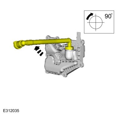
Rotate the PCV tube prior to installation.
-
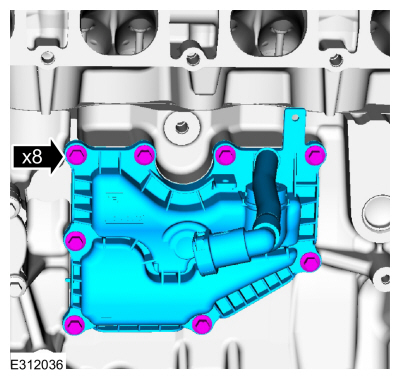
Install the crankcase vent oil separator and the bolts.
Torque:
89 lb.in (10 Nm)
-
Rotate the PCV tube back to initial position.
-
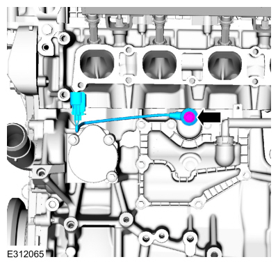
Install the KS and the bolt.
Torque:
177 lb.in (20 Nm)
-
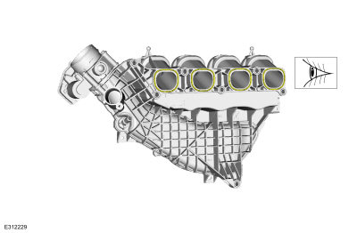
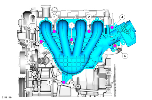
Inspect the intake manifold gaskets and replace if necessary.
-
Position the intake manifold and connect the crankcase vent oil separator tube.
-
Position back the intake manifold and install the bolts. Tighten the bolts in sequence shown.
Torque:
159 lb.in (18 Nm)
-
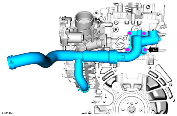
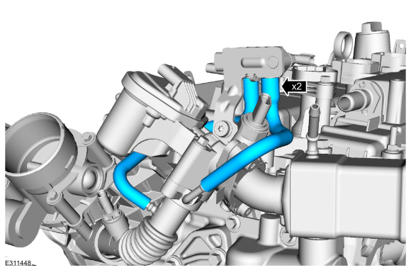
Install the water outlet housing, bolts and hoses. Tighten the bolts finger tight.
-
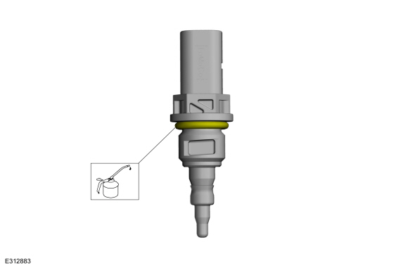
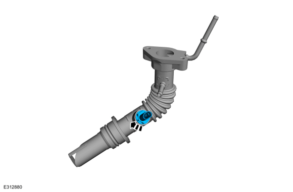
Lubricate the o-ring seal with clean engine oil. Replace the o-ring if necessary.
-
Lubricate the o-ring seal with clean engine oil. Replace the o-ring if necessary.
-
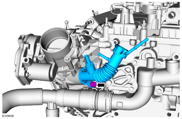
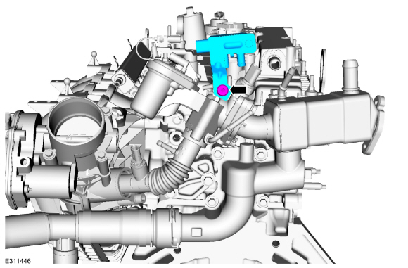
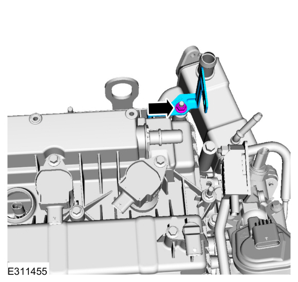
Install the EGR cooler outlet temperature sensor.
-
Install the EGR outlet tube and fastener.
-
-
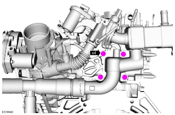
Install the EGR valve and fasteners, then tighten in the sequence shown.
Torque:
89 lb.in (10 Nm)
-
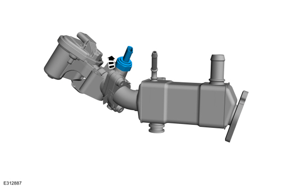
Install the EGR back pressure sensor.
Torque:
97 lb.in (11 Nm)
-
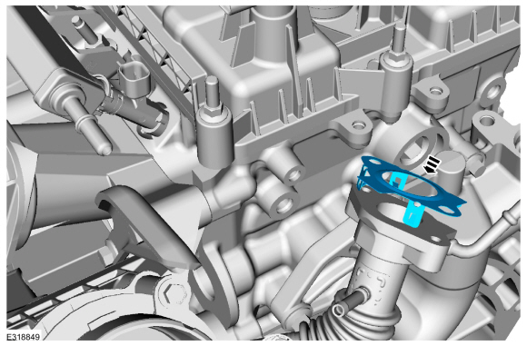
Install the EGR outlet tube gasket.
-
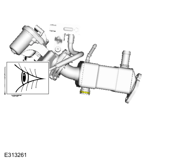
Inspect the EGR cooler o-ring seal replace if necessary.
-
Lubricate the new EGR cooler O-ring with a small amount of engine oil.
-
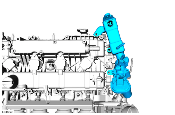
Install the EGR valve and EGR cooler assembly.
-
Install the EGR assembly bolt and hand tighten the bolt at this stage.
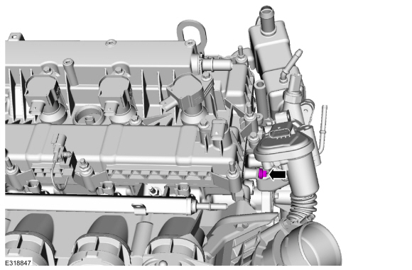
-
Install the EGR assembly mounting bolt.
Torque:
89 lb.in (10 Nm)
-
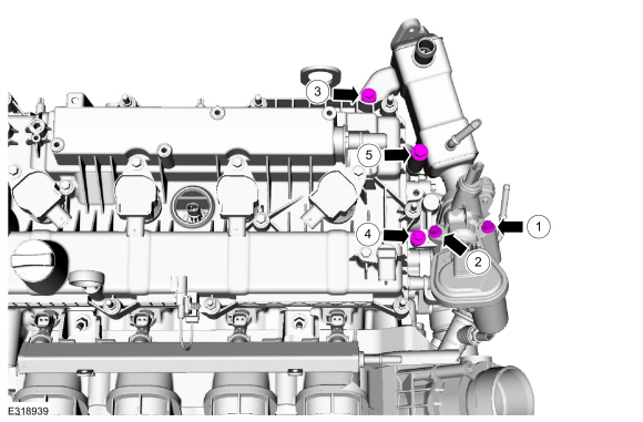
Install the EGR assembly bolts and hand tighten the bolts at this stage.
-
Tighten in the sequence shown.
Torque:
1:
89 lb.in (10 Nm)
2:
89 lb.in (10 Nm)
3:
89 lb.in (10 Nm)
4:
89 lb.in (10 Nm)
5:
18 lb.ft (25 Nm)
-
Tighten in the sequence shown.
Torque:
Stage 1:
89 lb.in (10 Nm)
Stage 2:
45°
-
Install the differential pressure feedback EGR sensor assembly and the fastener.
Torque:
89 lb.in (10 Nm)
-
Connect the differential pressure sensor hoses.
-
Install the fuel line bracket and nut.
-
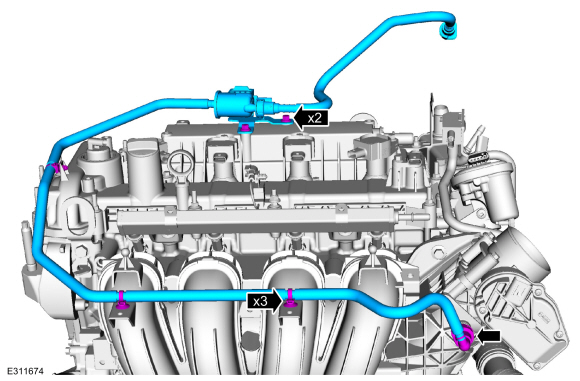
Remove the bolts, pin-type retainers, and the fuel vapor tube.
Refer to: Quick Release Coupling (310-00C Fuel System - General Information, General Procedures).
Torque:
27 lb.in (3 Nm)
-
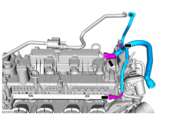
Install the crankcase vent tube, fuel line and pin-type retainer.
Refer to: Quick Release Coupling (310-00C Fuel System - General Information, General Procedures).
Refer to: Spring Lock Couplings (310-00C Fuel System - General Information, General Procedures).
-
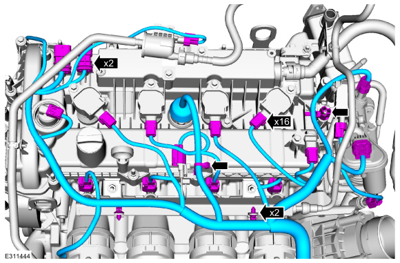
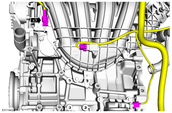
Install the wire harness, connect the electrical connectors and attach the retainers.
-
Connect the CHT sensor electrical connector and position back the boot.
-
Connect the electrical connectors.
-
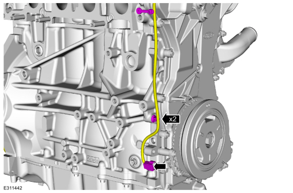
Connect the CKP electrical connector and attach the pin-type retainers.
-
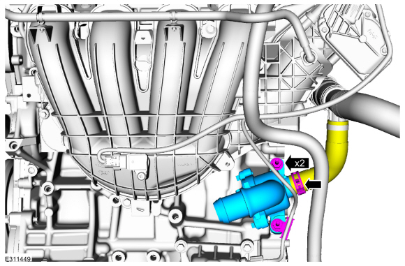
Position back the thermostat housing, install the studs and coolant hose.
Use the General Equipment: Hose Clamp Remover/Installer
Torque:
35 lb.ft (47 Nm)
-
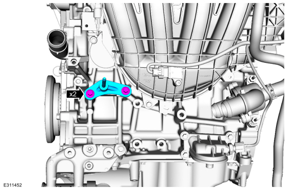
Install the bracket and fasteners.
Torque:
18 lb.ft (25 Nm)
-
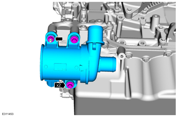
Install the coolant pump and fasteners.
Torque:
18 lb.ft (25 Nm)
-
Install the A/C bracket and bolts.
Torque:
18 lb.ft (25 Nm)
-
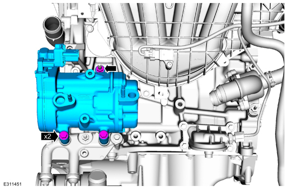
Install the A/C compressor and fasteners.
Torque:
18 lb.ft (25 Nm)
-
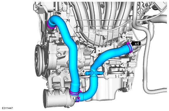
Install the coolant hoses.
Use the General Equipment: Hose Clamp Remover/Installer
-
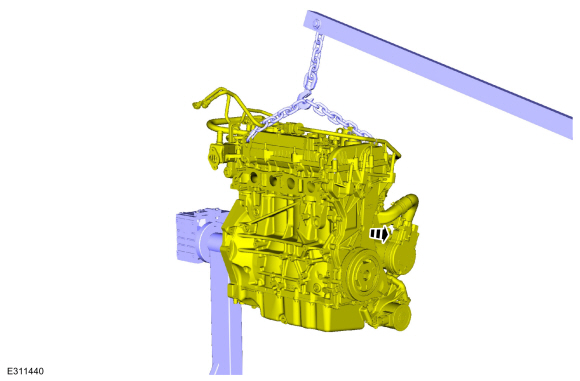
Install the engine lift equipment.
-
Remove the engine from the mounting stand.
Use the General Equipment: Mounting Stand
-
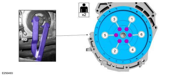
NOTE:
Use a universal pulley holder.
-
Use a universal pulley holder (such as an OTC 4754, or
equivalent). Install the flywheel and the new bolts. Using a universal
pulley holder, tighten the new crankshaft pulley bolts in sequence
shown.
Torque:
Stage 1:
37 lb.ft (50 Nm)
Stage 2:
59 lb.ft (80 Nm)
Stage 3:
83 lb.ft (112 Nm)
-
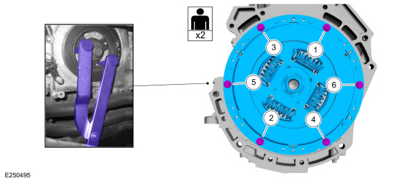
Remove the universal pulley holder.
-
Using a universal pulley holder, tighten 2 turns at a time in sequence shown.
Torque:
21 lb.ft (29 Nm)
Materials
Name
Specification
Engine Oil - SAE 5W-20 - Synthetic Blend Motor OilXO-5W20-Q1SP
WSS-M2C945-B1
DISASSEMBLY
Remove and discard the piston rings...
Special Tool(s) /
General Equipment
303-476
(T94P-9472-A)
Socket, Exhaust Gas Oxygen SensorTKIT-1994-LM/MTKIT-1994-FTKIT-1994-FLM/FM
Floor Crane
Adjustable Mounting Arm
Hose Clamp Remover/Installer
Fluid Container
Powertrain Jack
Wooden Block
Materials
Name
Specification
Motorcraft® High Temperature Nickel Anti-Seize LubricantXL-2
-
..
Other information:
Exterior Bulbs
Exterior Bulb Specification Chart
1 To replace these lamps, see your
authorized dealer.
Changing a Headlamp Bulb
WARNING: Make sure the bulbs
have cooled down before removing
them. Failure to follow this warning could
result in serious personal injury.
Note: Handle a halogen headlamp bulb
carefully and keep out of children’s reach.
Grasp the bulb by only its plastic base an..
Overview
The transmission fluid cooling system consists of the following:
Transmission fluid cooler tubes
Transmission fluid cooler
This
vehicle is equipped with an external air cooled transmission fluid
cooler. Transmission fluid flows from the transmission through the
transmission fluid cooler via the transmission fluid cooler tubes.
Component Location
Item..
.jpg)
.jpg)
.jpg)
.jpg)
.jpg)
.jpg)
.jpg)
.jpg)
.jpg)
.jpg)
.jpg)
.jpg)
.jpg)
.jpg)
.jpg)
 Disassembly and Assembly of Subassemblies - Piston
 Installation - Engine