Ford Escape: Engine / Installation - Engine
Special Tool(s) /
General Equipment
 |
303-476
(T94P-9472-A)
Socket, Exhaust Gas Oxygen Sensor
TKIT-1994-LM/M
TKIT-1994-F
TKIT-1994-FLM/FM |
| Floor Crane |
| Adjustable Mounting Arm |
| Hose Clamp Remover/Installer |
| Fluid Container |
| Powertrain Jack |
| Wooden Block |
Materials
| Name |
Specification |
Motorcraft® High Temperature Nickel Anti-Seize Lubricant
XL-2 |
-
|
-
Inspect the engine block dowels. If the dowels are damaged or missing, install new engine block dowels.
-
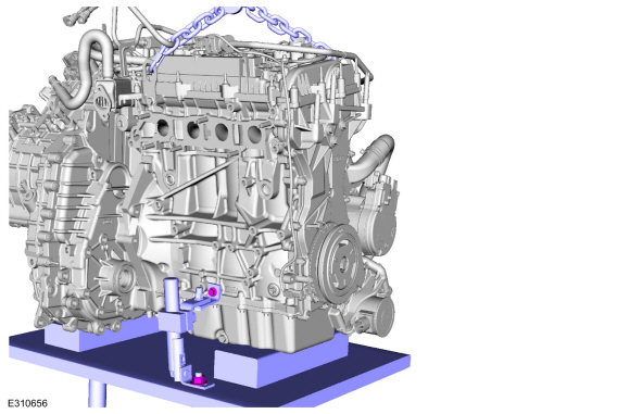
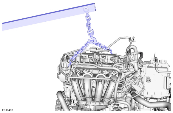
Install the engine to the transmission.
Use the General Equipment: Floor Crane
-
NOTE:
If the transmission is not positioned on the dowel pins, damage to the transmission may occur.
If the dowel pins were pulled out of the engine block during
removal, install new dowel pins in the engine block.
-
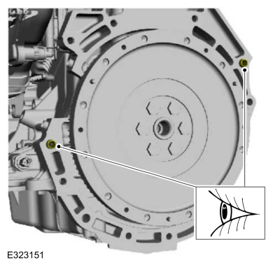
Install the RH engine to transmission bolts.
Torque:
35 lb.ft (48 Nm)
-
Install the LH engine to transmission bolts.
Torque:
35 lb.ft (48 Nm)
-
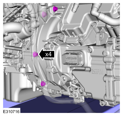
Install the RH adjustable mounting arm.
Use the General Equipment: Adjustable Mounting Arm
-
Install the LH adjustable mounting arm.
Use the General Equipment: Adjustable Mounting Arm
-
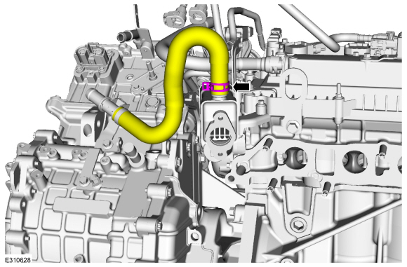
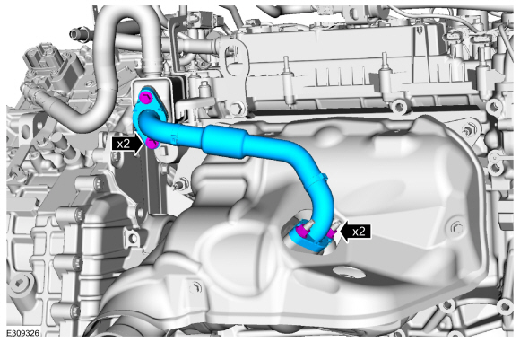
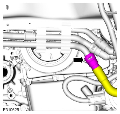
Install the EGR cooler hose.
-
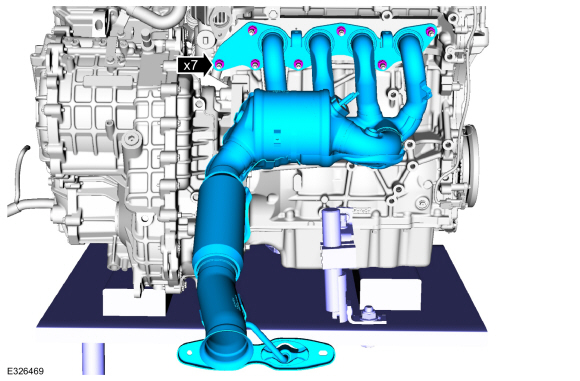
Install a new exhaust manifold gasket.
-
Install new nuts and the exhaust manifold.
Torque:
41 lb.ft (55 Nm)
-
Install the exhaust manifold heat shield and bolts.
Torque:
89 lb.in (10 Nm)
-
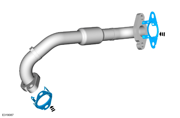
Clean and inspect the gasket surface and the studs. Replace the studs if necessary.
Torque:
159 lb.in (18 Nm)
-
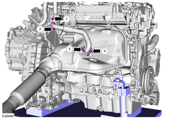
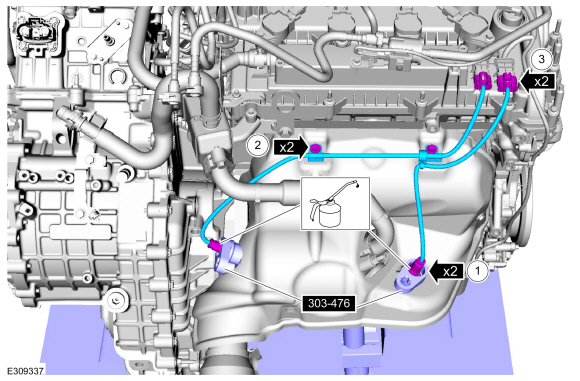
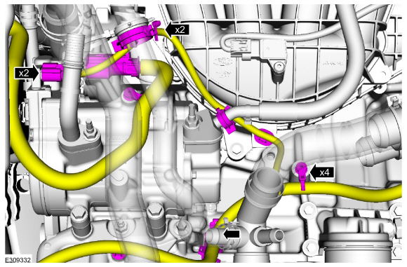
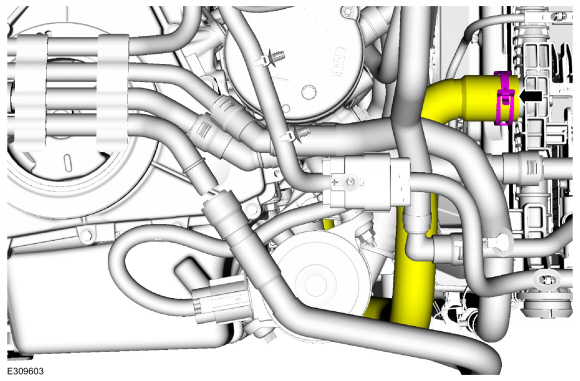
Install the new EGR cooler inlet tube gaskets.
-
NOTE:
Only tighten the nut and bolts finger tight at this stage.
-
Torque:
1:
89 lb.in (10 Nm)
2:
18 lb.ft (24 Nm)
1:
18 lb.ft (24 Nm)
3:
89 lb.in (10 Nm)
4:
18 lb.ft (24 Nm)
3:
18 lb.ft (24 Nm)
-
-
Calculate the correct torque wrench setting for the
following torque. Refer to Torque Wrench Adapter Formula in the Apex.
Install the HO2S .
Use Special Service Tool: 303-476
(T94P-9472-A)
Socket, Exhaust Gas Oxygen Sensor.
Material: Motorcraft® High Temperature Nickel Anti-Seize Lubricant
/ XL-2
Torque:
35 lb.ft (48 Nm)
-
Install the bolts and wire connector brackets.
-
Connect the HO2S electrical connector.
-
Remove the Floor Crane and commercially available quick link and chain.
Use the General Equipment: Floor Crane
-
Install the engine and transmission into the vehicle.
Use the General Equipment: Powertrain Jack
Use the General Equipment: Adjustable Mounting Arm
Use the General Equipment: Wooden Block
-
Install the transmission support insulator bolts finger tight.
-
NOTE:
Install all the nuts and bolts finger tight before final tightening.
-
Tighten the engine mount nuts.
Torque:
81 lb.ft (110 Nm)
-
Tighten the engine mount bolts.
Torque:
129 lb.ft (175 Nm)
-
Tighten the transmission support insulator bolts.
Torque:
92 lb.ft (125 Nm)
-
Remove the adjustable mounting arm.
Use the General Equipment: Powertrain Jack
Use the General Equipment: Adjustable Mounting Arm
Use the General Equipment: Wooden Block
-
Remove the adjustable mounting arm and the powertrain jack.
Use the General Equipment: Powertrain Jack
Use the General Equipment: Adjustable Mounting Arm
Use the General Equipment: Wooden Block
-
Install the front subframe.
Refer to: Front Subframe (502-00 Uni-Body, Subframe and Mounting System, Removal and Installation).
-
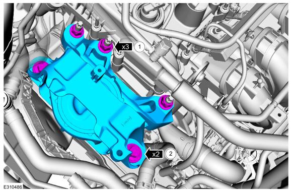
Install the roll restrictor bracket.
-
Install the stud and bolts.
Torque:
81 lb.ft (110 Nm)
-
Install the Clevis bolt.
Torque:
129 lb.ft (175 Nm)
-
Install the front halfshafts.
Refer to: Front Halfshaft LH (205-04 Front Drive Halfshafts, Removal and Installation).
Refer to: Front Halfshaft RH - 2.5L Duratec – Hybrid (121kW/164PS) (BG)
(205-04 Front Drive Halfshafts, Removal and Installation).
Refer to: Front Halfshaft RH (205-04 Front Drive Halfshafts, Removal and Installation).
-
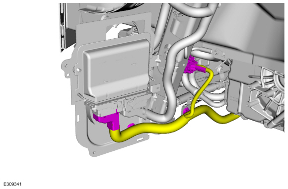
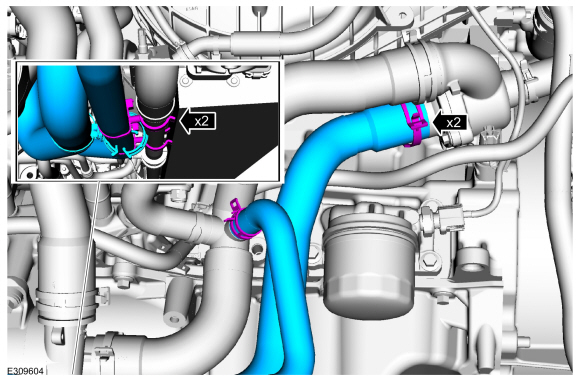
Install the coolant hoses.
Use the General Equipment: Hose Clamp Remover/Installer
-
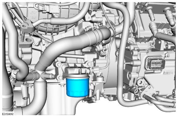
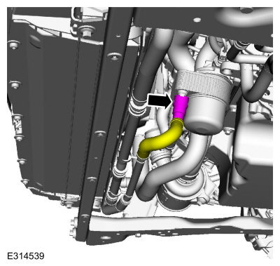
Install the engine oil filter.
Torque:
133 lb.in (15 Nm)
-
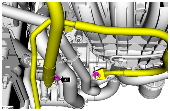
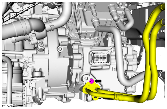
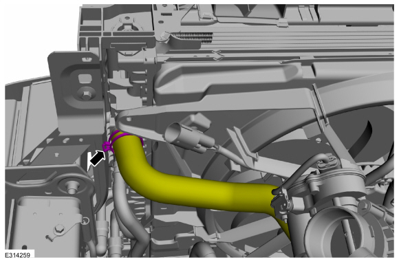
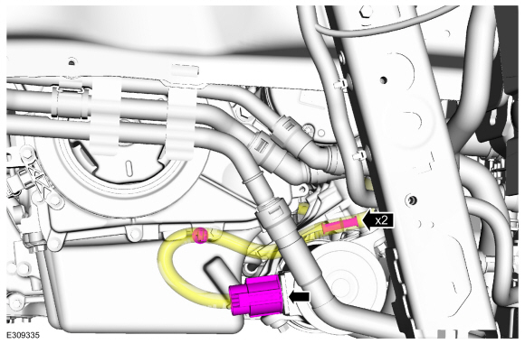
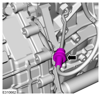
Install new O-ring and gasket seals and the A/C line and nuts.
Torque:
159 lb.in (18 Nm)
-
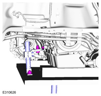
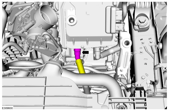
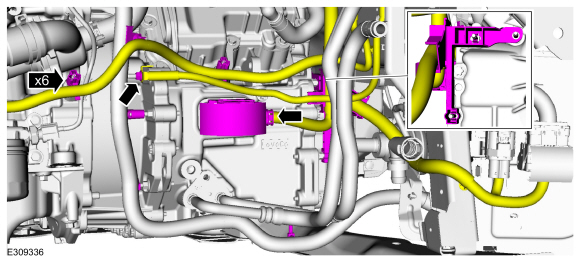
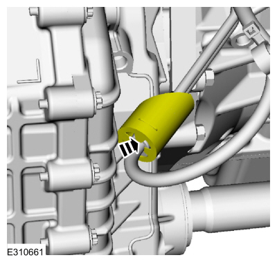
Install the transmission coolant line and bolt.
Use the General Equipment: Fluid Container
Torque:
18 lb.ft (25 Nm)
-
NOTE:
When connecting the coolant tube, push-click-pull on the coolant tubes to ensure proper connection.
Connect the coolant hose.
-
Connect the upper radiator hose.
Use the General Equipment: Hose Clamp Remover/Installer
-
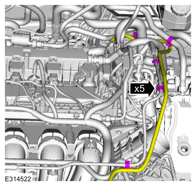
Connect the electrical connectors and install the wire harness retainers.
-
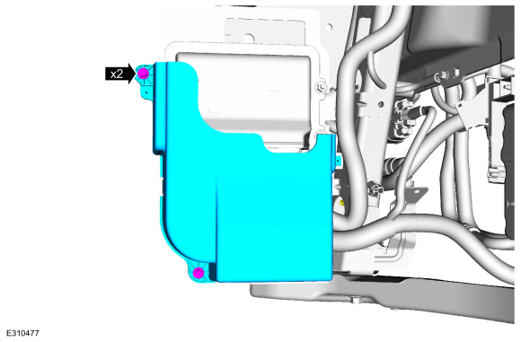
Install the PCM cover and bolts.
-
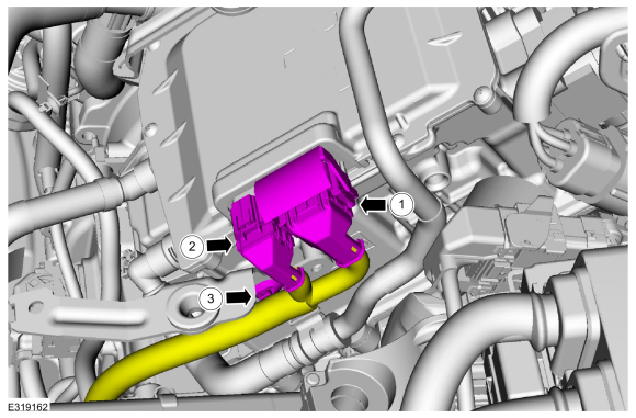
Connect the transmission electrical connector and install the wire harness retainers.
-
-
Position back the wire harness bracket and install the bolts.
-
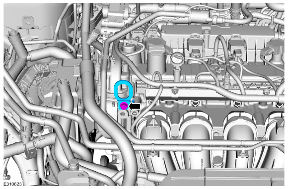
Connect the high voltage cable to the ISC and tighten the retainer.
Torque:
97 lb.in (11 Nm)
-
-
Connect C199A (40 pin connector) and engage the lever lock.
-
Connect C199B (22 pin connector).
-
Install the wire harness retainer.
-
Connect the A/C electrical connectors and install the wire harness retainers.
-
Connect the coolant pump electrical connector and install the wire harness retainers.
-
Install the coolant hoses and clips.
Use the General Equipment: Hose Clamp Remover/Installer
-
If equipped.
Connect the oil cooler hose.
Use the General Equipment: Hose Clamp Remover/Installer
-
If equipped with a block heater.
Connect the block heater electrical connector.
-
If equipped with a block heater.
Position back the block heater electrical connector cover.
-
Connect the coolant hose.
Use the General Equipment: Hose Clamp Remover/Installer
-
Connect the coolant hose.
Use the General Equipment: Hose Clamp Remover/Installer
-
If equipped with a block heater.
Connect the block heater electrical connector.
-
If equipped with a block heater.
Position back the block heater electrical connector cover.
-
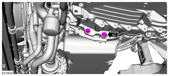
Install the oil pan bolts.
Torque:
35 lb.ft (48 Nm)
-
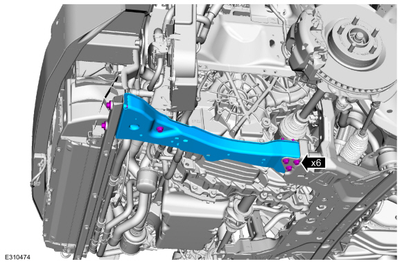
Install the LH subframe support bracket and new bolts.
Torque:
22 lb.ft (30 Nm)
-
Install the RH subframe support bracket and new bolts.
Torque:
22 lb.ft (30 Nm)
-
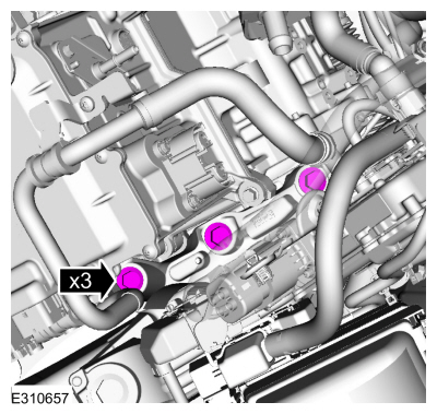
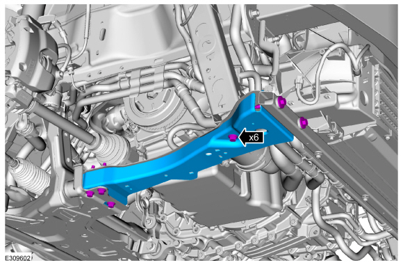
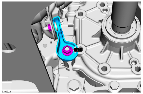
Install the exhaust manifold bracket and bolts.
Torque:
18 lb.ft (25 Nm)
-
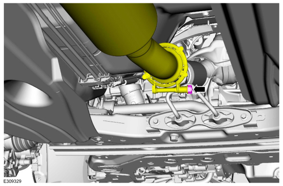
Install the new outlet clamp.
Torque:
17 lb.ft (23 Nm)
-
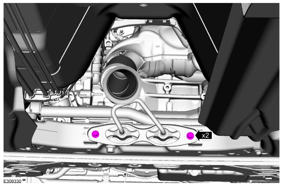
Install the bracket and nuts.
Torque:
35 lb.ft (48 Nm)
-
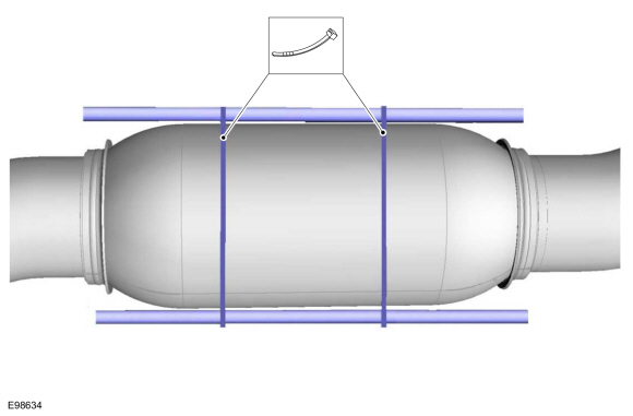
NOTICE:
Make sure that the component is not forcibly bent.
Remove the exhaust flexible pipe support.
-
NOTE:
When connecting the coolant tube, push-click-pull on the coolant tube to ensure proper connection.
Install the coolant hoses and the pin-type retainers.
Use the General Equipment: Hose Clamp Remover/Installer
-
If equipped.
Position back the block heater wire harness and attach the clips.
-
Remove the commercially available lift eye.
-
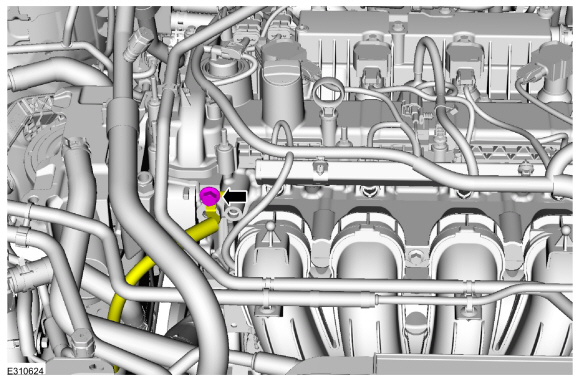
Install the ground wire.
Torque:
133 lb.in (15 Nm)
-
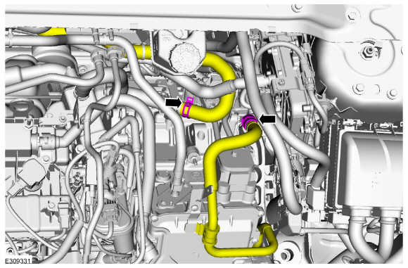
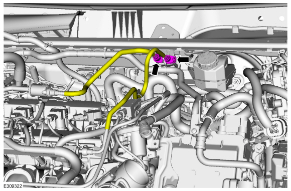
Connect the coolant hoses.
Use the General Equipment: Hose Clamp Remover/Installer
-
Connect the fuel vapor and fuel supply tubes.
Refer to: Quick Release Coupling (310-00C Fuel System - General Information, General Procedures).
Refer to: Spring Lock Couplings (310-00C Fuel System - General Information, General Procedures).
-
-
Install the air cleaner.
-
Connect the air cleaner inlet tube.
-
Tighten the clamp.
-
Connect the vent tube.
-
Install the bolt.
-
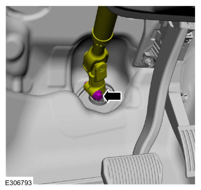
Position the steering column shaft back and install a new bolt.
Torque:
46 lb.ft (63 Nm)
-
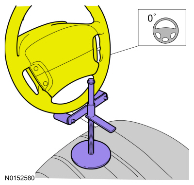
Using a holding device, hold the steering wheel in the straight-ahead position.
-
Install the following items:
-
Install the degas bottle.
Refer to: Degas Bottle (303-03C Engine Cooling, Removal and Installation).
-
Install the front bumper cover.
Refer to: Front Bumper Cover (501-19 Bumpers, Removal and Installation).
-
Install the fender front fender splash shields.
Refer to: Fender Splash Shield (501-02 Front End Body Panels, Removal and Installation).
-
Refer to: Specifications (303-01C Engine, Specifications).
-
Connect the battery connectors.
Refer to: Battery Cables - 2.5L Duratec – Hybrid (121kW/164PS) (BG)
(414-01 Battery, Mounting and Cables, Removal and Installation).
-
Repower the high-voltage system.
Refer to: High Voltage System De-energizing (414-03A High Voltage Battery, Mounting and Cables, General Procedures).
-
Pressurize the fuel system.
Refer to: Fuel System Pressure Release (310-00C Fuel System - General Information, General Procedures).
-
Fill and bleed the cooling system.
Refer to: Engine Cooling System Draining, Vacuum Filling and Bleeding (303-03C Engine Cooling, General Procedures).
-
Fill and bleed the Electric Powertrain Cooling System.
Refer to: Engine Cooling System Draining, Vacuum Filling and Bleeding (303-03C Engine Cooling, General Procedures).
-
Charge the A/C system.
Refer to: Air Conditioning (A/C) System Recovery, Evacuation and
Charging - 2.5L Duratec – Hybrid (121kW/164PS) (BG) (412-00 Climate
Control System - General Information, General Procedures).
Refer to: Air Conditioning (A/C) System Recovery, Evacuation and
Charging - 2.5L Duratec – Hybrid (121kW/164PS) (BG) (412-00 Climate
Control System - General Information, General Procedures).
-
Check and fill the transmission fluid as necessary.
Refer to: Transmission Fluid Level Check (307-01B Automatic Transmission - Automatic Transmission – HF45, General Procedures).
-
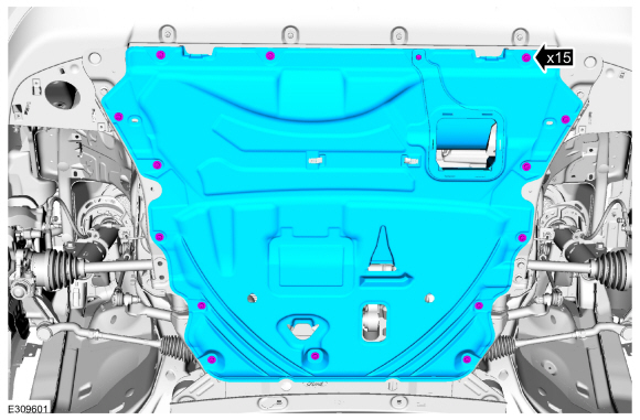
Install the undershield and fasteners.
-
-
If the engine appearance cover stud bolt is loosened or
removed, it must be installed/tightened into the valve cover.
Torque:
62 lb.in (7 Nm)
-
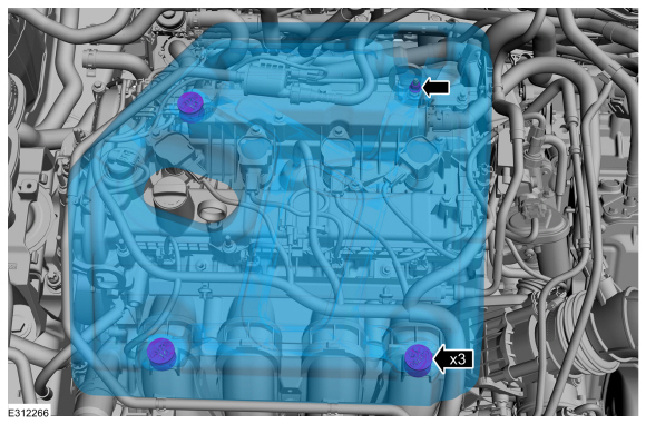
Position the engine appearance cover onto the engine with the grommets aligned with the studs.
-
Press down on the engine appearance cover at each grommet location to attach the grommets onto the studs.
-
Install the engine appearance cover nut.
Torque:
44 lb.in (5 Nm)
-
NOTE:
Use the Powertrain Control Module (PCM) Misfire Monitor Profile Correction routine in the diagnostic scan tool.
Special Tool(s) /
General Equipment
303-476
(T94P-9472-A)
Socket, Exhaust Gas Oxygen SensorTKIT-1994-LM/MTKIT-1994-FTKIT-1994-FLM/FM
Floor Crane
Adjustable Mounting Arm
Hose Clamp Remover/Installer
Fluid Container
Powertrain Jack
Wooden Block
Materials
Name
Specification
Motorcraft® High Temperature Nickel Anti-Seize LubricantXL-2
-
..
Other information:
Overview
The perimeter anti-theft alarm system has three operation modes:
ARMED - The perimeter anti-theft alarm is armed when the
ignition is OFF and all vehicle entry points have been electrically
locked for 20 seconds.
ACTIVE - When the perimeter anti-theft alarm activates,
the horn sounds and all turn signals and interior courtesy lamps flash.
The horn stops sounding after 30 s..
Wipers and Washers – Warning Lamps
Illuminates when the windshield
washer fluid is low.
Wipers and Washers – Frequently Asked Questions
Why are there streaks and smears on
the windshield?
The wiper blades could be dirty, worn
or damaged. Check the wiper blades. If the wiper blades are dirty,
clean them with washer fluid or water
applied with a soft sponge or cloth. If
the wiper blades a..
.jpg)

.jpg)
.jpg)
.jpg)
.jpg)
.jpg)

.jpg)
.jpg)
.jpg)
.jpg)
.jpg)

 Installation - Engine