Ford Escape: Power Steering / Description and Operation - Power Steering - System Operation and Component Description
System Operation
System Diagram
| Item | Description |
|---|---|
| 1 | EPAS Column |
| 2 | Motor |
| 3 | Position sensor |
| 4 | Torque sensor |
| 5 | PSCM |
| 6 | GWM |
| 7 | PCM |
| 8 | IPC |
| 9 | BCM |
| 10 | RCM |
| 11 | ABS module |
| 12 | IPMA |
| 13 | PAM |
| 14 | SCCM |
Network Message Chart
Module Network Input Messages: Power Steering Control Module (PSCM)
| Broadcast Message | Originating Module | Message Purpose |
|---|---|---|
| ABS active | ABS module | Informs the PSCM an anti-lock brake event is taking place. The PSCM modifies operating parameters when an anti-lock brake event is taking place. |
| Battery voltage | BCM | This message is sent to the GWM and then to the PSCM . Provides the PSCM with the 12-volt battery and charging system voltage. |
| Driven wheel torque output | PCM | This message is sent to the GWM and then to the PSCM . Informs the PSCM of the current torque output available at the driven wheels. This information is used for active park assist operation. |
| Ignition status | BCM | This message is sent to the GWM and then to the PSCM . Used to confirm the ignition status of the vehicle. |
| Lateral motion control data | IPMA | Contains all the lane keeping assist information necessary for EPAS lane keeping assist operation while driving through a curve. |
| Lane keep assist data | IPMA | Contains all the lane departure and lane keeping assist information necessary for EPAS lane keeping assist operation. |
| Odometer master value | IPC | This message is first sent to the GWM and then to the PSCM . The PSCM uses the odometer information for various self diagnostics. |
| Outside air temperature | IPC | This message is first sent to the GWM and then to the PSCM . The PSCM uses the temperature information for various self diagnostics. |
| Powertrain status | PCM | This message is sent to the GWM and then to the PSCM . Used to confirm the status of the operating mode; off - torque not available, on - torque not available, start in progress - torque not available or on - torque available. |
| Reverse gear status | PCM | This message is sent to the GWM and then to the PSCM . Informs the PSCM of the current reverse gear status; inactive not confirmed, inactive confirmed, active not confirmed, or active confirmed. This information is used for active park assist operation. |
| Selectable drive mode request | ABS module | Informs the PSCM of the current chassis drive mode request. |
| Stability control brake active | ABS module | Informs the PSCM either an ESC or RSC event is taking place. The PSCM modifies operating parameters when a stability control event is taking place. |
| Steering assist data | IPMA | Contains all the collision avoidance data necessary for the evasive steering feature. |
| Steering angle request | IPMA | Contains the steering angle requests for lane keeping assist operation. |
| Steering angle request | PAM | Contains the steering angle requests for parking assist operation. |
| Turn signal switch status | SCCM | Informs the PSCM of the current, driver selected turn signal switch status; off, left, or right. This message is used for lane keeping system function. |
| Vehicle configuration information | BCM | This message is sent to the GWM and then to the PSCM . Used to compare the PSCM configuration against the vehicles specific configuration (central car configuration). |
| Vehicle latitudinal acceleration rate | ABS module | Used by the PSCM for steering assist calculations. |
| Vehicle speed | ABS module | Determines the level of assist supplied to the steering gear and to validate the steering wheel component angle by comparing the rotational speeds of each wheel. The difference in the speed of each wheel is used to derive a steering angle for comparison against the EPAS motor position sensor. |
| Vehicle yaw rate | ABS module | Used by the PSCM for steering assist calculations. |
| Vehicle yaw rate | RCM | Used by the PSCM for steering assist calculations. |
| Wheel direction | ABS module | Provides the PSCM with the current direction of travel for each wheel. Used by the PSCM for steering assist calculations. |
| Wheel speed | ABS module | Provides the PSCM with the current rotational speed of each wheel. Used by the PSCM for steering assist calculations. |
EPAS System
The PSCM controls the functions of the EPAS system and communicates with other modules over the HS-CAN2 .
To activate, the PSCM requires battery voltage at the hot at all times input and battery voltage at the ignition-run input. The PSCM must also be able to communicate with other modules over the HS-CAN2 and must receive the powertrain status message from the PCM .
The main input for calculating the level of EPAS assist is the steering torque sensor signal, which is an internal component of the PSCM . Vehicle speed is also taken into consideration in order to achieve the vehicle speed dependent steering assist characteristic.
The steering shaft is composed of an input shaft and an output shaft. The two parts of the steering shaft are connected to one another via a torsion bar. When the driver turns the steering wheel, torsion occurs in the steering shaft. The amount of torsion depends on the frictional force between the tires and the road surface. The torque is increased by the use of the torsion bar, causing relative movement between the input and output shafts. This relative movement is detected by a steering shaft torque sensor and transmitted to the PSCM . The relative movement is the main parameter for calculating the control current for the EPAS motor and thus for the power assisting force. The PSCM uses a reversible motor to apply the steering assist.
The PSCM continually monitors and adjusts steering efforts based on the steering torque sensor signal, motor position and HS-CAN2 inputs to enhance the feel of the steering system. As vehicle speed increases, the amount of assist decreases to improve and enhance road feel at the steering wheel. As vehicle speed decreases, the amount of assist increases to ease vehicle maneuvering. Compensation is made to reduce the effect of pull or drift experienced when driving on roads with a high degree of camber. Compensation is also made for the impact of wheel imbalance on steering feel, up to a predetermined threshold.
The steering torque sensor senses the torque at the steering wheel. It is integrated into the PSCM and works by measuring the relative rotation between an input and output shaft which are connected by a torsion bar. The steering torque sensor sends out 2 PWM signals which allows a channel to channel cross-check and an accurate correction of the neutral point.
The PSCM is self-monitoring and is capable of setting and storing Diagnostic Trouble Codes (DTCs). Depending on the DTC set, the PSCM may enter a failure mode. In addition, the PSCM may send a request to the IPC to display a message in the message center, alerting the driver of a potential EPAS concern. The warning message is sent over the HS-CAN2 to the GWM which relays the message to the IPC over the HS-CAN3 .
Failure Modes
When a DTC is present in the PSCM , the EPAS enters 1 of 2 modes of operation.
Reduced Steering Assist Mode - The EPAS enters a reduced steering assist mode to protect the internal components of the system when a non-critical safety concern is detected by the PSCM , concerns such as low battery voltage, high battery voltage or over-temperature are considered non-critical safety concerns. This reduced steering assist mode gives the steering operation a heavier than normal feel.
Manual Steering Mode - The EPAS enters a manual steering mode (no electrical steering assistance is provided) when a concern considered to be a critical safety concern is detected. In manual steering mode, the vehicle has mechanical steering only which gives the steering operation a heavy feel.
Pull Drift Compensation (PDC)
The EPAS system has a Pull Drift Compensation (PDC) feature to assist drivers in compensating for variation in road and driving conditions. The feature adjusts power assist offset by reducing the steering wheel effort (input torque) required to keep the vehicle traveling straight. The Pull Drift Compensation (PDC) feature is automatically enabled at vehicle speeds above 40 km/h (25 mph) with sensors indicating the vehicle is traveling straight. Pull Drift Compensation (PDC) is designed to compensate for variations in road crown.
The system detects input torque to the wheel by the driver to slowly ramp in a steering assist offset to neutralize, in most situations and within limits, steering efforts for the duration of time those driving conditions exist. Full compensation requires up to 45 seconds. Changing lanes on a multilane road and the expected change in road crown would trigger a change in torque input and a compensation adjustment, and is a normal operation of the Pull Drift Compensation (PDC) feature. The feature updates automatically and continuously, however, since it is based on input torque, the feature only works with hands on the steering wheel while driving in a straight line. The system does not compensate when turning or during slight curves on highways. The system does not compensate if driver input torque, steering wheel angle or vehicle yaw rate is too large. For the system to compensate, the driver must have both hands on the steering wheel.
Active Park Assist
Some vehicles equipped with EPAS may also be equipped with active park assist. The active park assist system is controlled by the PAM and, when activated, can detect a parking space and steer the vehicle into the space by sending commands to the EPAS gear (the driver still controls the throttle, brakes and transmission). The active park assist system is comprised of several systems/modules that work together to aid in parallel parking maneuvers. The presence of certain Diagnostic Trouble Codes (DTCs) in any of those modules may either keep the active park assist system from being enabled or may disable the system if currently being used.
Refer to: Parking Aid - System Operation and Component Description
(413-13C Parking Aid - Vehicles With: Active Park Assist, Description
and Operation).
Evasive Steer Assist (ESA)
When approaching a stationary vehicle or a slower vehicle traveling in the same direction, the Evasive Steer Assist (ESA) system is designed to help the driver steer around the vehicle. If activated, the system applies additional steering torque to help the driver steer around the vehicle. After passing the vehicle, the system applies steering torque to help the driver steer back into the lane. The system deactivates after passing the vehicle.
Evasive Steer Assist (ESA) can make the steering feel lighter if the driver steers too slow and heavier if the driver steers too aggressively.
Lane Centering Assist (LCA)
NOTE: If equipped, the Lane Centering Assist (LCA) can interfere with accurate EPAS diagnostics. Disable the Lane Centering Assist (LCA) before test driving the vehicle to diagnose EPAS concerns. For information on disabling the Lane Centering Assist (LCA), refer to the Owner's Literature.
The Lane Centering Assist (LCA) utilizes the camera located in the IPMA to detect and track the road lane markings. The Lane Centering Assist (LCA) operates together with ACC . The Lane Centering Assist (LCA) assists the driver by automatically providing steering torque to help the driver keep the vehicle in the center of the lane.
Refer to: Lane Keeping System (419-07 Lane Keeping System)
.
Lane Keeping System (LKS)
NOTE: If equipped, the Lane Keeping System (LKS) can interfere with accurate EPAS diagnostics. Disable the Lane Keeping System (LKS) before test driving the vehicle to diagnose EPAS concerns. For information on disabling the Lane Keeping System (LKS), refer to the Owner's Literature.
The Lane Keeping System (LKS) uses the camera located in the IPMA to detect and track the road lane markings. The Lane Keeping System (LKS) has 2 functions, lane keeping alert and lane keeping aid. The lane keeping alert detects unintentional drifting toward the outside of the lane and alerts the driver through steering wheel vibrations and a visual alert in the IPC message center. The lane keeping aid assists the driver by automatically providing steering torque to help the driver keep the vehicle in the lane.
Refer to: Lane Keeping System (419-07 Lane Keeping System)
.
Selectable Drive Modes
The selectable drive mode system optimizes driveability and comfort as well as maximizing traction while operating on different types of terrain. The PSCM adjusts steering effort and feel based on the selected mode.
Refer to: Anti-Lock Brake System (ABS) and Stability Control -
System Operation and Component Description (206-09 Anti-Lock Brake
System (ABS) and Stability Control, Description and Operation).
Component Description
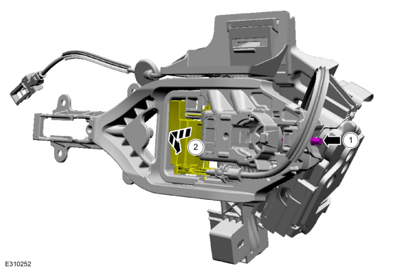
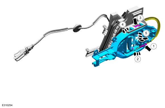
Electronic Power Assist Steering (EPAS) Column
The EPAS column is an assembly consisting of a PSCM , a variable speed reversible motor, a steering shaft torque sensor and a reduction gearset, all of which are serviced as an assembly with the steering column.
Power Steering Control Module (PSCM)
The PSCM is the ECU for the EPAS system. The module monitors all sensor inputs and HS-CAN messages that relate to the EPAS system and directly controls the output of the EPAS motor.
Reduction Gearset
The reduction gearset consists of a worm gear which is permanently attached to the steering shaft and a worm shaft connected to the rotor of the EPAS motor.
Steering Shaft Torque Sensor
The steering torque sensor is mounted in the reduction gearset and is used by the PSCM to determine how much force is being used to turn the steering wheel and in which direction the steering wheel is being turned. This is accomplished using the electromagnetic induction between the sensor stator and the sensor rotor.
 Description and Operation - Power Steering - Overview
Overview
The EPAS
system provides steering assist to the driver by replacing the
conventional, hydraulic pump system with an electric motor coupled to
the steering shaft...
 Diagnosis and Testing - Power Steering
Diagnostic Trouble Code (DTC) Chart
Diagnostics in this manual assume a certain skill level and knowledge of Ford-specific diagnostic practices. REFER to: Diagnostic Methods (100-00 General Information, Description and Operation)...
Other information:
Ford Escape 2020-2026 Service Manual: Description and Operation - Direct Current/Direct Current (DC/DC) Converter Control Module - Overview
OVERVIEW WARNING: To prevent the risk of high-voltage shock, always follow precisely all warnings and service instructions, including instructions to depower the system. The high-voltage hybrid system utilizes approximately 300 volts DC, provided through high-voltage cables to its components and modules...
Ford Escape 2020-2026 Service Manual: Description and Operation - Rear View Mirrors - Overview
Overview Exterior, Power This vehicle is equipped with LH and RH power mirrors. The power mirror system allows the exterior mirror glass to be positioned electronically. The position of the exterior mirror glass is controlled by the exterior mirror control switch and the LH or RH mirror selection buttons determine which exterior mirror glass is controlled...
Categories
- Manuals Home
- 4th Generation Ford Escape Owners Manual
- 4th Generation Ford Escape Service Manual
- Electric Parking Brake
- Drive Modes
- Accessing the Trip Computer. Resetting the Trip Computer
- New on site
- Most important about car
Adjusting the Seatbelts During Pregnancy
WARNING: Always ride and drive with your seatback upright and properly fasten your seatbelt. Fit the lap portion of the seatbelt snugly and low across the hips. Position the shoulder portion of the seatbelt across your chest. Pregnant women must follow this practice. See the following figure.
