Ford Escape 2020-2026 Service Manual / Powertrain / Engine / Engine System - General Information / General Procedures - Connecting Rod Bearing Journal Clearance
Ford Escape: Engine System - General Information / General Procedures - Connecting Rod Bearing Journal Clearance
Check
NOTE: Refer to the appropriate Section 303-01 for the specification.
-
NOTE: The crankshaft connecting rod journals must be within specifications to check the connecting rod bearing journal clearance.
Remove the connecting rod bearing cap and connecting rod bearing.
-
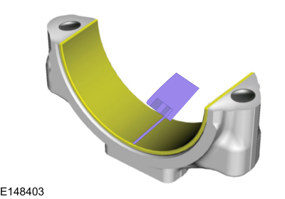
Position a piece of Plastigage across the bearing surface.
 |
-
NOTE: Do not turn the crankshaft during this step.
Install and tighten to specifications, then remove the connecting rod bearing cap.
-
Measure the Plastigage to get the connecting rod bearing
journal clearance. The Plastigage should be smooth and flat. A changing
width indicates a tapered or damaged connecting rod or connecting rod
bearing.
 |
 General Procedures - Compression and Cylinder Leakage Test - 2.5L Duratec – Hybrid (121kW/164PS) (BG)
NOTE:
The compression test requires cranking the engine a minimum of 5
compression strokes with the throttle plate in the wide-open position
for each cylinder...
 General Procedures - Crankshaft End Play
General Equipment
Dial indicator
Dial indicator fixture
NOTE:
Refer to the appropriate Section 303-01 for the specification.
Position the crankshaft to the rear of the cylinder block...
Other information:
Ford Escape 2020-2026 Service Manual: Removal and Installation - Front Stabilizer Bar
Special Tool(s) / General Equipment Tie Rod End Remover Transmission Jack Materials Name Specification Motorcraft® Metal Brake Parts CleanerPM-4-A, PM-4-B, APM-4-C - Removal NOTICE: Suspension fasteners are critical parts that affect the performance of vital components and systems...
Ford Escape 2020-2026 Service Manual: Disassembly and Assembly - Front Strut and Spring Assembly
Special Tool(s) / General Equipment Spring Compressor Vise DISASSEMBLY NOTICE: Suspension fasteners are critical parts that affect the performance of vital components and systems. Failure of these fasteners may result in major service expense...
Categories
- Manuals Home
- 4th Generation Ford Escape Owners Manual
- 4th Generation Ford Escape Service Manual
- Power Outlet - Vehicles With: 12V Power Outlet
- Drive Modes
- Adjusting the Headlamps
- New on site
- Most important about car
Fastening the Seatbelts

Copyright © 2026 www.fordescape4.com