Ford Escape: Engine System - General Information / General Procedures - Powertrain/Drivetrain Mount Neutralizing
Adjustment
All vehicles
-
With the vehicle in NEUTRAL, position it on a hoist.
Refer to: Jacking and Lifting - Overview (100-02 Jacking and Lifting, Description and Operation).
-
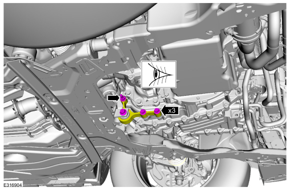
Remove the fasteners and the undershield.
1.5L & 2.0L
-
Remove the nuts and the bracket.
-
Loosen, but do not remove the roll restrictor fasteners. Verify that the roll restrictor is loose.
-
-
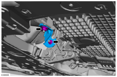
Detach the coolant hose retainer.
-
Remove the bolts and the degas bottle support bracket.
-
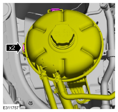
Release the tabs and position the degas bottle aside.
-
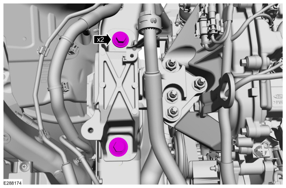
Loosen, but do not remove the engine mount bolts.
-
Remove the battery tray.
Refer to: Battery Tray - 1.5L EcoBoost (132kW/180PS) – I3 (Y1)/2.0L
EcoBoost (177kW/240PS) – MI4 (414-01 Battery, Mounting and Cables,
Removal and Installation).
-
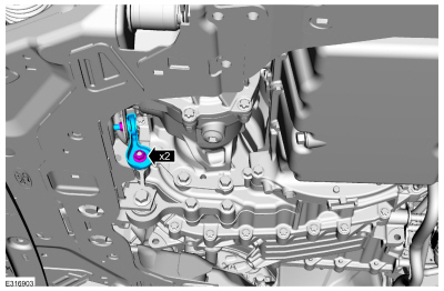
Loosen, but do not remove the transmission mount bolts.
-
Install the battery tray.
Refer to: Battery Tray - 1.5L EcoBoost (132kW/180PS) – I3 (Y1)/2.0L
EcoBoost (177kW/240PS) – MI4 (414-01 Battery, Mounting and Cables,
Removal and Installation).
2.5L
-
Remove the nuts and the bracket.
-
Loosen, but do not remove the roll restrictor fasteners. Verify that the roll restrictor is loose.
-
Disable the vehicle high-voltage electrical system.
Refer to: High Voltage System De-energizing (414-03A High Voltage Battery, Mounting and Cables, General Procedures).
-
Remove the degas bottle.
Refer to: Degas Bottle (303-03C Engine Cooling, Removal and Installation).
-
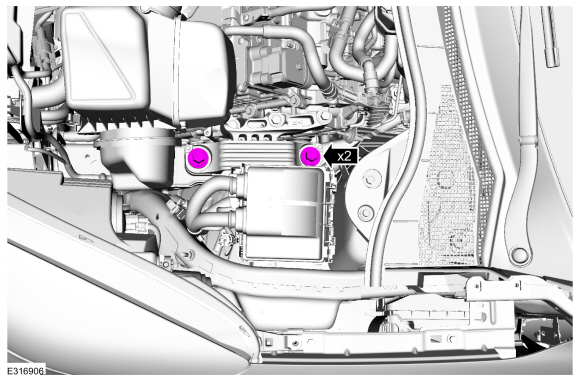
Loosen, but do not remove the engine mount bolts.
-
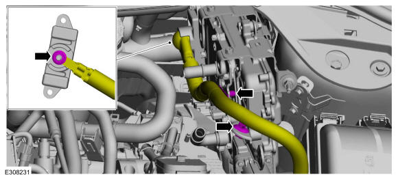
NOTE:
Be prepared to catch a minimal amount of escaping coolant fluid.
Disconnect the coolant hoses.
-
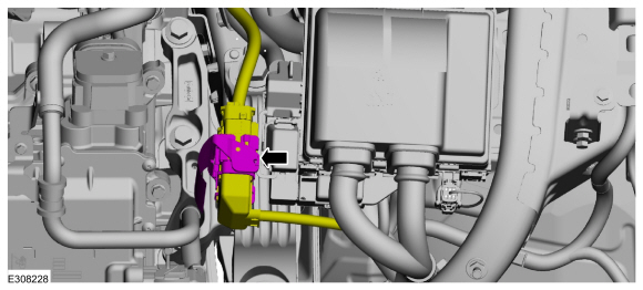
Disconnect the electrical connector and wiring harness retainers.
-
Disconnect the electrical connectors and wiring harness retainers.
-
Disconnect the electrical connector.
-
Remove wiring harness nut and disconnect the wiring harness retainers.
-
Remove the bolts and the power converter.
-
Loosen, but do not remove the transmission mount bolts.
2.5L
-
Install the power converter and the bolts.
Torque:
159 lb.in (18 Nm)
-
Connect the converter wiring harness retainers and install the wiring harness nut.
Torque:
53 lb.in (6 Nm)
-
Connect the electrical connector.
-
Connect the electrical connectors and wiring harness retainers.
-
Connect the electrical connector and wiring harness retainers.
-
Connect the coolant hoses.
-
Enable the vehicle high-voltage electrical system.
Refer to: High Voltage System De-energizing (414-03A High Voltage Battery, Mounting and Cables, General Procedures).
All vehicles
-
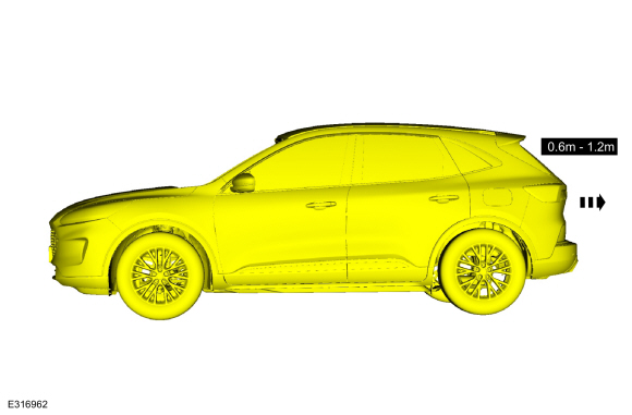
NOTE:
Do not twist or strain the powertrain/drivetrain mounts or damage to the mounts may occur.
Start the vehicle and move it forward 0.6 m (1.97 ft) - 1.2 m (3.94 ft).
-
NOTE:
Do not twist or strain the powertrain/drivetrain mounts or damage to the mounts may occur.
Move the vehicle in reverse the same distance 0.6 m (1.97 ft) - 1.2 m (3.94 ft).
2.5L
-
Disable the vehicle high-voltage electrical system.
Refer to: High Voltage System De-energizing (414-03A High Voltage Battery, Mounting and Cables, General Procedures).
-
NOTE:
Be prepared to catch a minimal amount of escaping coolant fluid.
Disconnect the coolant hoses.
-
Disconnect the electrical connector and wiring harness retainers.
-
Disconnect the electrical connectors and wiring harness retainers.
-
Disconnect the electrical connector.
-
Remove wiring harness nut and disconnect the wiring harness retainers.
-
Remove the bolts and the power converter.
1.5L & 2.0L
-
Remove the battery tray.
Refer to: Battery Tray - 1.5L EcoBoost (132kW/180PS) – I3 (Y1)/2.0L
EcoBoost (177kW/240PS) – MI4 (414-01 Battery, Mounting and Cables,
Removal and Installation).
-
Tighten the transmission mount bolts.
Torque:
Stage 1:
103 lb.ft (140 Nm)
Stage 2:
120°
-
Tighten the engine mount bolts.
Torque:
129 lb.ft (175 Nm)
-
Position the degas bottle on the tabs.
-
-
Install the degas bottle support bracket and the bolts.
-
Attach the coolant hose retainer.
-
Install the battery tray.
Refer to: Battery Tray - 1.5L EcoBoost (132kW/180PS) – I3 (Y1)/2.0L
EcoBoost (177kW/240PS) – MI4 (414-01 Battery, Mounting and Cables,
Removal and Installation).
-
-
Tighten the bolts and studbolt.
Torque:
81 lb.ft (110 Nm)
-
Tighten the bolt.
Torque:
129 lb.ft (175 Nm)
-
Install the bracket and the nuts.
Torque:
35 lb.ft (47 Nm)
2.5L
-
Tighten the engine mount bolts.
Torque:
129 lb.ft (175 Nm)
-
Install the degas bottle.
Refer to: Degas Bottle (303-03C Engine Cooling, Removal and Installation).
-
Tighten the transmission mount bolts.
Torque:
184 lb.ft (250 Nm)
-
Install the power converter and the bolts.
Torque:
159 lb.in (18 Nm)
-
Connect the converter wiring harness retainers and install the wiring harness nut.
Torque:
53 lb.in (6 Nm)
-
Connect the electrical connector.
-
Connect the electrical connectors and wiring harness retainers.
-
Connect the electrical connector and wiring harness retainers.
-
Connect the coolant hoses.
-
Remove the nuts and the bracket.
Torque:
35 lb.ft (48 Nm)
-
-
Tighten the bolts and studbolt.
Torque:
81 lb.ft (110 Nm)
-
Tighten the bolt.
Torque:
129 lb.ft (175 Nm)
-
Enable the vehicle high-voltage electrical system.
Refer to: High Voltage System De-energizing (414-03A High Voltage Battery, Mounting and Cables, General Procedures).
-
Fill the Electric Powertrain Cooling System.
Refer to: Cooling System Filling and Bleeding (303-03D Electric
Powertrain Cooling - Hybrid Electric Vehicle (HEV), General Procedures).
All vehicles
-
Install the undershield and fasteners.
-
Test the system for normal operation.
Check
NOTE:
Refer to the appropriate Section 303-01 for the specifications.
NOTE:
The cylinder bore must be within the specifications for taper and out-of-round before fitting a piston...
Special Tool(s) /
General Equipment
Plastic Scraper
Nylon Bristle Disk
Plastic Razor Blade
Lint-Free Towel
Isopropyl Alcohol – 90 Percent Minimum
Materials
Name
Specification
Motorcraft® Silicone Gasket RemoverZC-30-A, AZC-30-C
-
Motorcraft® Metal Surface Prep WipesZC-31-B
-
Motorcraft® Engine Shampoo and DegreaserZC-20, AZC-20..
Other information:
Fuse Precautions
WARNING: Always disconnect the
battery before servicing high current
fuses.
WARNING: To reduce risk of
electrical shock, always replace the
cover to the power distribution box
before reconnecting the battery or
refilling fluid reservoirs.
WARNING: Always replace a fuse
with one that has the specified
amperage rating. Using a fuse with a
higher amperage rating can cause se..
Adjustment
Vertical Alignment
NOTE:
In order to align the CCM
, the front bumper cover must be removed to access the sensor and the
vehicle must be in a wheel alignment bay station so that the vehicle is
level.
NOTE:
Damage to the CCM bracket may affect correct alignment. When aligning
the CCM , inspect the CCM bracket for damage and repair as necessary
before carrying out the ali..
.jpg)
.jpg)
.jpg)
.jpg)
.jpg)
.jpg)
.jpg)
.jpg)
.jpg)
.jpg)
.jpg)
 General Procedures - Piston Selection
 General Procedures - RTV Sealing Surface Cleaning and Preparation
 Air conditioning system