Ford Escape: Engine Emission Control / Removal and Installation - Exhaust Gas Recirculation (EGR) Outlet Tube
Special Tool(s) /
General Equipment
| Hose Clamp Remover/Installer |
Removal
-
Drain the cooling system.
Refer to: Engine Cooling System Draining, Vacuum Filling and Bleeding (303-03C Engine Cooling, General Procedures).
-
Release the fuel system pressure.
Refer to: Fuel System Pressure Release (310-00C Fuel System - General Information, General Procedures).
-
NOTE:
Do not pull the engine appearance cover forward or
sideways to remove. Failure to press straight upward on the underside of
the cover at the attachment points may result in damage to the cover or
engine components.
-
Remove the engine appearance cover nut.
-
Place your hand under the engine appearance cover at
each grommet location and push straight up to release each grommet from
the studs.
-
After all of the grommets have been released from the studs, remove the appearance cover from the engine.
-
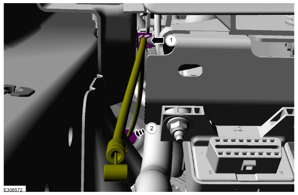
-
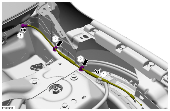
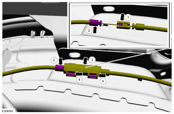
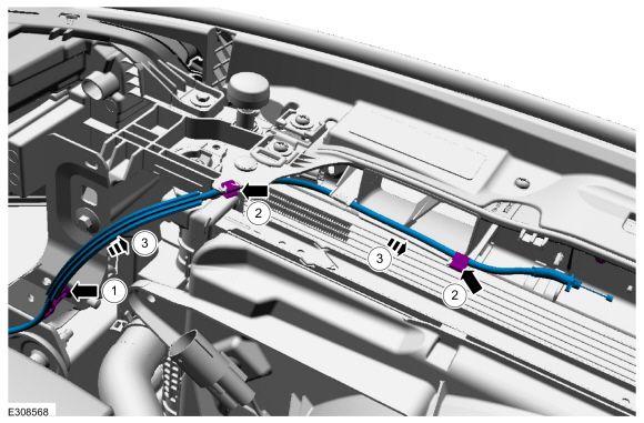
Detach the fuel hose retainer.
-
Disconnect the quick release coupling and position aside the fuel hose.
Refer to: Quick Release Coupling (310-00C Fuel System - General Information, General Procedures).
-
Remove the nut and fuel hose bracket.
-
Disconnect the quick release coupling and position aside the crankcase ventilation tube.
Refer to: Quick Release Coupling (310-00C Fuel System - General Information, General Procedures).
-
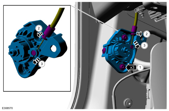
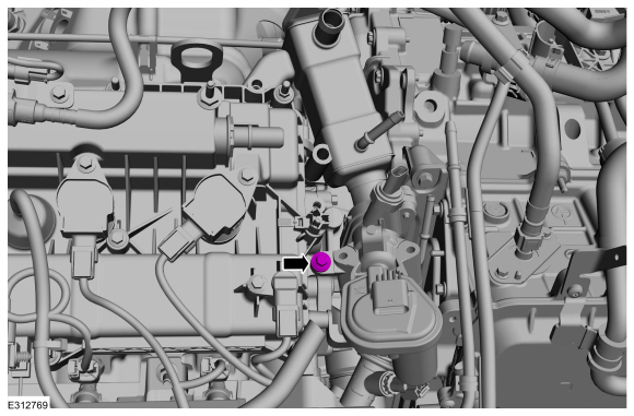
Remove the differential pressure feedback EGR sensor.
Refer to: Differential Pressure Feedback Exhaust Gas Recirculation
(EGR) Sensor (303-08C Engine Emission Control, Removal and
Installation).
-
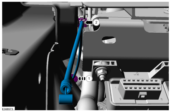
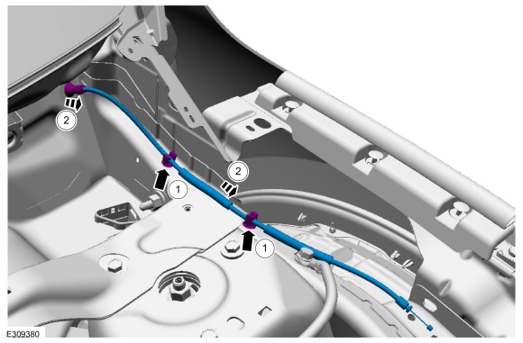
Disconnect the electrical connectors, then detach the wiring harness retainer.
-
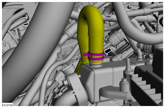
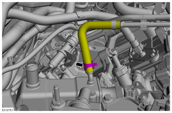
Release the clamp and disconnect the coolant hose.
Use the General Equipment: Hose Clamp Remover/Installer
-
Release the clamp and disconnect the coolant hose.
Use the General Equipment: Hose Clamp Remover/Installer
-
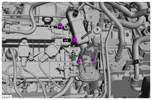
-
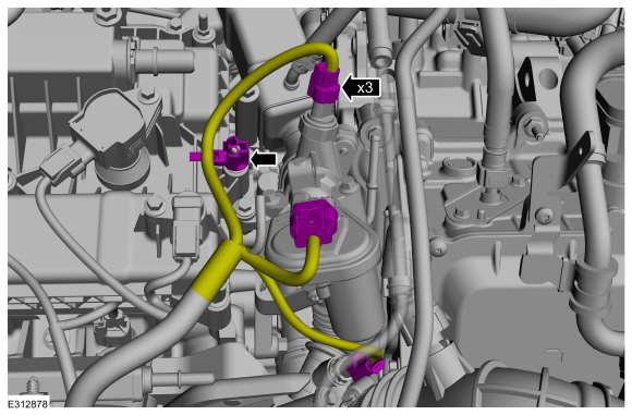
Remove the EGR cooler inlet tube bolts.
-
Remove and discard the EGR cooler inlet tube gasket.
-
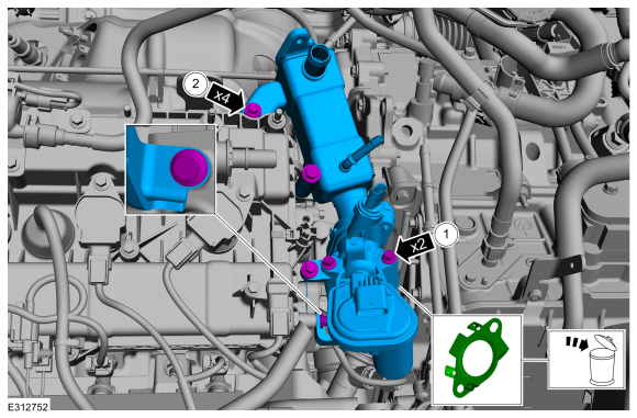
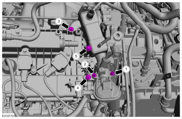
-
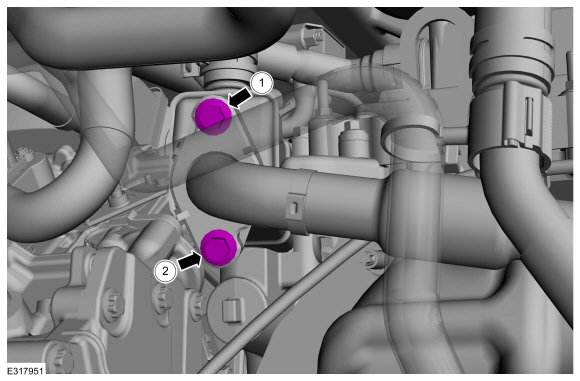
Remove the EGR outlet tube fasteners.
-
Remove the EGR mounting bolts.
-
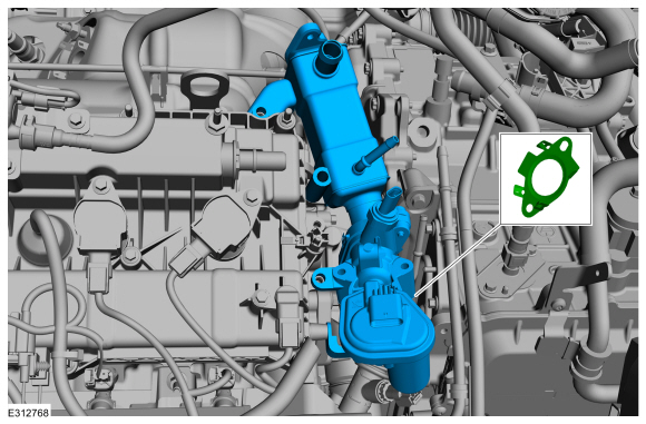
Remove and discard the EGR outlet tube gasket.
-
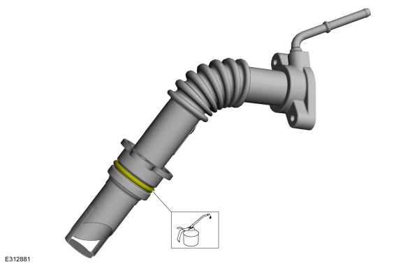
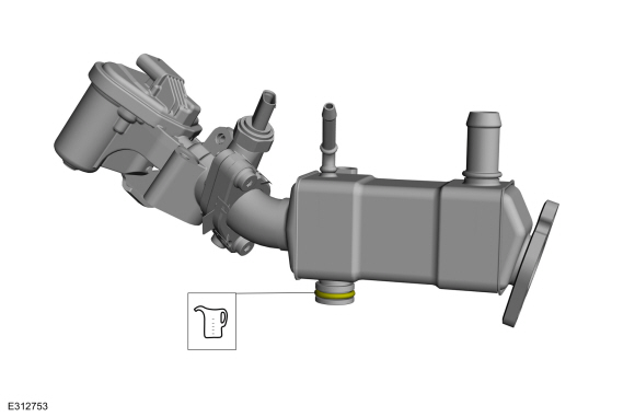
Remove and discard the EGR cooler O-ring.
-
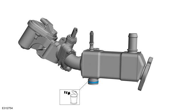
-
Remove the EGR outlet tube.
-
Remove the EGR cooler outlet temperature sensor.
-
Lubricate the o-ring seal with clean engine oil. Replace the o-ring if necessary.
-
Lubricate the o-ring seal with clean engine oil. Replace the o-ring if necessary.
Installation
-
Install the EGR cooler outlet temperature sensor.
-
-
Install the EGR outlet tube.
-
Install the fastener.
Torque:
89 lb.in (10 Nm)
-
Lubricate the new EGR cooler O-rings with a small amount of engine oil.
-
-
Install the EGR valve and EGR cooler assembly.
-
Install the EGR assembly bolt and hand tighten the bolt at this stage.
-
Install the EGR assembly mounting bolt.
Torque:
89 lb.in (10 Nm)
-
Install the EGR assembly bolts and hand tighten the bolts at this stage.
-
Tighten in the sequence shown.
Torque:
1:
89 lb.in (10 Nm)
2:
89 lb.in (10 Nm)
3:
89 lb.in (10 Nm)
4:
89 lb.in (10 Nm)
5:
18 lb.ft (25 Nm)
-
-
Hand tighten them at this stage
-
Tighten in the sequence shown.
Torque:
1:
89 lb.in (10 Nm)
2:
18 lb.ft (24 Nm)
1:
18 lb.ft (24 Nm)
-
Position back the coolant hose and the clamp.
Use the General Equipment: Hose Clamp Remover/Installer
-
Position back the coolant hose and the clamp.
Use the General Equipment: Hose Clamp Remover/Installer
-
Connect the electrical connector, then attach the wiring harness retainers.
-
Install the differential pressure feedback EGR sensor.
Refer to: Differential Pressure Feedback Exhaust Gas Recirculation
(EGR) Sensor (303-08C Engine Emission Control, Removal and
Installation).
-
Position back the crankcase ventilation tube and connect the quick release coupling.
Refer to: Quick Release Coupling (310-00C Fuel System - General Information, General Procedures).
-
Install the fuel hose bracket.
Torque:
89 lb.in (10 Nm)
-
-
Attach the fuel hose retainer.
-
Connect the quick release coupling.
Refer to: Quick Release Coupling (310-00C Fuel System - General Information, General Procedures).
-
-
If the engine appearance cover stud bolt is loosened
or removed, it must be installed/tightened into the valve cover.
Torque:
106 lb.in (12 Nm)
-
Position the engine appearance cover onto the engine with the grommets aligned with the studs.
-
Press down on the engine appearance cover at each grommet location to attach the grommets onto the studs.
-
Install the engine appearance cover nut.
Torque:
71 lb.in (8 Nm)
-
Fill and bleed the cooling system.
Refer to: Engine Cooling System Draining, Vacuum Filling and Bleeding (303-03C Engine Cooling, General Procedures).
-
Pressurize the fuel system.
Refer to: Fuel System Pressure Release (310-00C Fuel System - General Information, General Procedures).
Special Tool(s) /
General Equipment
Hose Clamp Remover/Installer
Removal
Drain the cooling system.
Refer to: Cooling System Filling and Bleeding (303-03D Electric
Powertrain Cooling - Hybrid Electric Vehicle (HEV), General Procedures)...
Special Tool(s) /
General Equipment
Hose Clamp Remover/Installer
Removal
Drain the cooling system.
Refer to: Engine Cooling System Draining, Vacuum Filling and Bleeding (303-03C Engine Cooling, General Procedures)...
Other information:
Diagnostic Trouble Code (DTC) Chart
Diagnostics in this manual assume a certain skill level and knowledge of Ford-specific diagnostic practices.REFER to: Diagnostic Methods (100-00 General Information, Description and Operation).
Module
DTC
Description
Action
PCM
P0480:00
Fan 1 Control Circuit: No Sub Type Information
GO to Pinpoint Test KN
Global Customer Symptom Code (..
Diagnostic Trouble Code (DTC) Chart
Diagnostics in this manual assume a certain skill level and knowledge of Ford-specific diagnostic practices. REFER to: Diagnostic Methods (100-00 General Information, Description and Operation).
Diagnostic Trouble Code Chart
Module
DTC
Description
Action
BCM
B1277..
.jpg)
.jpg)
.jpg)
.jpg)

 Removal and Installation - Exhaust Gas Recirculation (EGR) Cooler
 Removal and Installation - Exhaust Gas Recirculation (EGR) Valve