Ford Escape: Engine / Removal - Engine
Special Tool(s) /
General Equipment
 |
303-476
(T94P-9472-A)
Socket, Exhaust Gas Oxygen Sensor
TKIT-1994-LM/M
TKIT-1994-F
TKIT-1994-FLM/FM |
| Strap Wrench |
| Floor Crane |
| Adjustable Mounting Arm |
| Oil Drain Equipment |
| Hose Clamp Remover/Installer |
| Fluid Container |
| Punch |
| Powertrain Jack |
| Wooden Block |
| Copper Hammer |
Materials
| Name |
Specification |
Motorcraft® Penetrating and Lock Lubricant
XL-1 |
-
|
-
With the vehicle in NEUTRAL, position it on a hoist.
Refer to: Jacking and Lifting - Overview (100-02 Jacking and Lifting, Description and Operation).
-
Release the fuel system pressure.
Refer to: Fuel System Pressure Release (310-00C Fuel System - General Information, General Procedures).
-
Evacuate the A/C system.
Refer to: Air Conditioning (A/C) System Recovery, Evacuation and
Charging - 2.5L Duratec – Hybrid (121kW/164PS) (BG) (412-00 Climate
Control System - General Information, General Procedures).
Refer to: Air Conditioning (A/C) System Recovery, Evacuation
and Charging - Hybrid Electric Vehicle (HEV), Vehicles With: R134A
Refrigerant (412-00 Climate Control System - General Information - 2.5L
Duratec – Hybrid (121kW/164PS) (BG))
.
-
Depower the high-voltage system.
Refer to: High Voltage System De-energizing (414-03A High Voltage Battery, Mounting and Cables, General Procedures).
-
Disconnect the battery.
Refer to: Battery Disconnect and Connect (414-01 Battery, Mounting and Cables, General Procedures).
-
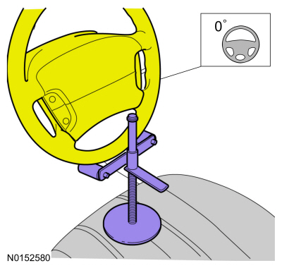
Using a holding device, hold the steering wheel in the straight-ahead position.
-
-
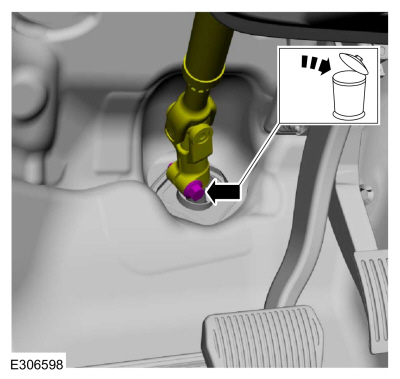
Remove the bolt and discard.
-
Position the steering column shaft aside.
-
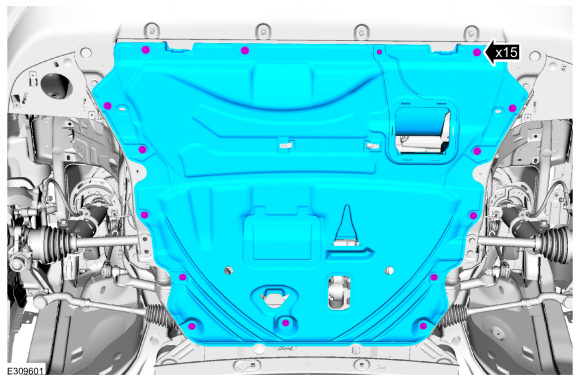
Remove the fasteners and undershield.
-
Remove the front fender splash shields.
Refer to: Fender Splash Shield (501-02 Front End Body Panels, Removal and Installation).
-
Drain the cooling system.
Refer to: Engine Cooling System Draining, Vacuum Filling and Bleeding (303-03C Engine Cooling, General Procedures).
-
Drain the Electric Powertrain Cooling system.
Refer to: Cooling System Filling and Bleeding (303-03D Electric
Powertrain Cooling - Hybrid Electric Vehicle (HEV), General Procedures).
-
-
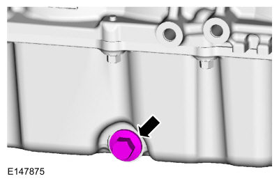
Remove the drain plug and drain the engine oil.
Use the General Equipment: Oil Drain Equipment
-
Install the drain plug.
Torque:
21 lb.ft (28 Nm)
-
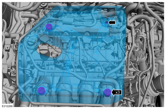
NOTE:
Do not pull the engine appearance cover forward or
sideways to remove. Failure to press straight upward on the underside of
the cover at the attachment points may result in damage to the cover or
engine components.
-
Remove the engine appearance cover nut.
-
Place your hand under the engine appearance cover at
each grommet location and push straight up to release each grommet from
the studs.
-
After all of the grommets have been released from the studs, remove the appearance cover from the engine.
-
Remove the degas bottle.
Refer to: Degas Bottle (303-03C Engine Cooling, Removal and Installation).
-
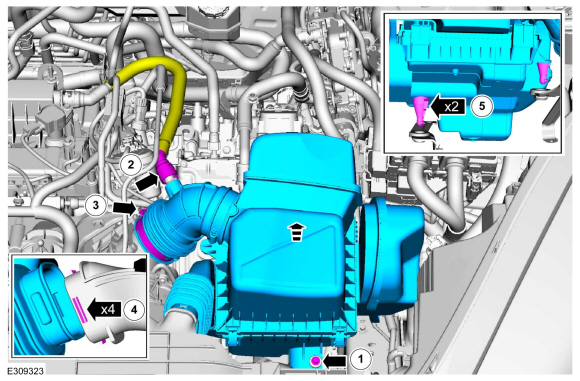
-
Remove the bolt.
-
Disconnect the vent tube.
-
Loosen the clamp.
-
Disconnect the air cleaner inlet tube.
-
Remove the air cleaner assembly.
-
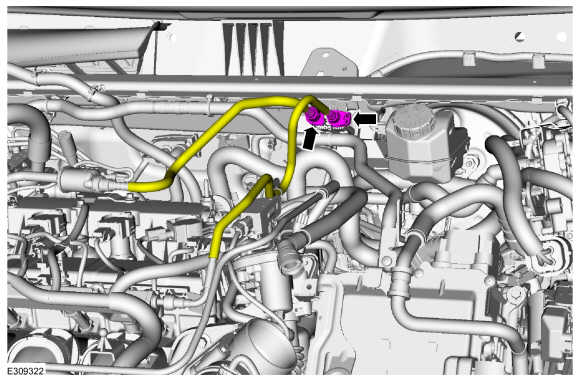
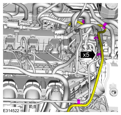
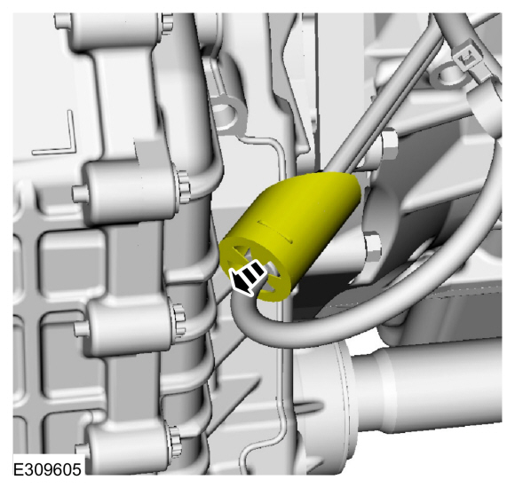
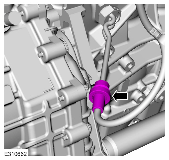
Disconnect the fuel vapor and fuel supply tubes.
Refer to: Quick Release Coupling (310-00C Fuel System - General Information, General Procedures).
Refer to: Spring Lock Couplings (310-00C Fuel System - General Information, General Procedures).
-
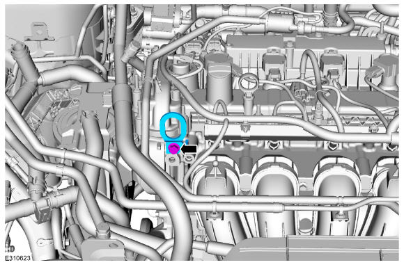
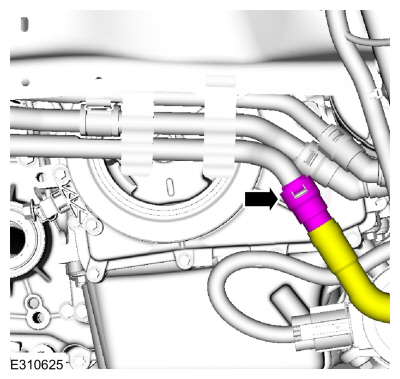
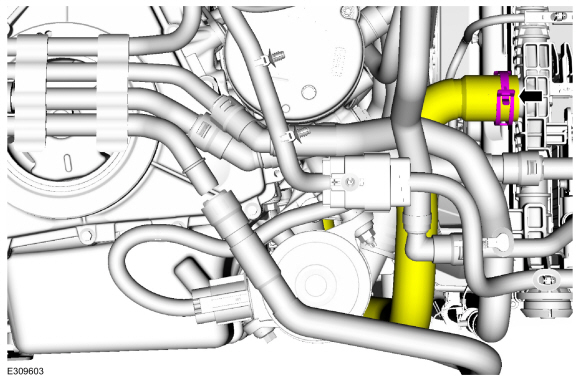
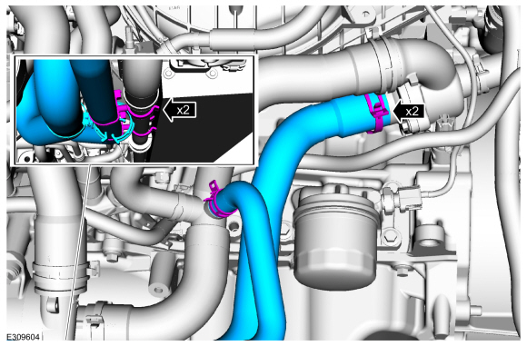
Disconnect the coolant hoses.
Use the General Equipment: Hose Clamp Remover/Installer
-
Remove the bolt and position the ground wire aside.
-
Install a commercially available lift eye.
Torque:
39 lb.ft (53 Nm)
-
If equipped.
Detach the block heater wire harness clips.
-
NOTICE:
Place tape over the connectors on the ISC (Inverter
System Controller) to prevent contaminating the connector pins.
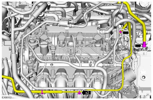
Disconnect the coolant hoses and remove the pin-type retainers.
Use the General Equipment: Hose Clamp Remover/Installer
-
Remove the nuts and the bracket.
-
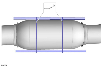
NOTE:
Do not excessively bend or twist the exhaust flexible
pipe. Failure to follow these instructions may cause damage to the
flexible pipe.
Support the exhaust flexible pipe with a support wrap or suitable splint.
-
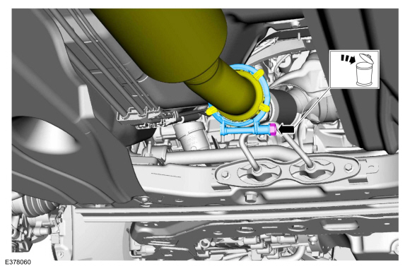
Remove and discard the outlet clamp.
-
Remove the bolts for the exhaust manifold bracket.
-
Remove the front bumper cover.
Refer to: Front Bumper Cover (501-19 Bumpers, Removal and Installation).
-
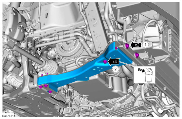
-
Remove and discard the bolts. Remove the RH subframe support bracket.
-
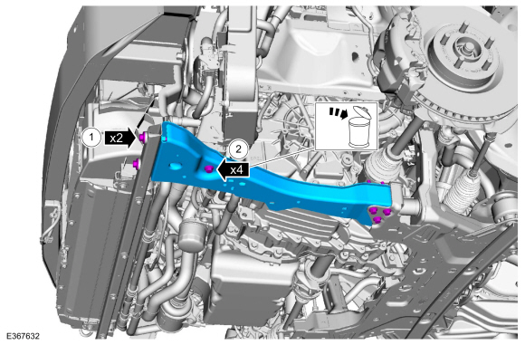
-
Remove and discard the bolts. Remove the RH subframe support bracket.
-
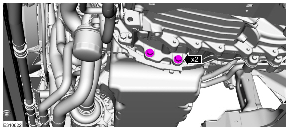
Remove the transmission to engine bolts.
-
If equipped with a block heater.
Position the block heater electrical connector cover.
-
If equipped with a block heater.
Disconnect the block heater electrical connector.
-
Disconnect the coolant hose.
Use the General Equipment: Hose Clamp Remover/Installer
-
Disconnect the coolant hose.
Use the General Equipment: Hose Clamp Remover/Installer
-
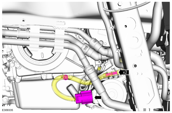
If equipped.
Disconnect the oil cooler hose.
-
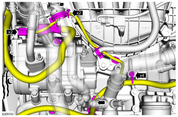
Release the clips, clamps and remove the coolant hoses.
Use the General Equipment: Hose Clamp Remover/Installer
-
Disconnect the coolant pump electrical connector and remove the wire harness retainers.
-
Disconnect the A/C electrical connectors and remove the wire harness retainers.
-
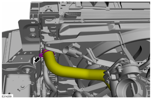
Release the clamp and disconnect the upper radiator hose.
Use the General Equipment: Hose Clamp Remover/Installer
-
NOTICE:
Place tape over the connectors on the ISC (Inverter
System Controller) to prevent contaminating the connector pins.
Disconnect the transmission converter assembly electrical connectors and remove the wire harness retainer.
-
Remove the ground wire nut, disconnect the transmission electrical connector and remove the wire harness retainers.
-
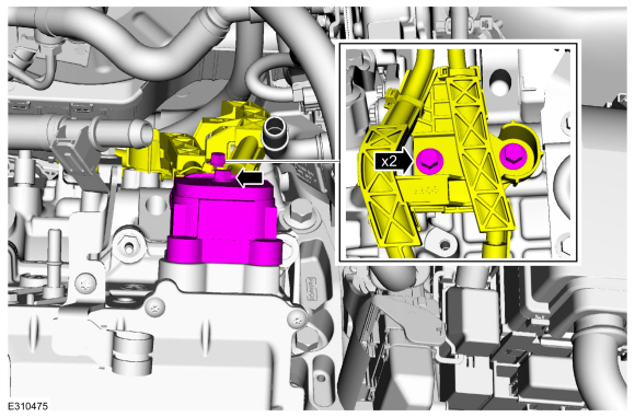
NOTICE:
Place tape over the connectors on the ISC (Inverter
System Controller) to prevent contaminating the connector pins.
Remove the bolts and disconnect the high voltage cable and position the wire harness bracket from the TCM .
-
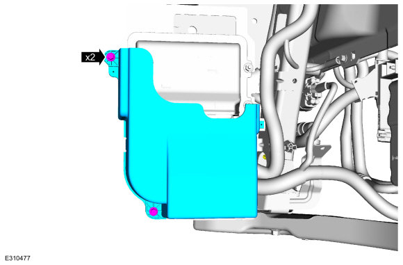
Remove the bolts and the PCM cover.
-
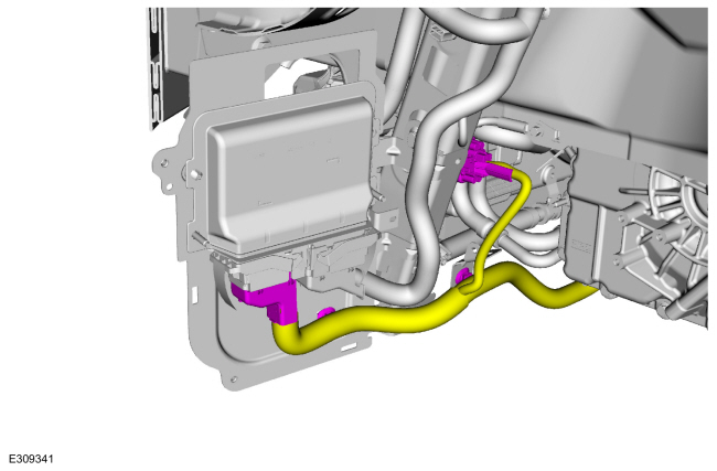
Disconnect the electrical connectors and remove the wire harness retainers.
-
NOTICE:
Place absorbent towels under the coolant connections to
prevent coolant from contacting the ISC (Inverter System Controller).
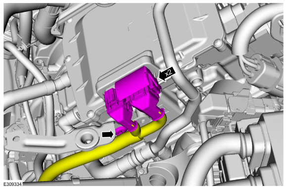
Disconnect the coolant hose.
-
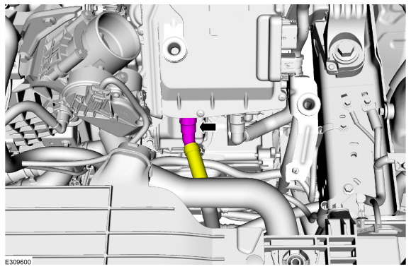
Remove the bolt and position the transmission coolant line aside.
Use the General Equipment: Fluid Container
-
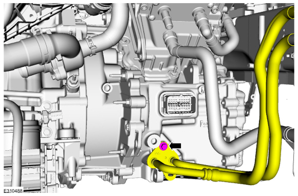
Remove the nuts and position aside the A/C line.
-
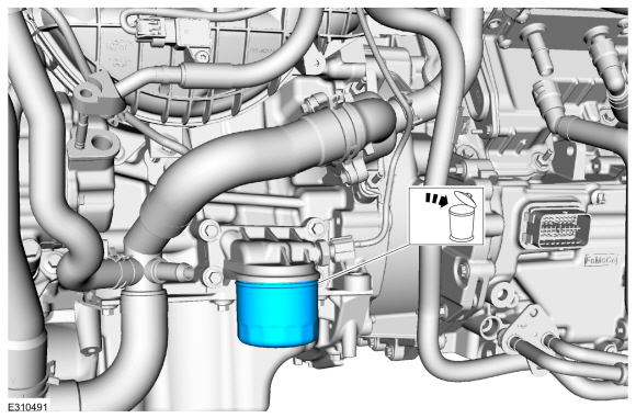
Remove and discard the engine oil filter.
Use the General Equipment: Strap Wrench
-
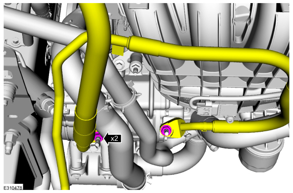
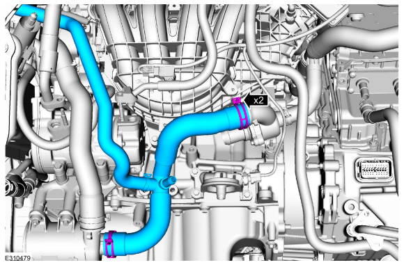
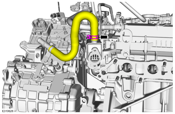
Release the clamps and remove the coolant hoses.
Use the General Equipment: Hose Clamp Remover/Installer
-
Remove the halfshaft.
Refer to: Front Halfshaft LH (205-04 Front Drive Halfshafts, Removal and Installation).
-
Remove the intermediate shaft.
Refer to: Intermediate Shaft (205-04 Front Drive Halfshafts, Removal and Installation).
-
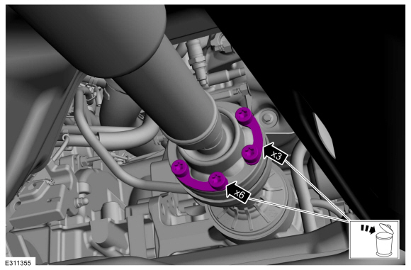
Remove and discard the driveshaft to PTU bolts and retaining straps.
-
Separate the driveshaft from the PTU flange.
-
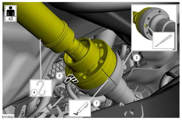
NOTE:
Make sure that the component aligns with the installation mark.
Index-mark the driveshaft and PTU flange.
-
NOTICE:
Do not remove driveshaft from the PTU flange by
pulling on the driveshaft tube. Damage to the CV-joint can result.
Using general equipment, separate the driveshaft from the PTU flange.
Use the General Equipment: Punch
Use the General Equipment: Copper Hammer
-
Position and support the driveshaft aside.
-
Disconnect the PTU temperature sensor, motor connectors and retainers.
-
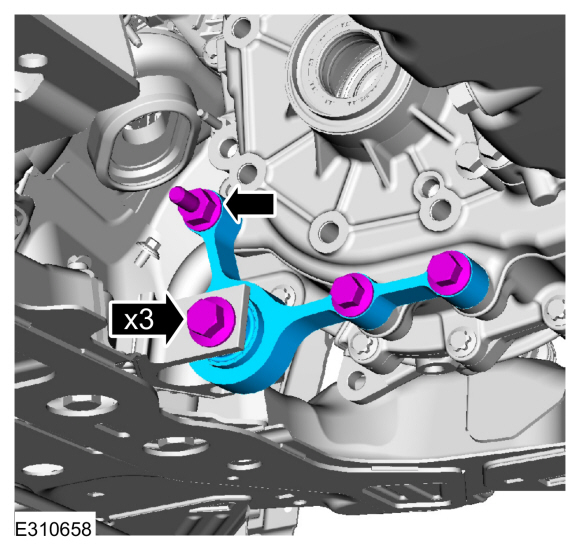
Remove the PTU support bracket bolts and the PTU support bracket.
-
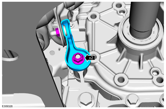
Remove the stud and bolts and the roll restictor bracket.
-
Remove the front subframe.
Refer to: Front Subframe (502-00 Uni-Body, Subframe and Mounting System, Removal and Installation).
-
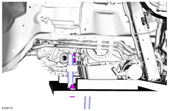
Using a Powertrain Lift and Adjustable Grip Arm, secure the engine to the lift table.
Use the General Equipment: Powertrain Jack
Use the General Equipment: Adjustable Mounting Arm
Use the General Equipment: Wooden Block
-
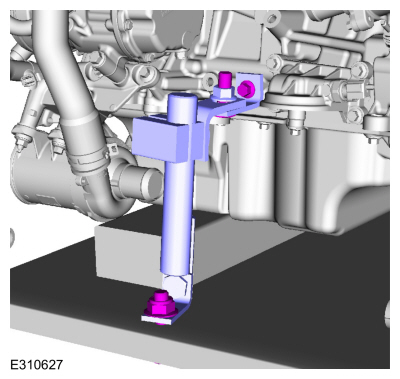
Secure the engine to the lift table.
Use the General Equipment: Powertrain Jack
Use the General Equipment: Adjustable Mounting Arm
Use the General Equipment: Wooden Block
-
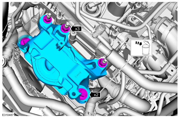
Remove the bolts, nuts and the engine mount.
-
Remove the transmission support insulator bolts.
-
Lower the engine and transmission from the vehicle.
Use the General Equipment: Powertrain Jack
Use the General Equipment: Adjustable Mounting Arm
Use the General Equipment: Wooden Block
-
-
Disconnect the HO2S electrical connector.
-
Remove the bolts and wire connector brackets.
-
Remove the HO2S .
Use Special Service Tool: 303-476
(T94P-9472-A)
Socket, Exhaust Gas Oxygen Sensor.
Material: Motorcraft® Penetrating and Lock Lubricant
/ XL-1
-
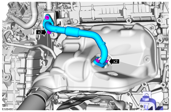
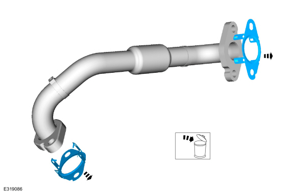
Remove the nuts, bolts and the EGR cooler inlet tube.
-
Discard the EGR cooler inlet tube gaskets.
-
Remove the bolts and the exhaust manifold heat shield.
-
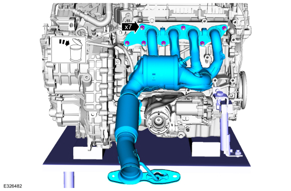
Remove the exhaust manifold and nuts. Discard the nuts.
-
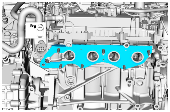
Remove and discard the exhaust manifold gasket.
-
Remove the hose from the EGR cooler.
-
Remove the vent hose retainer.
-
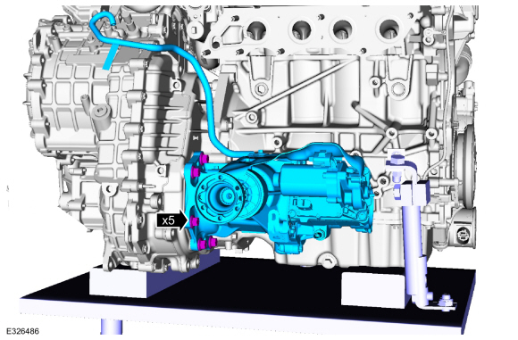
Remove the PTU bolts and the PTU.
-
Remove and discard the PTU to transmission seal.
-
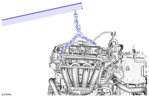
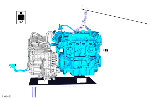
Using a Floor Crane attach a commercially available quick link and chain.
Use the General Equipment: Floor Crane
-
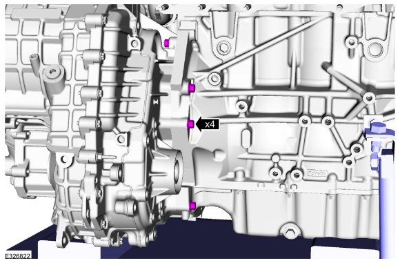
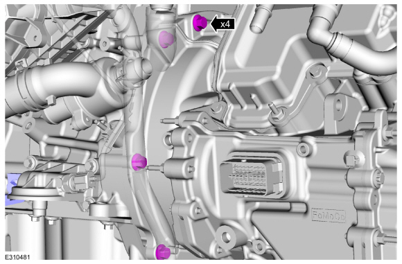
Remove the RH bolts from the engine.
-
Remove the LH bolts from the engine.
-
Remove the LH adjustable mounting arm.
Use the General Equipment: Adjustable Mounting Arm
-
Remove the RH adjustable mounting arm.
Use the General Equipment: Adjustable Mounting Arm
-
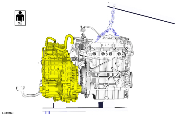
Remove the engine from the transmission.
Use the General Equipment: Floor Crane
-
Support the transmission as necessary.
Special Tool(s) /
General Equipment
205-153
(T80T-4000-W)
Handle
303-1247VCT Spark Plug Tube Seal Remover and InstallerTKIT-2006UF-FLMTKIT-2006UF-ROW
303-1416Tool, Crank Damper HoldingTKIT-2008ET-FLM
303-409
(T92C-6700-CH)
Remover, Crankshaft SealTKIT-1992-FH/FMH/FLMHTKIT-1993-LMH/MH
303-465Tool, Camshaft Align TimingTKIT-1994-LMH/MH2TKIT-1994-FH/FMH/FLMH
..
Other information:
DTC Chart
Diagnostics in this manual assume a certain skill level and knowledge of Ford-specific diagnostic practices. REFER to: Diagnostic Methods (100-00 General Information, Description and Operation).
Diagnostic Trouble Code Chart
Module
DTC
Description
Action
PCM
P0504:00
Brake Switch: A..
Removal
NOTE:
Removal steps in this procedure may contain installation details.
Remove the cowl panel grille
Refer to: Cowl Panel Grille (501-02 Front End Body Panels, Removal and Installation).
Remove the 2 LH side (under hood) instrument panel bolts
Torque:
35 lb.ft (48 Nm)
Position the manual steering column adjuster lever in t..

.jpg)
.jpg)
.jpg)
.jpg)
.jpg)
.jpg)
.jpg)
.jpg)
.jpg)
.jpg)
.jpg)
.jpg)
 Removal - Engine
 Disassembly - Engine