Ford Escape: Engine / Disassembly - Engine
Special Tool(s) /
General Equipment
.jpg) |
205-153
(T80T-4000-W)
Handle |
 |
303-1247
VCT Spark Plug Tube Seal Remover and Installer
TKIT-2006UF-FLM
TKIT-2006UF-ROW |
 |
303-1416
Tool, Crank Damper Holding
TKIT-2008ET-FLM |
.jpg) |
303-409
(T92C-6700-CH)
Remover, Crankshaft Seal
TKIT-1992-FH/FMH/FLMH
TKIT-1993-LMH/MH |
 |
303-465
Tool, Camshaft Align Timing
TKIT-1994-LMH/MH2
TKIT-1994-FH/FMH/FLMH |
 |
303-507
Timing Peg, Crankshaft TDC
TKIT-2001N-FLM
TKIT-2001N-ROW |
| Floor Crane |
| Mounting Stand |
| Plastic Scraper |
| Hose Clamp Remover/Installer |
Materials
| Name |
Specification |
Motorcraft® Silicone Gasket Remover
ZC-30-A, AZC-30-C |
-
|
Motorcraft® Metal Surface Prep Wipes
ZC-31-B |
-
|
Motorcraft® Metal Brake Parts Cleaner
PM-4-A, PM-4-B, APM-4-C |
-
|
NOTICE:
Do not loosen or remove the crankshaft pulley bolt without first
installing the special tools as instructed in this procedure. The
crankshaft pulley and the crankshaft timing sprocket are not keyed to
the crankshaft. The crankshaft, the crankshaft sprocket and the pulley
are fitted together by friction. For that reason, the crankshaft
sprocket is also unfastened if the pulley bolt is loosened. Before any
repair requiring loosening or removal of the crankshaft pulley bolt, the
crankshaft and camshafts must be locked in place by the special service
tools, otherwise severe engine damage can occur.
NOTICE:
During engine repair procedures, cleanliness is extremely
important. All parts must be thoroughly cleaned and any foreign
material, including any material created while cleaning gasket surfaces,
that enters the oil passages, coolant passages or the oil pan, can
cause engine failure.
NOTE:
If it is necessary to install a new timing chain tensioner, a
cast iron tensioner is to be replaced with an aluminum tensioner
(6K254). The existing bolts must be discarded and replaced with new
bolts (6K282).
NOTE:
Due to the precision construction of the balancer shaft assembly, it should not be disassembled.
NOTE:
For additional information, refer to the exploded views in Description and Operation in this section.
-
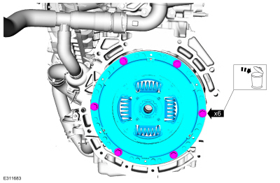
Remove the bolts and the damper. Discard the bolts.
-
-
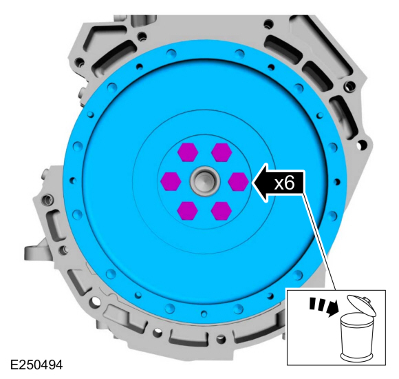
Remove the bolts and the flywheel.
-
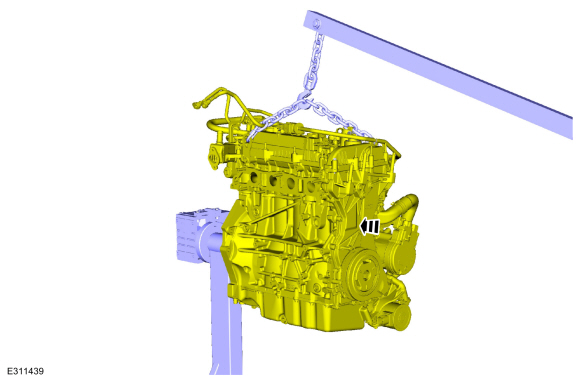
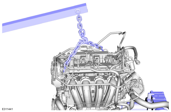
Install the engine on a mounting stand.
Use the General Equipment: Mounting Stand
-
Remove the engine lift equipment.
Use the General Equipment: Floor Crane
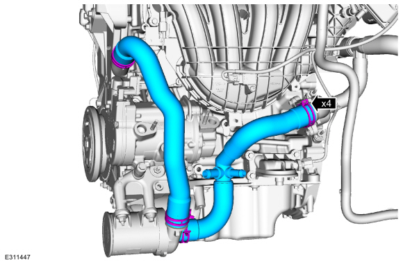
-
Remove the coolant hoses.
Use the General Equipment: Hose Clamp Remover/Installer
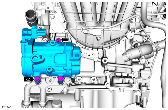
-
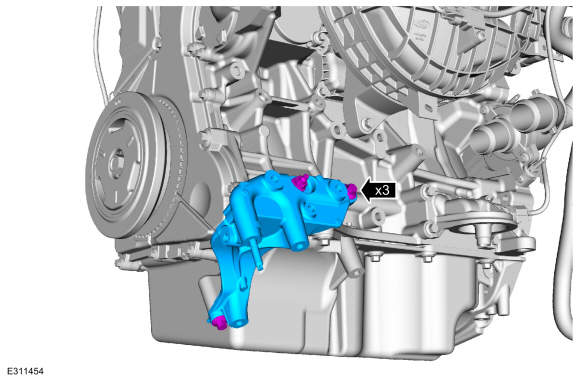
Remove the fasteners and the A/C compressor.
-
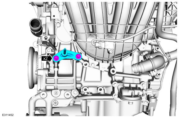
Remove the bolts and the A/C bracket.
-
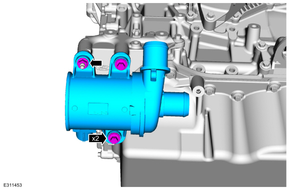
Remove the fasteners and the coolant pump.
-
Remove the fasteners and the coolant pump.
-
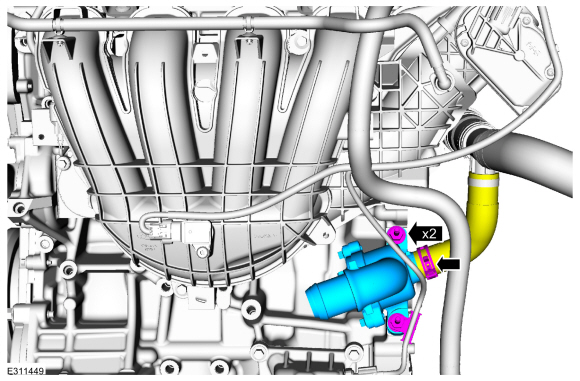
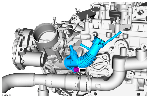
Remove the coolant hose, studs and the thermostat housing.
Use the General Equipment: Hose Clamp Remover/Installer
-
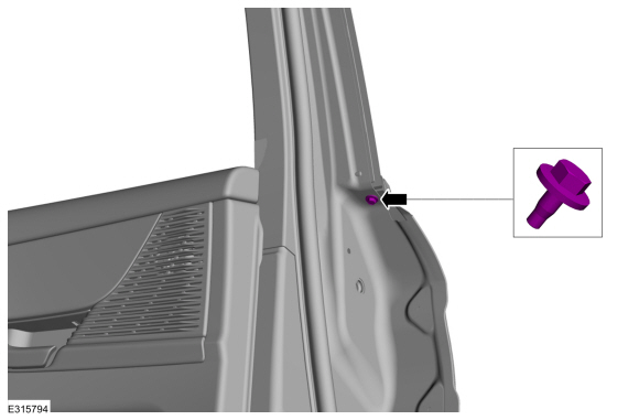
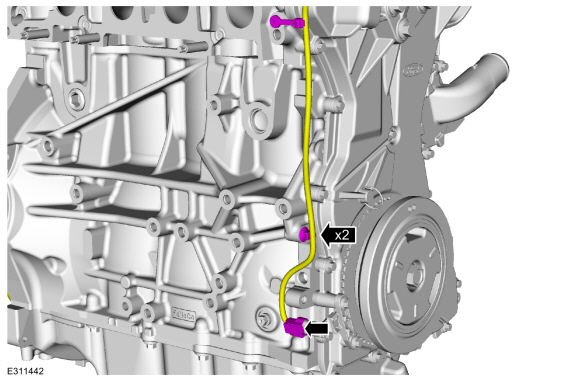
Disconnect the CKP electrical connector and detach the pin-type retainers.
-
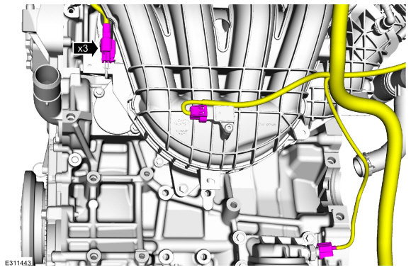
Disconnect the electrical connectors.
-
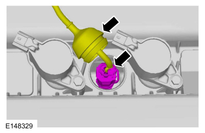
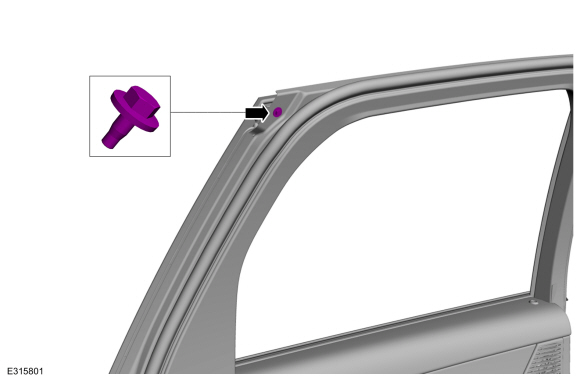
Position out the boot and disconnect the CHT sensor electrical connector.
-
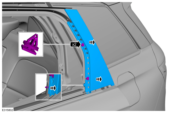
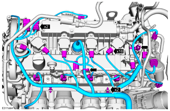
Disconnect the electrical connectors, detach the retainers and remove the wire harness.
-
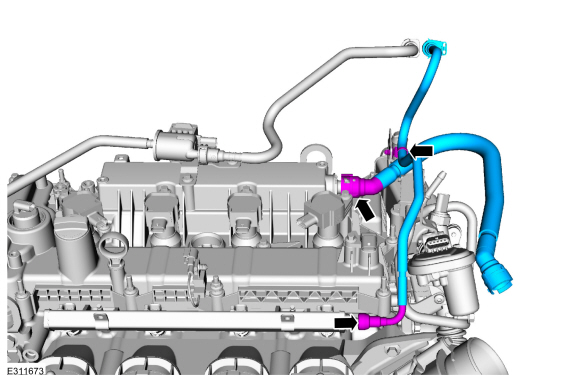
Remove the pin-type retainer, crankcase vent tube and the fuel line.
Refer to: Quick Release Coupling (310-00G)
.
Refer to: Spring Lock Couplings (310-00C Fuel System - General Information, General Procedures).
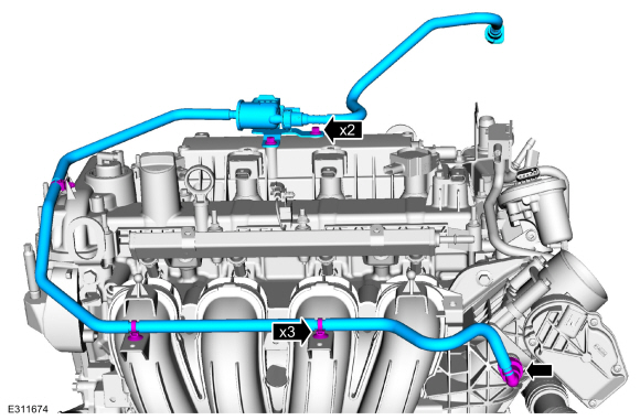
-
Remove the bolts, pin-type retainers, and the fuel vapor tube.
Refer to: Quick Release Coupling (310-00G)
.
-
Remove the nut and the fuel line bracket.
-
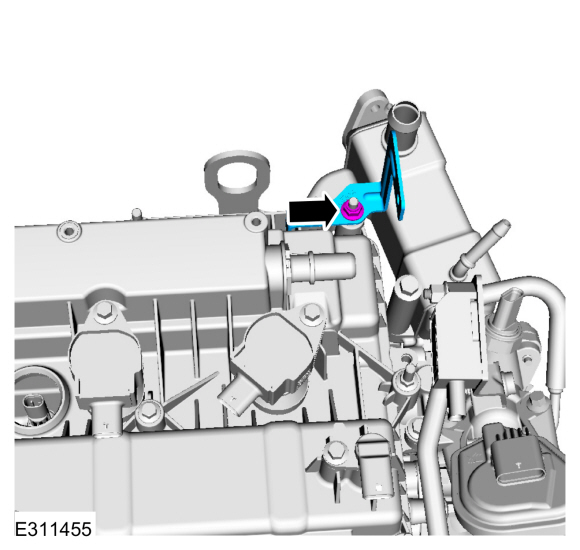
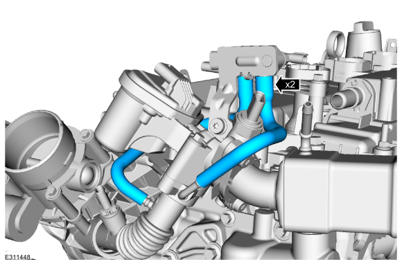
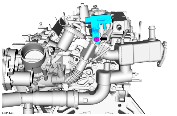
Disconnect the differential pressure sensor hoses.
-
Remove the fastener and remove the differential pressure feedback EGR sensor assembly.
-
-
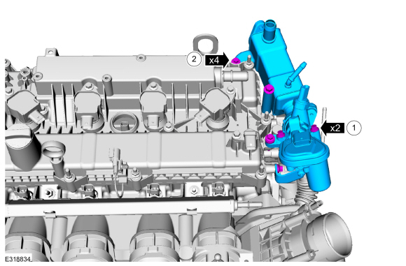
Remove the EGR outlet tube fasteners.
-
Remove the EGR mounting bolts.
-
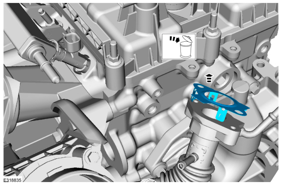
Remove and discard the EGR outlet tube gasket.
-
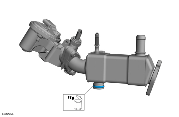
Remove and discard the EGR cooler O-ring.
-
Remove the EGR back pressure sensor.
-
-
Remove and discard the gaskets.
-
Remove the fastener and EGR outlet tube.
-
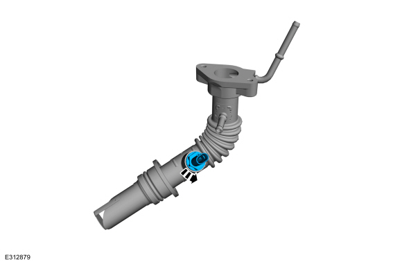
Remove the EGR cooler outlet temperature sensor.
-
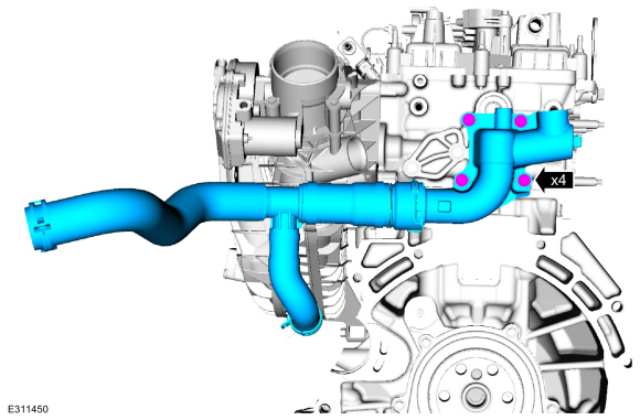
Remove the bolts, water outlet adapter and hoses.
-
NOTE:
If the engine is repaired or replaced because of upper
engine failure, typically including valve or piston damage, check the
intake manifold for metal debris. If metal debris is found, install a
new intake manifold. Failure to follow these instructions can result in
engine damage.
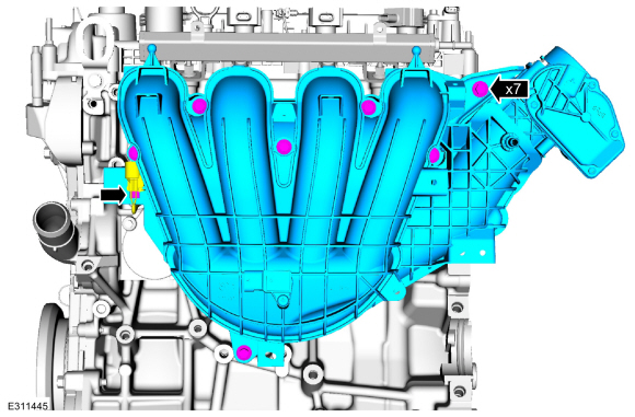
Disconnect the crankcase vent oil separator tube.
-
Detach the electrical wire pin-type retainer, remove the bolts and intake manifold.
-
-
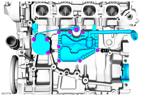
Remove the bolts and the crankcase vent oil separator.
-
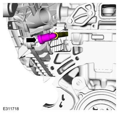
Remove the bolt and the KS .
-
Remove the bolts and the water inlet cover.
-
Remove the converter cover.
-
If equipped.
Remove the oil cooler.
-
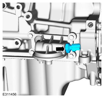
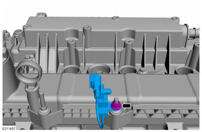
Remove the oil pressure sender.
-
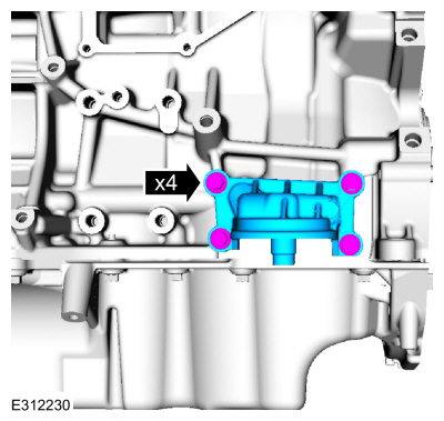
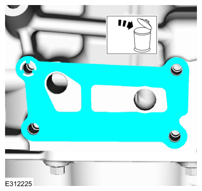
Remove the bolts and the oil filter adapter.
-
Remove and discard the gasket.
-
NOTE:
When removing the ignition coil-on-plugs, a slight twisting motion will break the seal and ease removal.
Remove the bolts and the ignition coil-on-plugs.
-
Remove the nut and the radio capacitor.
-
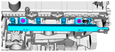
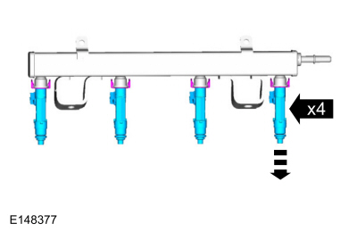
Remove the studs and the fuel rail assembly.
-
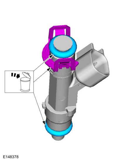
Remove the fuel injectors from the fuel rail.
-
Remove and discard the fuel injector O-ring seals and the fuel injector clips.
-
Remove the oil level indicator.
-
Remove the bolt and the cam phaser.
-
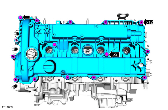
Loosen the fasteners and remove the valve cover.
-
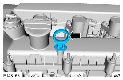
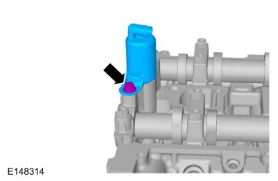
NOTE:
The VCT solenoid seal should only be replaced if it is damaged.
Using the special tools, remove the VCT oil control solenoid seals.
Use Special Service Tool: 303-1247
VCT Spark Plug Tube Seal Remover and Installer.
, 205-153
(T80T-4000-W)
Handle.
-
NOTE:
Do not use metal scrapers, wire brushes, power abrasive
discs or other abrasive means to clean the sealing surfaces. These tools
cause scratches and gouges which make leak paths.
Clean the valve cover gasket surfaces.
Material: Motorcraft® Metal Surface Prep Wipes
/ ZC-31-B
-
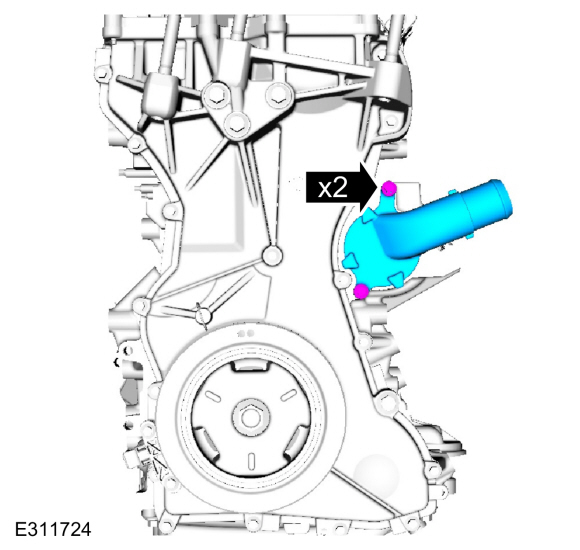
Remove the bolts and the coolant outlet assembly.
-
Remove the engine mount studs.
-
Remove the bolts and the CKP sensor.
-
Release the tabs and remove the crankshaft pulley cover.
-
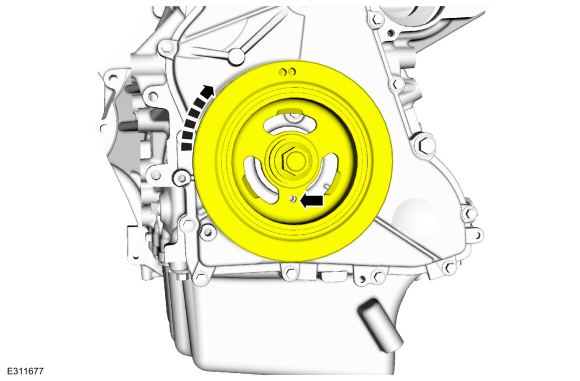
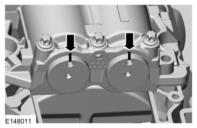
NOTE:
Failure to position the No. 1 piston at TDC can result in damage to the
engine. Turn the engine in the normal direction of rotation only.
Using the crankshaft pulley bolt, turn the crankshaft clockwise to
position the No. 1 piston at TDC . The hole in the crankshaft pulley
should be in the 6 o'clock position.
-
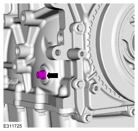
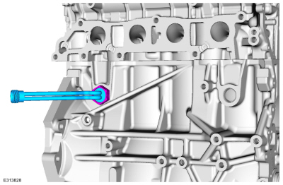
Remove the engine plug bolt.
-
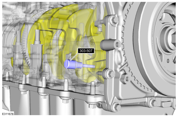
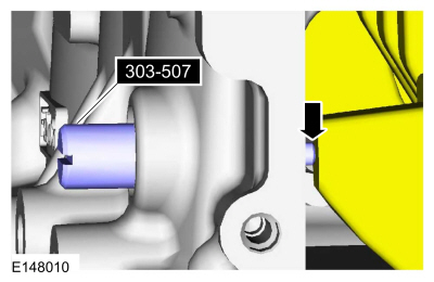
NOTE:
The Crankshaft TDC Timing Peg will contact the crankshaft and prevent
it from turning past TDC . However, the crankshaft can still be rotated
in the counterclockwise direction. The crankshaft must remain at the TDC
position during disassembly.
-
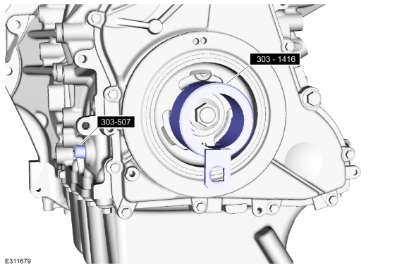
Install Special Service Tool: 303-507
Timing Peg, Crankshaft TDC.
-
Rotate the crankshaft slowly clockwise until the crankshaft balance
weight is up against the Crankshaft TDC Timing Peg. The engine is now at
TDC .
-
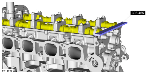
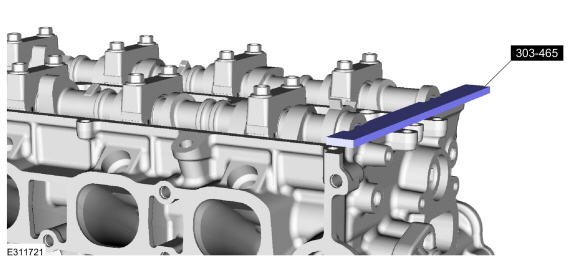
NOTE:
The Camshaft Alignment Plate is for camshaft alignment
only. Using this tool to prevent engine rotation can result in engine
damage.
NOTE:
The camshaft timing slots are offset. If the Camshaft
Alignment Plate cannot be installed, rotate the crankshaft one complete
revolution clockwise to correctly position the camshafts.
Install Special Service Tool: 303-465
Tool, Camshaft Align Timing.
-
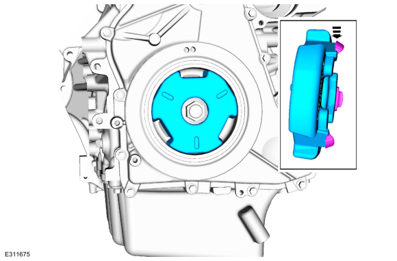
Install Suggested Tool: 303-1416
Tool, Crank Damper Holding. Tool shown or a commercially available equivalent can be used.
Use Special Service Tool: 303-507
Timing Peg, Crankshaft TDC.
-
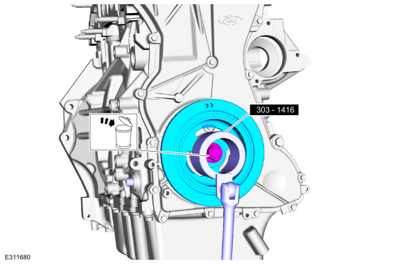
NOTICE:
The crankshaft must remain in the TDC
position during removal of the pulley bolt or damage to the engine can
occur. Therefore, the crankshaft pulley must be held in place with the
Crankshaft Damper Holding Tool and the bolt should be removed using an
air impact wrench (1/2-in drive minimum).
-
Using the special tool, remove the bolt and crankshaft pulley.
Use Special Service Tool: 303-1416
Tool, Crank Damper Holding.
-
Discard the bolt and washer.
Use Special Service Tool: 303-507
Timing Peg, Crankshaft TDC.
-
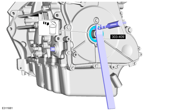
NOTE:
Use care not to damage the engine front cover or the crankshaft when removing the seal.
Using the special tool, remove and discard the crankshaft front seal.
Use Special Service Tool: 303-409
(T92C-6700-CH)
Remover, Crankshaft Seal.
, 303-507
Timing Peg, Crankshaft TDC.
-
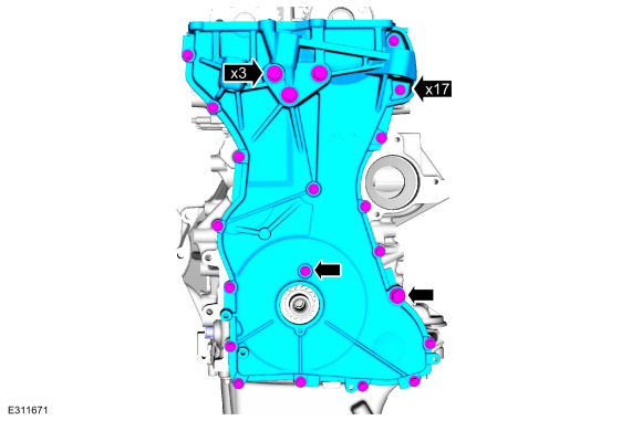
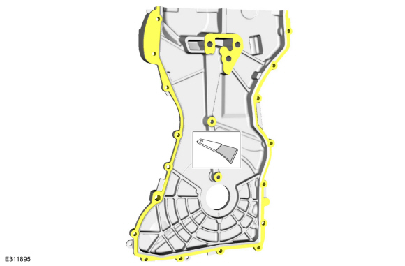
Remove the bolts and the engine front cover.
-
Make sure that the mating surface is clean and free of foreign material.
Refer to: RTV Sealing Surface Cleaning and Preparation (303-00 Engine System - General Information, General Procedures).
Use the General Equipment: Plastic Scraper
Material: Motorcraft® Silicone Gasket Remover
/ ZC-30-A, AZC-30-C
Material: Motorcraft® Metal Brake Parts Cleaner
/ PM-4-A, PM-4-B, APM-4-C
Material: Motorcraft® Metal Surface Prep Wipes
/ ZC-31-B
-
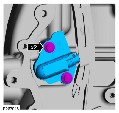
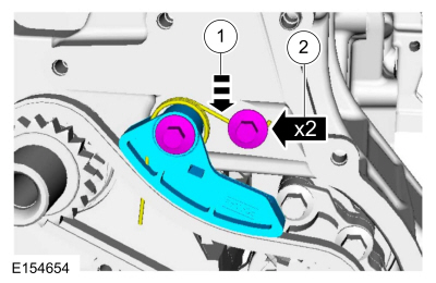
NOTE:
If equipped with aluminum timing chain tensioner.
Remove the bolts and the timing chain tensioner.
-
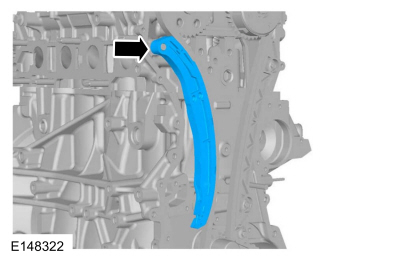
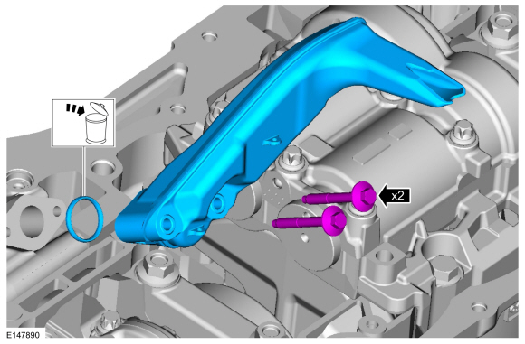
Remove the timing chain tensioner arm.
-
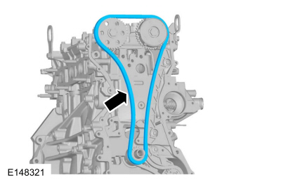
Remove the timing chain.
-
Remove the bolts and the timing chain guide.
-
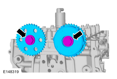
NOTE:
The Camshaft Alignment Plate is for camshaft alignment
only. Using this tool to prevent engine rotation can result in engine
damage.
NOTE:
Use the flats on the camshaft to prevent camshaft rotation.
Remove the bolts and the camshaft sprockets.
-
-
Position out the spring.
-
Remove the bolts and the oil pump chain tensioner.
-
NOTE:
The oil pump chain sprocket must be held in place.
-
Remove the chain from the oil pump drive gear.
-
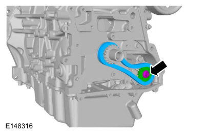
Remove the bolt and the oil pump drive gear.
-
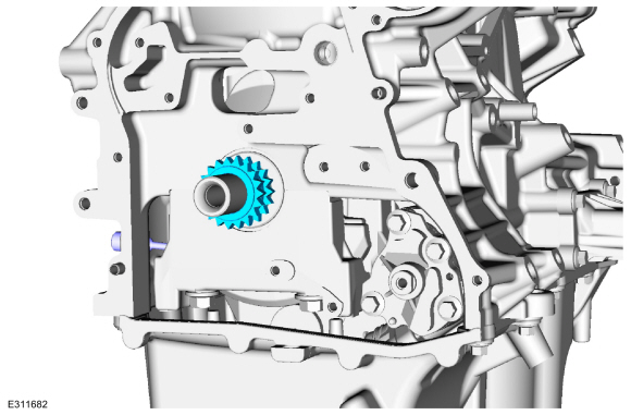
Remove the crankshaft sprocket.
Use Special Service Tool: 303-507
Timing Peg, Crankshaft TDC.
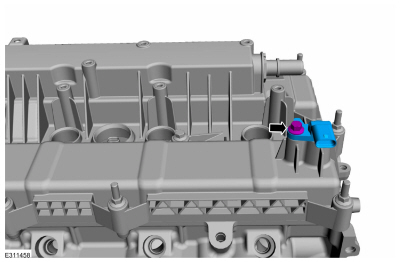
-
Remove the bolt and the VCT oil control solenoid.
-
Remove Special Service Tool: 303-465
Tool, Camshaft Align Timing.
-
NOTE:
Failure to follow the camshaft loosening procedure can result in damage to the camshafts.
NOTE:
Mark the location and orientation of each camshaft bearing cap.
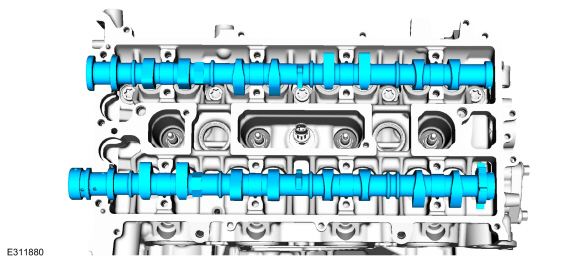
NOTE:
Mark the location of the camshafts prior to removal.
Loosen the camshaft bearing cap bolts in sequence one turn
at a time until all tension is released from the camshaft bearing caps
and remove the bolts and caps.
-
Remove the camshafts.
-
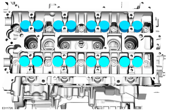
NOTE:
If the camshafts and valve tappets are to be reused,
mark the location of the valve tappets to make sure they are assembled
in their original positions.
NOTE:
The number on the valve tappets only reflects the digits
that follow the decimal. For example, a tappet with the number 0.650
has the thickness of 3.650 mm.
Remove the valve tappets.
-
Inspect the valve tappets. Install new parts as necessary.
-
Remove and discard the studs.
-
If equipped.
-
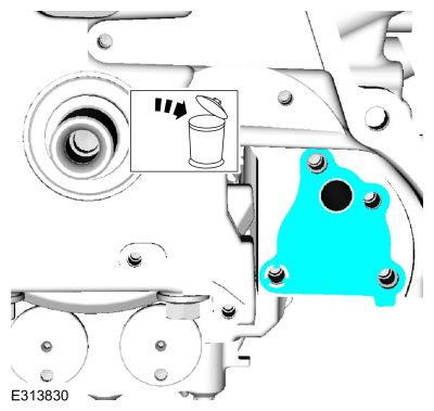
Remove the bolts and blanking plate.
-
Remove and discard the blanking plate gasket.
-
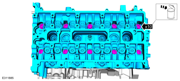
-
Remove the bolts and the cylinder head.
-
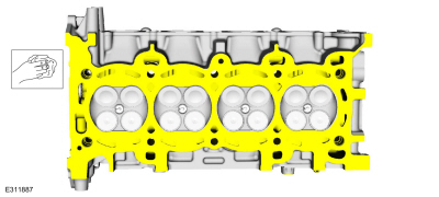
Check the cylinder head distortion.
Refer to: Cylinder Head Distortion (303-00 Engine System - General Information, General Procedures).
-
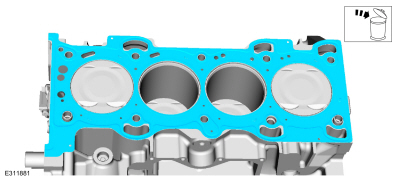
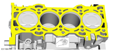
Clean the cylinder block sealing surfaces.
-
Remove and discard the cylinder head gasket.
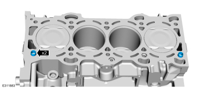
-
Remove the dowel pins.
-
NOTICE:
Do not use metal scrapers, wire brushes, power abrasive
discs or other abrasive means to clean the sealing surfaces. These
tools cause scratches and gouges that make leak paths. Use a plastic
scraping tool to remove all traces of the head gasket.
NOTE:
Clean the cylinder head bolt holes in the cylinder
block. Make sure all coolant, oil or other foreign material is removed.
Clean the cylinder block sealing surfaces.
-
Check the cylinder block distortion.
Refer to: Cylinder Block Distortion (303-00 Engine System - General Information, General Procedures).
-
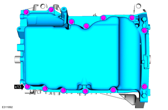
Remove the bolts and the oil pan.
-
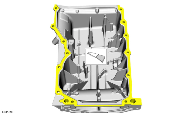
Make sure that the mating surface is clean and free of foreign material.
Refer to: RTV Sealing Surface Cleaning and Preparation (303-00 Engine System - General Information, General Procedures).
Use the General Equipment: Plastic Scraper
Material: Motorcraft® Silicone Gasket Remover
/ ZC-30-A, AZC-30-C
Material: Motorcraft® Metal Brake Parts Cleaner
/ PM-4-A, PM-4-B, APM-4-C
Material: Motorcraft® Metal Surface Prep Wipes
/ ZC-31-B
-
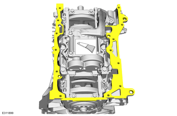
-
Remove the bolts and the oil pickup tube.
-
Remove and discard the oil pickup tube gasket.
-
-
Remove the bolts and the crankshaft rear seal.
-
Discard the crankshaft rear seal.
-
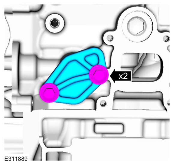
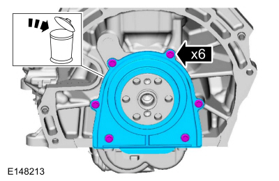
Remove the bolts and the oil pump.
-
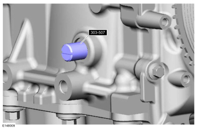
Remove and discard the oil pump gasket.
-
Make sure the Crankshaft TDC Timing Peg is still installed and the
engine is still at TDC . Rotate the crankshaft slowly clockwise until
the crankshaft balance weight is up against the Crankshaft TDC Timing
Peg.
Install Special Service Tool: 303-507
Timing Peg, Crankshaft TDC.
-
Mark the balancer unit front shafts on the top for reference that the balancer unit is at TDC .
-
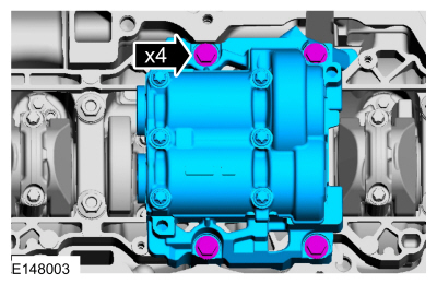
NOTE:
Due to the precision interior construction of the balancer unit, it should not be disassembled.
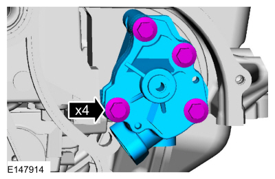
Remove the bolts and the balance shaft assembly.
-
Remove Special Service Tool: 303-507
Timing Peg, Crankshaft TDC.
-
-
Visually inspect the top of the cylinder bores.
-
Clean the specified component with the specified material.
-
General Equipment: Abrasive pad.
-
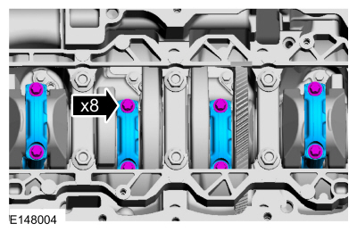
NOTE:
Clearly mark the connecting rods, connecting rod caps
and connecting rod bearings in numerical order for correct orientation
for reassembly.
Remove the bolts and the connecting rod caps.
-
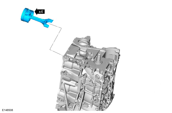
NOTE:
Do not scratch the cylinder walls or crankshaft journals with the connecting rod.
Remove the pistons.
-
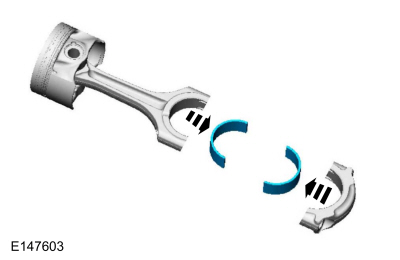
NOTE:
Mark the position of the parts, so they can be installed in their original positions.
Remove the connecting rod bearings.
-
-
Remove the bolts in sequence shown.
-
Remove the main bearing beam.
-
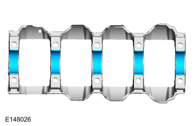
NOTE:
If the main bearings are being reused, mark them in order for correct orientation and reassembly.
Remove the lower main bearing beam bearings.
-
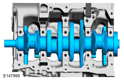
Remove the crankshaft.
-
NOTE:
If the main bearings are being reused, mark them in order for correct orientation and reassembly.
NOTE:
The center bulkhead has the thrust bearing.
Remove the upper crankshaft main bearings.
-
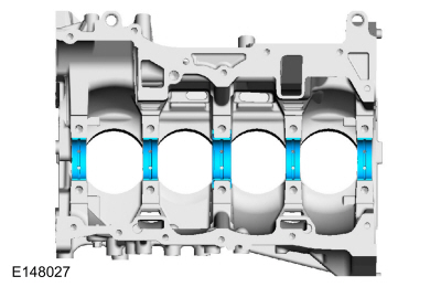
NOTE:
If the oil squirters are being reused, mark them in order for correct location during reassembly.
NOTE:
The front bulkhead does not have an oil squirter.
Remove the oil squirters.
-
Inspect the pistons.
Refer to: Piston Inspection (303-00 Engine System - General Information, General Procedures).
-
Inspect the cylinder bore taper.
Refer to: Cylinder Bore Taper (303-00 Engine System - General Information, General Procedures).
Special Tool(s) /
General Equipment
303-300
(T87C-6565-A)
Set, Valve Spring CompressorTKIT-1988-FESTIVAT88C-1000-STTKIT-1988-TRACERTKIT-2009TC-F
303-350
(T89P-6565-A)
Compressor, Valve SpringTKIT-1990-LMHTKIT-1989-FTKIT-1989-FMTKIT-1989-FLM
303-468
(T94P-6510-AH)
Remover, Valve Stem Oil SealTKIT-1994-LMH/MH2TKIT-1994-FH/FMH/FLMH
303-470
(T94P-6510-CH)
Installer,..
Other information:
Removal
WARNING:
To prevent the risk of high-voltage shock, always follow
precisely all warnings and service instructions, including instructions
to depower the system. The high-voltage system utilizes approximately
450 volts DC, provided through high-voltage cables to its components and
modules. The high-voltage cables and wiring are identified by orange
harness tape or orange wi..
Special Tool(s) /
General Equipment
Interior Trim Remover
Removal
NOTE:
Removal steps in this procedure may contain installation details.
NOTE:
The original equipment AAB
cables are part of the wiring harnesses and cannot be removed. This
procedure refers to replacement of the cable only by overlaying the
cable.
Audio front control module (ACM) to body harness cable
..
.jpg)
.jpg)
.jpg)
.jpg)
.jpg)
.jpg)
.jpg)
.jpg)
.jpg)
.jpg)
.jpg)
.jpg)
.jpg)
 Removal - Engine
 Disassembly and Assembly of Subassemblies - Cylinder Head