Ford Escape 2020-2026 Service Manual / Powertrain / Engine / Electric Powertrain Control / Description and Operation - Electric Powertrain Control - Component Location
Ford Escape: Electric Powertrain Control / Description and Operation - Electric Powertrain Control - Component Location
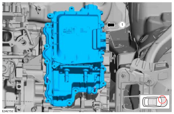
Inverter System Controller
| Item | Description |
|---|---|
| 1 | Inverter System Controller |
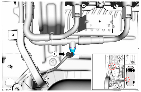
High Voltage Battery Coolant Temperature Sensor
| Item | Description |
|---|---|
| 1 | High Voltage Battery Coolant Temperature Sensor |

 Description and Operation - Electric Powertrain Control - Overview
Overview
The
center of the electric motor control system is a microprocessor called
the Inverter System Controller (ISC), also known as the SOBDMC
...
Other information:
Ford Escape 2020-2026 Service Manual: Diagnosis and Testing - Engine Temperature
Diagnostic Trouble Code (DTC) Chart Diagnostics in this manual assume a certain skill level and knowledge of Ford-specific diagnostic practices. REFER to: Diagnostic Methods (100-00 General Information, Description and Operation). Module DTC Description Action PCM P0116:00 Engine Coolant Temperature Sensor 1 Circuit Range/Performance: No Sub Type Information GO to Pinpoint Test ..
Ford Escape 2020-2026 Service Manual: General Procedures - Wheel to Hub Runout Minimization
Check NOTE: Wheel-to-hub optimization is important. Clearance between the wheel and hub can be used to offset or neutralize the Road Force® or run-out of the wheel and tire assembly. For every 0.001 inch of wheel-to-hub clearance, the Road Force® can be affected between 1 and 3 pounds depending on the tire stiffness. NOTE: The example below illustrates how the clearance betw..
Categories
- Manuals Home
- 4th Generation Ford Escape Owners Manual
- 4th Generation Ford Escape Service Manual
- Electric Parking Brake
- General Procedures - Brake Service Mode Activation and Deactivation
- Rear View Camera
- New on site
- Most important about car
Fastening the Seatbelts

Copyright © 2026 www.fordescape4.com