Ford Escape Manuals
Ford Escape 2020-2024 Service Manual / Body and Paint / Body and Paint / Rear View Mirrors / Diagnosis and Testing - Rear View Mirrors

Ford Escape: Rear View Mirrors / Diagnosis and Testing - Rear View Mirrors

Diagnostic Trouble Code (DTC) Chart

Diagnostics in this manual assume a certain skill level and knowledge of Ford-specific diagnostic practices.
REFER to: Diagnostic Methods (100-00 General Information, Description and Operation).


  Diagnostic Trouble Code Chart


Module   DTC Description Action
  DDM B1163:11 Left Mirror Heater Output: Circuit Short To Ground   GO to Pinpoint Test B
  DDM B1163:15 Left Mirror Heater Output: Circuit Short To Battery Or Open   GO to Pinpoint Test B
  DDM B1C09:01 Driver Left/Right Mirror Motor: General Electrical Failure   GO to Pinpoint Test A
  DDM B1C09:13 Driver Left/Right Mirror Motor: Circuit Open   GO to Pinpoint Test A
  DDM B1C10:01 Driver Up/Down Mirror Motor: General Electrical Failure   GO to Pinpoint Test A
  DDM B1C10:13 Driver Up/Down Mirror Motor: Circuit Open   GO to Pinpoint Test A
  DDM B1C13:12 Driver Up/Down Mirror Motor Feedback: Circuit Short To Battery   GO to Pinpoint Test C
  DDM B1C13:14 Driver Up/Down Mirror Motor Feedback: Circuit Short To Ground or Open   GO to Pinpoint Test C
  DDM B1C14:12 Driver Left/Right Mirror Motor Feedback: Circuit Short To Battery   GO to Pinpoint Test C
  DDM B1C14:14 Driver Left/Right Mirror Motor Feedback: Circuit Short To Ground or Open   GO to Pinpoint Test C
  PDM B1164:11 Right Mirror Heater Output: Circuit Short To Ground   GO to Pinpoint Test B
  PDM B1164:15 Right Mirror Heater Output: Circuit Short To Battery Or Open   GO to Pinpoint Test B
  PDM B1C11:01 Passenger Left/Right Mirror Motor: General Electrical Failure   GO to Pinpoint Test A
  PDM B1C11:13 Passenger Left/Right Mirror Motor: Circuit Open   GO to Pinpoint Test A
  PDM B1C12:01 Passenger Up/Down Mirror Motor: General Electrical Failure   GO to Pinpoint Test A
  PDM B1C12:13 Passenger Up/Down Mirror Motor: Circuit Open   GO to Pinpoint Test A
  PDM B1C15:12 Passenger Up/Down Mirror Motor Feedback: Circuit Short To Battery   GO to Pinpoint Test C
  PDM B1C15:14 Passenger Up/Down Mirror Motor Feedback: Circuit Short To Ground or Open   GO to Pinpoint Test C
  PDM B1C16:12 Passenger Left/Right Mirror Motor Feedback: Circuit Short To Battery   GO to Pinpoint Test C
  PDM B1C16:14 Passenger Left/Right Mirror Motor Feedback: Circuit Short To Ground or Open   GO to Pinpoint Test C

Global Customer Symptom Code (GCSC) Chart

Diagnostics in this manual assume a certain skill level and knowledge of Ford-specific diagnostic practices.
REFER to: Diagnostic Methods (100-00 General Information, Description and Operation).


Symptom Action
Driver Aid & Information > Blind Spot (BLIS)/Cross Traffic > Controls > Inoperative GO to Pinpoint Test J
Lighting/Glass/Vision > Mirror > Rear View > Appearance GO to Pinpoint Test K
Lighting/Glass/Vision > Mirror > Rear View > Inoperative GO to Pinpoint Test K
Lighting/Glass/Vision > Mirror > Rear View > Loose/Attachment GO to Pinpoint Test L
Lighting/Glass/Vision > Mirror > Side > Appearance GO to Pinpoint Test C
Lighting/Glass/Vision > Mirror > Side > Appearance GO to Pinpoint Test D
Lighting/Glass/Vision > Mirror > Side > Appearance GO to Pinpoint Test E
Lighting/Glass/Vision > Mirror > Side > Appearance GO to Pinpoint Test F
Lighting/Glass/Vision > Mirror > Side > Inoperative GO to Pinpoint Test A
Lighting/Glass/Vision > Mirror > Side > Inoperative GO to Pinpoint Test B
Lighting/Glass/Vision > Mirror > Side > Inoperative GO to Pinpoint Test C
Lighting/Glass/Vision > Mirror > Side > Inoperative GO to Pinpoint Test E
Lighting/Glass/Vision > Mirror > Side > Inoperative GO to Pinpoint Test G
Lighting/Glass/Vision > Mirror > Side > Loose/Attachment GO to Pinpoint Test D
Lighting/Glass/Vision > Mirror > Side > Loose/Attachment GO to Pinpoint Test M
Lighting/Glass/Vision > Mirror > Side > Loose/Attachment GO to Pinpoint Test N
Lighting/Glass/Vision > Mirror > Side > Loose/Attachment GO to Pinpoint Test O
Lighting/Glass/Vision > Mirror > Side > Manual Function GO to Pinpoint Test D
Lighting/Glass/Vision > Mirror > Side > Power Function GO to Pinpoint Test A
Lighting/Glass/Vision > Defrost > Mirror > Inoperative GO to Pinpoint Test B
Lighting/Glass/Vision > Defrost > Mirror > Inoperative GO to Pinpoint Test F
Lighting/Glass/Vision > Defrost > Mirror > Stays On GO to Pinpoint Test B
Lighting/Glass/Vision > Exterior Lighting > Turn Signal > Inoperative GO to Pinpoint Test I
Lighting/Glass/Vision > Exterior Lighting > Turn Signal > Stays On GO to Pinpoint Test I
Lighting/Glass/Vision > Exterior Lighting > Puddle > Inoperative GO to Pinpoint Test H
Lighting/Glass/Vision > Exterior Lighting > Puddle > Stays On GO to Pinpoint Test H
Lighting/Glass/Vision > Noise > Mirror > Always GO to Pinpoint Test O
Lighting/Glass/Vision > Noise > Mirror > Intermittent GO to Pinpoint Test O

Symptom Chart(s)

Diagnostics in this manual assume a certain skill level and knowledge of Ford-specific diagnostic practices.
REFER to: Diagnostic Methods (100-00 General Information, Description and Operation).

Symptom Chart: Rear View Mirrors - Exterior

Diagnostics in this manual assume a certain skill level and knowledge of Ford-specific diagnostic practices.
REFER to: Diagnostic Methods (100-00 General Information, Description and Operation).

NOTE: Clean the entire mirror assembly and glass to assist in verification of the customer concern and/or impact damage. Do not clean any mirror glass or housing with an ice scraper, razor blade, abrasive pad, harsh chemicals or petroleum based cleaning products, as these may damage the mirror glass and/or housing.

Condition Action
One or both exterior mirrors fold inward due to wind pressure   GO to Pinpoint Test D
Both exterior mirrors are inoperative (with or without memory mirrors)   GO to Pinpoint Test E
A single mirror is inoperative/does not operate correctly   GO to Pinpoint Test A
A single mirror horizontal or vertical operation does not function correctly   GO to Pinpoint Test A
The exterior mirror memory recall feature is inoperative/does not operate correctly   GO to Pinpoint Test C
One or both heated exterior mirrors are inoperative or always on   GO to Pinpoint Test B
The LH and RH heated exterior mirrors do not defrost at the same rate   GO to Pinpoint Test F
An exterior mirror selection switch LED is inoperative (exterior mirror selection switch functions normally)   GO to Pinpoint Test G
The exterior mirror puddle lamp is inoperative or always on   GO to Pinpoint Test H
The exterior mirror turn signal is inoperative or always on   GO to Pinpoint Test I
The BLIS ® indicator is inoperative or always on   GO to Pinpoint Test J

Symptom Chart: Rear View Mirrors - Interior

Diagnostics in this manual assume a certain skill level and knowledge of Ford-specific diagnostic practices.
REFER to: Diagnostic Methods (100-00 General Information, Description and Operation).

NOTE: Clean the entire mirror assembly and glass to assist in verification of the customer concern and/or impact damage. Do not clean any mirror glass or housing with an ice scraper, razor blade, abrasive pad, harsh chemicals or petroleum based cleaning products, as these may damage the mirror glass and/or housing.

Condition Action
The interior mirror is blemished   GO to Pinpoint Test K
The interior mirror vibrates or is loose   GO to Pinpoint Test L

Symptom Chart: Rear View Mirrors - Exterior Noise, Vibration and Harshness (NVH)

Diagnostics in this manual assume a certain skill level and knowledge of Ford-specific diagnostic practices.
REFER to: Diagnostic Methods (100-00 General Information, Description and Operation).

NOTE: Clean the entire mirror assembly and glass to assist in verification of the customer concern and/or impact damage. Do not clean any mirror glass or housing with an ice scraper, razor blade, abrasive pad, harsh chemicals or petroleum based cleaning products, as these may damage the mirror glass and/or housing.

Condition Action
Exterior mirror housing vibrates or is loose   GO to Pinpoint Test M
Exterior mirror glass vibrates or is loose   GO to Pinpoint Test N
Wind noise   GO to Pinpoint Test O

Pinpoint Tests

A Single Exterior Mirror Does Not Operate Correctly In All Directions


Refer to Wiring Diagrams Cell 124 for schematic and connector information.


PINPOINT TEST A: A SINGLE EXTERIOR MIRROR DOES NOT OPERATE CORRECTLY IN ALL DIRECTIONS

NOTE: Clean the entire mirror assembly and glass to assist in verification of the customer concern and/or impact damage. Do not clean any mirror glass or housing with an ice scraper, razor blade, abrasive pad, harsh chemicals or petroleum based cleaning products, as these may damage the mirror glass and/or housing.


Refer to Wiring Diagrams Cell 124 for schematic and connector information.

Normal Operation and Fault Conditions

REFER to: Rear View Mirrors - System Operation and Component Description (501-09 Rear View Mirrors, Description and Operation).

DTC Fault Trigger Conditions

DTC Description Fault Trigger Condition
DDM B1C09:01 Driver Left/Right Mirror Motor: General Electrical Failure This continuous memory and on-demand DTC is set if the DDM detects a higher than expected current draw when voltage is applied to the horizontal mirror motor circuit.
DDM B1C09:13 Driver Left/Right Mirror Motor: Circuit Open This continuous memory and on-demand DTC is sets if the DDM detects a lower than expected current draw when voltage is applied to the horizontal mirror motor circuit.
DDM B1C10:01 Driver Up/Down Mirror Motor: General Electrical Failure This continuous memory and on-demand DTC is set if the DDM detects a higher than expected current draw when voltage is applied to the vertical mirror motor circuit.
DDM B1C10:13 Driver Up/Down Mirror Motor: Circuit Open This continuous memory and on-demand DTC is sets if the DDM detects a lower than expected current draw when voltage is applied to the vertical mirror motor circuit.
PDM B1C11:01 Passenger Left/Right Mirror Motor: General Electrical Failure This continuous memory and on-demand DTC is set if the PDM detects a higher than expected current draw when voltage is applied to the horizontal mirror motor circuit.
PDM B1C11:13 Passenger Left/Right Mirror Motor: Circuit Open This continuous memory and on-demand DTC is sets if the PDM detects a lower than expected current draw when voltage is applied to the horizontal mirror motor circuit.
PDM B1C12:01 Passenger Up/Down Mirror Motor: General Electrical Failure This continuous memory and on-demand DTC is set if the PDM detects a higher than expected current draw when voltage is applied to the vertical mirror motor circuit.
PDM B1C12:13 Passenger Up/Down Mirror Motor: Circuit Open This continuous memory and on-demand DTC is sets if the PDM detects a lower than expected current draw when voltage is applied to the vertical mirror motor circuit.

Possible Sources

  • Wiring, terminals or connectors
  • Exterior mirror control switch (integral to the Driver's Side front door window control switch)
  • Exterior mirror motor
  • Exterior mirror
  • DDM
  • PDM

Visual Inspection and Pre-checks

  • Inspect the suspect exterior mirror for damage or obstructions.

NOTICE: Use the correct probe adapter(s) when making measurements. Failure to use the correct probe adapter(s) may cause damage to the connector. Use only Rotunda Flex Probes (NUD105-R025D)

A1 CHECK THE MIRROR MOVEMENT
  • Ignition ON.
  • Operate the suspect exterior mirror in the up, down, left and right directions.

Does the suspect exterior mirror operate in any direction?
Yes GO to A2
No GO to Pinpoint Test E

A2 CHECK THE EXTERIOR MIRROR CONTROL SWITCH PARAMETER IDENTIFICATIONS (PIDS)
  • Using a diagnostic scan tool, view the DDM Parameter Identifications (PIDs).
  • Using a diagnostic scan tool, view the following DDM mirror control switch Parameter Identifications (PIDs):
    • L_MIR_SEL
    • R_MIR_SEL
    • MIR_SW_DOWN
    • MIR_SW_UP
    • MIR_SW_L
    • MIR_SW_R
  • While monitoring the Parameter Identifications (PIDs), press the left mirror selection switch and press each directional control switch.
  • While monitoring the Parameter Identifications (PIDs), press the right mirror selection switch and press each directional control switch.

Do the Parameter Identifications (PIDs) agree with the mirror control switch presses?
Yes GO to A3
No INSTALL a new LH front door window control switch.
REFER to: Driver Door Window Control Switch (501-11 Glass, Frames and Mechanisms, Removal and Installation).

A3 CHECK THE VOLTAGE OUTPUT TO THE SUSPECT EXTERIOR MIRROR

NOTICE: The following step uses a test lamp to simulate normal circuit loads. Use only a Rotunda Test Lamp (SGT27000) or 250-300mA incandescent bulb test lamp. To avoid connector terminal damage, use the Rotunda Flex Probe kit for the test lamp probe connection to the vehicle. Do not use the test lamp probe directly on any connector.

  • Ignition OFF.
  • Disconnect: Suspect Exterior Mirror C521 (LH concern) or C601(RH concern).
  • Ignition ON.
  • Select the suspect exterior mirror by pressing the appropriate exterior mirror selection switch.
  • Connect:
    Click to display connectors

      LH


    Lead 1 Measurement / Action Lead 2
      C521-4   Ground
      C521-11   Ground

    Click to display connectors

      RH


    Lead 1 Measurement / Action Lead 2
      C601-4   Ground
      C601-11   Ground
  • Press the exterior mirror control switch in the left/right directions and monitor the test lamp.
  • Connect:
    Click to display connectors

      LH


    Lead 1 Measurement / Action Lead 2
      C521-14   Ground
      C521-11   Ground

    Click to display connectors

      RH


    Lead 1 Measurement / Action Lead 2
      C601-14   Ground
      C601-11   Ground
  • Press the exterior mirror control switch in the up/down directions and monitor the test lamp.

Does the test lamp illuminate only when the exterior mirror control switch is pressed in each direction?
Yes GO to A4
No GO to A5

A4 CHECK THE EXTERIOR MIRROR JUMPER HARNESS
  • Inspect the exterior mirror jumper harness between the vehicle harness and the mirror motors for:
    • Open or short circuits
    • Damaged or pushed out pins
    • Corrosion

Is the harness OK?
Yes INSTALL a new exterior mirror motor in question.
REFER to: Exterior Mirror (501-09 Rear View Mirrors, Removal and Installation).
No REPAIR the harness as necessary. If the harness cannot be repaired, INSTALL a new exterior mirror.
REFER to: Exterior Mirror (501-09 Rear View Mirrors, Removal and Installation).

A5 CHECK THE SUSPECT EXTERIOR MIRROR CIRCUITS FOR A SHORT TO VOLTAGE
  • Ignition OFF.
  • Disconnect: DDM C501B (LH concern) or PDM C652B (RH concern).
  • Ignition ON.
  • Measure:
    Click to display connectors

      LH


    Positive Lead Measurement / Action Negative Lead
      C521-4   Ground
      C521-11   Ground
      C521-14   Ground

    Click to display connectors

      RH


    Positive Lead Measurement / Action Negative Lead
      C601-4   Ground
      C601-11   Ground
      C601-14   Ground

Is any voltage present?
Yes REPAIR the circuit in question.
No GO to A6

A6 CHECK THE SUSPECT EXTERIOR MIRROR CIRCUITS FOR A SHORT TO GROUND
  • Ignition OFF.
  • Measure:
    Click to display connectors

      LH


    Positive Lead Measurement / Action Negative Lead
      C521-4   Ground
      C521-11   Ground
      C521-14   Ground

    Click to display connectors

      RH


    Positive Lead Measurement / Action Negative Lead
      C601-4   Ground
      C601-11   Ground
      C601-14   Ground

Are the resistances greater than 10,000 ohms?
Yes GO to A7
No REPAIR the circuit in question.

A7 CHECK THE SUSPECT EXTERIOR MIRROR CIRCUITS FOR AN OPEN
  • Measure:
    Click to display connectors

      LH


    Positive Lead Measurement / Action Negative Lead
      C521-4   C501B-16
      C521-11   C501B-17
      C521-14   C501B-15

    Click to display connectors

      RH


    Positive Lead Measurement / Action Negative Lead
      C601-4   C652B-16
      C601-11   C652B-17
      C601-14   C652B-15

Are the resistances less than 3 ohms?
Yes GO to A8
No REPAIR the circuit in question.

A8 CHECK FOR CORRECT DDM (DRIVER DOOR MODULE) / PDM (PASSENGER DOOR MODULE) OPERATION
  • Disconnect and inspect all DDM / PDM connectors and related in-line connectors.
  • Repair:
    • corrosion (install new connector or terminals - clean module pins)
    • damaged or bent pins - install new terminals/pins
    • pushed-out pins - install new pins as necessary
  • Reconnect the DDM / PDM connectors and related in-line connectors. Make sure they seat and latch correctly.
  • Operate the system to determine if the concern is still present.

Is the concern still present?
Yes CHECK OASIS for any applicable Technical Service Bulletins (TSBs). If a TSB exists for this concern, DISCONTINUE this test and FOLLOW the TSB instructions. If no Technical Service Bulletins (TSBs) address this concern, INSTALL a new DDM / PDM .
REFER to: Driver Door Module (DDM) (419-10 Multifunction Electronic Modules, Removal and Installation).
REFER to: Passenger Door Module (PDM) (419-10 Multifunction Electronic Modules, Removal and Installation).
No The system is operating correctly at this time. The concern may have been caused by module connections. ADDRESS the root cause of any connector or pin issues.


NOTE: The DDM and PDM automatically deactivate the heated exterior mirrors when the ambient air temperature is above 30° C (86° F).


PINPOINT TEST B: ONE OR BOTH HEATED EXTERIOR MIRRORS ARE INOPERATIVE OR ALWAYS ON (WITHOUT MEMORY MIRRORS)

NOTE: Clean the entire mirror assembly and glass to assist in verification of the customer concern and/or impact damage. Do not clean any mirror glass or housing with an ice scraper, razor blade, abrasive pad, harsh chemicals or petroleum based cleaning products, as these may damage the mirror glass and/or housing.


Refer to Wiring Diagrams Cell 124 for schematic and connector information.

Normal Operation and Fault Conditions

REFER to: Rear View Mirrors - System Operation and Component Description (501-09 Rear View Mirrors, Description and Operation).

DTC Fault Trigger Conditions

DTC Description Fault Trigger Condition
DDM B1163:11 Left Mirror Heater Output: Circuit Short To Ground This continuous and on-demand DTC sets if the DDM detects a higher than expected current draw when voltage is applied to the LH exterior mirror heater circuit.
DDM B1163:15 Left Mirror Heater Output: Circuit Short To Battery Or Open This continuous and on-demand DTC sets if the DDM detects a lower than expected current draw when voltage is applied to the LH exterior mirror heater circuit.
PDM B1164:11 Right Mirror Heater Output: Circuit Short To Ground This continuous and on-demand DTC sets if the PDM detects a higher than expected current draw when voltage is applied to the RH exterior mirror heater circuit.
PDM B1164:15 Right Mirror Heater Output: Circuit Short To Battery Or Open This continuous and on-demand DTC sets if the PDM detects a lower than expected current draw when voltage is applied to the RH exterior mirror heater circuit.

Possible Sources

  • Wiring, terminals or connectors
  • Exterior mirror glass
  • Exterior mirror
  • Door module

Visual Inspection and Pre-checks

  • Inspect the suspect exterior mirror housing and glass for damage.
B1 CHECK THE DDM (DRIVER DOOR MODULE) OR PDM (PASSENGER DOOR MODULE) DIAGNOSTIC TROUBLE CODES (DTCS)
  • Ignition ON.
  • Using a diagnostic scan tool, perform the DDM ( LH concern) or PDM ( RH concern) self-test.

Are any Diagnostic Trouble Codes (DTCs) present?
Yes • For DDM DTC B1163:11 or PDM DTC B1164:11, GO to B6
• For DDM DTC B1163:15 or PDM DTC B1164:15, GO to B2
• For all other DDM or PDM Diagnostic Trouble Codes (DTCs), REFER to the DDM or PDM DTC Chart in this section.
No GO to B2

B2 CHECK THE EXTERIOR MIRROR HEATER OUTPUT VOLTAGE AT THE INOPERATIVE EXTERIOR MIRROR

NOTICE: The following step uses a test lamp to simulate normal circuit loads. Use only a Rotunda Test Lamp (SGT27000) or 250-300mA incandescent bulb test lamp. To avoid connector terminal damage, use the Rotunda Flex Probe kit for the test lamp probe connection to the vehicle. Do not use the test lamp probe directly on any connector.

  • Ignition OFF.
  • Disconnect Exterior Mirror (LH exterior mirror) or ( RH exterior mirror).
  • Start the engine.
  • Connect:
    Click to display connectors

      LH exterior mirror


    Lead 1 Measurement / Action Lead 2
      C521-1   C521-16

    Click to display connectors

      RH exterior mirror


    Lead 1 Measurement / Action Lead 2
      C601-1   C601-16
  • NOTE: The defrost system activates for 10 minutes With the engine running, activate the rear window defrost.

Does the test light illuminate only when the rear window defrost is activated?
Yes GO to B10
No • If the test light is illuminated at all times, GO to B3
• If the test light does not illuminate, GO to B4

B3 CHECK THE HEATER CIRCUIT FOR A SHORT TO VOLTAGE AT THE EXTERIOR MIRROR
  • Ignition OFF.
  • Disconnect DDM ( LH concern) or PDM ( RH concern).
  • Ignition ON.
  • Measure:
    Click to display connectors

      LH exterior mirror


    Positive Lead Measurement / Action Negative Lead
      C521-1   Ground

    Click to display connectors

      RH exterior mirror


    Positive Lead Measurement / Action Negative Lead
      C601-1   Ground

Is any voltage present?
Yes REPAIR the circuit.
No • For the LH mirror, GO to B8
• For the RH mirror, GO to B9

B4 CHECK FOR VOLTAGE TO THE HEATER CIRCUIT AT THE EXTERIOR MIRROR

NOTICE: The following step uses a test lamp to simulate normal circuit loads. Use only a Rotunda Test Lamp (SGT27000) or 250-300mA incandescent bulb test lamp. To avoid connector terminal damage, use the Rotunda Flex Probe kit for the test lamp probe connection to the vehicle. Do not use the test lamp probe directly on any connector.

  • Turn the rear window defrost off.
  • Connect:
    Click to display connectors

      LH exterior mirror


    Lead 1 Measurement / Action Lead 2
      C521-1   Ground

    Click to display connectors

      RH exterior mirror


    Lead 1 Measurement / Action Lead 2
      C601-1   Ground
  • NOTE: The defrost system activates for 10 minutes With the engine running, activate the rear window defrost.

Does the test light illuminate?
Yes REPAIR the ground circuit.
No GO to B5

B5 CHECK FOR AN OPEN IN THE HEATER CIRCUIT BETWEEN THE MIRROR AND THE DOOR MODULE
  • Ignition OFF.
  • Disconnect DDM C501B (LH concern) or PDM C652B (RH concern).
  • Measure:
    Click to display connectors

      LH exterior mirror


    Positive Lead Measurement / Action Negative Lead
      C521-1   C501B-19

    Click to display connectors

      RH exterior mirror


    Positive Lead Measurement / Action Negative Lead
      C601-1   C652B-19

Is the resistance less than 3 ohms?
Yes • For the LH mirror, GO to B8
• For the RH mirror, GO to B9
No REPAIR the affected circuit.

B6 CHECK THE DOOR MODULE DIAGNOSTIC TROUBLE CODES (DTCS) WITH THE EXTERIOR MIRROR DISCONNECTED
  • Ignition OFF.
  • Disconnect suspect exterior mirror C517 (LH concern) or C626 (RH concern).
  • Ignition ON.
  • Using a diagnostic scan tool, clear the DDM or PDM Diagnostic Trouble Codes (DTCs).
  • Using a diagnostic scan tool, perform the DDM or PDM self-test.

Is DDM DTC B1163:15 or PDM DTC B1164:15 present?
Yes • For a LH concern, GO to B8
• For a RH concern, GO to B9
No GO to B7

B7 CHECK THE HEATER CIRCUIT FOR A SHORT TO GROUND AT THE EXTERIOR MIRROR
  • Ignition OFF.
  • Disconnect DDM C501B (LH concern) or PDM C652B (RH concern).
  • Measure:
    Click to display connectors

      LH


    Positive Lead Measurement / Action Negative Lead
      C521-1   Ground

    Click to display connectors

      RH


    Positive Lead Measurement / Action Negative Lead
      C601-1   Ground

Is the resistance greater than 10,000 ohms?
Yes GO to B10
No REPAIR the circuit.

B8 CHECK FOR CORRECT DDM (DRIVER DOOR MODULE) OPERATION
  • Ignition OFF.
  • Disconnect and inspect all DDM connectors and related in-line connectors.
  • Repair:
    • corrosion (install new connector or terminals - clean module pins)
    • damaged or bent pins - install new terminals/pins
    • pushed-out pins - install new pins as necessary
  • Reconnect the DDM connectors and related in-line connectors. Make sure they seat and latch correctly.
  • Operate the system to determine if the concern is still present.

Is the concern still present?
Yes CHECK OASIS for any applicable Technical Service Bulletins (TSBs). If a TSB exists for this concern, DISCONTINUE this test and FOLLOW the TSB instructions. If no Technical Service Bulletins (TSBs) address this concern, INSTALL a new DDM .
No The system is operating correctly at this time. The concern may have been caused by module connections. ADDRESS the root cause of any connector or pin issues.

B9 CHECK FOR CORRECT PDM (PASSENGER DOOR MODULE) OPERATION
  • Ignition OFF.
  • Disconnect and inspect all PDM connectors and related in-line connectors.
  • Repair:
    • corrosion (install new connector or terminals - clean module pins)
    • damaged or bent pins - install new terminals/pins
    • pushed-out pins - install new pins as necessary
  • Reconnect the PDM connectors and related in-line connectors. Make sure they seat and latch correctly.
  • Operate the system to determine if the concern is still present.

Is the concern still present?
Yes CHECK OASIS for any applicable Technical Service Bulletins (TSBs). If a TSB exists for this concern, DISCONTINUE this test and FOLLOW the TSB instructions. If no Technical Service Bulletins (TSBs) address this concern, INSTALL a new PDM .
No The system is operating correctly at this time. The concern may have been caused by module connections. ADDRESS the root cause of any connector or pin issues.

B10 CHECK THE EXTERIOR MIRROR JUMPER HARNESS
  • Inspect the exterior mirror jumper harness between the vehicle harness and the mirror glass for:
    • Open or short circuits
    • Damaged or pushed out pins
    • Corrosion

Is the harness OK?
Yes INSTALL a new exterior mirror glass.
No REPAIR the harness as necessary. If the harness cannot be repaired, INSTALL a new exterior mirror.

PINPOINT TEST C: THE EXTERIOR MIRROR MEMORY RECALL FEATURE IS INOPERATIVE/DOES NOT OPERATE CORRECTLY

NOTE: Clean the entire mirror assembly and glass to assist in verification of the customer concern and/or impact damage. Do not clean any mirror glass or housing with an ice scraper, razor blade, abrasive pad, harsh chemicals or petroleum based cleaning products, as these may damage the mirror glass and/or housing.


Refer to Wiring Diagrams Cell 124 for schematic and connector information.

Normal Operation and Fault Conditions

REFER to: Rear View Mirrors - System Operation and Component Description (501-09 Rear View Mirrors, Description and Operation).

DTC Fault Trigger Conditions

DTC Description Fault Trigger Condition
DDM B1C13:12 Driver Up/Down Mirror Motor Feedback: Circuit Short To Battery A continuous and on-demand DTC that sets in the DDM if the DDM detects a short to battery from the vertical position feedback circuit.
DDM B1C13:14 Driver Up/Down Mirror Motor Feedback: Circuit Short To Ground Or Open A continuous and on-demand DTC that sets in the DDM if the DDM detects a short to ground or open from the vertical position feedback circuit.
DDM B1C14:12 Driver Left/Right Mirror Motor Feedback: Circuit Short To Battery A continuous and on-demand DTC that sets in the DDM if the DDM detects a short to battery from the horizontal position feedback circuit.
DDM B1C14:14 Driver Left/Right Mirror Motor Feedback: Circuit Short To Ground Or Open A continuous and on-demand DTC that sets in the DDM if the DDM detects a short to ground or open from the horizontal position feedback circuit.
PDM B1C15:12 Passenger Up/Down Mirror Motor Feedback: Circuit Short To Battery A continuous and on-demand DTC that sets in the PDM if the PDM detects a short to battery from the vertical position feedback circuit.
PDM B1C15:14 Passenger Up/Down Mirror Motor Feedback: Circuit Short To Ground Or Open A continuous and on-demand DTC that sets in the PDM if the PDM detects a short to ground or open from the vertical position feedback circuit.
PDM B1C16:12 Passenger Left/Right Mirror Motor Feedback: Circuit Short To Battery A continuous and on-demand DTC that sets in the PDM if the PDM detects a short to battery from the horizontal position feedback circuit.
PDM B1C16:14 Passenger Left/Right Mirror Motor Feedback: Circuit Short To Ground Or Open A continuous and on-demand DTC that sets in the PDM if the PDM detects a short to ground or open from the horizontal position feedback circuit.

Possible Sources

  • Wiring, terminals or connectors
  • EMemory seat system concern
  • Power mirror system concern
  • Exterior mirror motor
  • Exterior mirror
  • DDM
  • PDM

Visual Inspection and Pre-checks

  • Inspect the suspect exterior mirror for damage or obstructions.

NOTICE: Use the correct probe adapter(s) when making measurements. Failure to use the correct probe adapter(s) may cause damage to the connector. Use only Rotunda Flex Probes (NUD105-R025D)

C1 CHECK THE MEMORY SEAT OPERATION
  • Ignition ON.
  • Check the operation of the memory seat recall function.

Does the memory seat recall function operate?
Yes GO to C2
No DIAGNOSE the memory seat system prior to continuing diagnostics for the exterior mirror memory recall feature.
REFER to: Front Seats (501-10A Front Seats, Diagnosis and Testing).

C2 CHECK THE POWER MIRRORS OPERATION
  • Check the operation of the of the up/down and left/right function of the suspect power mirrors.

Does the suspect mirror operate in all directions?
Yes GO to C3
No GO to Pinpoint Test A

C3 CHECK THE SUSPECT EXTERIOR MIRROR POSITION SENSOR CIRCUITS FOR A SHORT TO VOLTAGE
  • Ignition OFF.
  • Disconnect: Suspect Exterior Mirror C521 (LH concern) or C601(RH concern).
  • Disconnect: DDM C501B (LH concern) or PDM C652B (RH concern).
  • Ignition ON.
  • Measure:
    Click to display connectors

      LH


    Positive Lead Measurement / Action Negative Lead
      C521-6   Ground
      C521-9   Ground
      C521-12   Ground
      C521-13   Ground

    Click to display connectors

      RH


    Positive Lead Measurement / Action Negative Lead
      C601-6   Ground
      C601-9   Ground
      C601-12   Ground
      C601-13   Ground

Is any voltage present?
Yes REPAIR the circuit in question.
No GO to C4

C4 CHECK THE SUSPECT EXTERIOR MIRROR POSITION SENSOR CIRCUITS FOR A SHORT TO GROUND
  • Ignition OFF.
  • Measure:
    Click to display connectors

      LH


    Positive Lead Measurement / Action Negative Lead
      C521-6   Ground
      C521-9   Ground
      C521-12   Ground
      C521-13   Ground

    Click to display connectors

      RH


    Positive Lead Measurement / Action Negative Lead
      C601-6   Ground
      C601-9   Ground
      C601-12   Ground
      C601-13   Ground

Are the resistances greater than 10,000 ohms?
Yes GO to C5
No REPAIR the circuit in question.

C5 CHECK THE SUSPECT EXTERIOR MIRROR POSITION SENSOR CIRCUITS FOR AN OPEN
  • Measure:
    Click to display connectors

      LH


    Positive Lead Measurement / Action Negative Lead
      C521-6   C501B-23
      C521-9   C501B-10
      C521-12   C501B-22
      C521-13   C501B-21

    Click to display connectors

      RH


    Positive Lead Measurement / Action Negative Lead
      C601-6   C652B-23
      C601-9   C652B-10
      C601-12   C652B-22
      C601-13   C652B-21

Are the resistances less than 3 ohms?
Yes GO to C6
No REPAIR the circuit in question.

C6 CHECK THE EXTERIOR MIRROR JUMPER HARNESS
  • Inspect the exterior mirror jumper harness between the vehicle harness and the mirror motors for:
    • Open or short circuits
    • Damaged or pushed out pins
    • Corrosion

Is the harness OK?
Yes INSTALL a new exterior mirror motor.
REFER to: Exterior Mirror (501-09 Rear View Mirrors, Removal and Installation). TEST the system for normal operation. If the concern is still present, GO to C7
No REPAIR the harness as necessary. If the harness cannot be repaired, INSTALL a new exterior mirror.
REFER to: Exterior Mirror (501-09 Rear View Mirrors, Removal and Installation).

C7 CHECK FOR CORRECT DDM (DRIVER DOOR MODULE) / PDM (PASSENGER DOOR MODULE) OPERATION
  • Disconnect and inspect all DDM / PDM connectors and related in-line connectors.
  • Repair:
    • corrosion (install new connector or terminals - clean module pins)
    • damaged or bent pins - install new terminals/pins
    • pushed-out pins - install new pins as necessary
  • Reconnect the DDM / PDM connectors and related in-line connectors. Make sure they seat and latch correctly.
  • Operate the system to determine if the concern is still present.

Is the concern still present?
Yes CHECK OASIS for any applicable Technical Service Bulletins (TSBs). If a TSB exists for this concern, DISCONTINUE this test and FOLLOW the TSB instructions. If no Technical Service Bulletins (TSBs) address this concern, INSTALL a new DDM / PDM .
REFER to: Driver Door Module (DDM) (419-10 Multifunction Electronic Modules, Removal and Installation).
REFER to: Passenger Door Module (PDM) (419-10 Multifunction Electronic Modules, Removal and Installation).
No The system is operating correctly at this time. The concern may have been caused by module connections. ADDRESS the root cause of any connector or pin issues.

PINPOINT TEST D: ONE OR BOTH EXTERIOR MIRRORS FOLD INWARD DUE TO WIND PRESSURE

Normal Operation and Fault Conditions

The power folding mirror feature allows the exterior mirrors to be electronically folded and unfolded. The power folding mirrors can be activated automatically or by pressing the exterior mirror fold switch. If the mirrors fold inward due to wind pressure it indicates there is a concern with mirrior.

Possible Sources

  • Mirror structural bracket is damaged.
D1 CHECK FOR CORRECT EXTERIOR MIRROR OPERATION
  • Ignition ON.
  • Using a diagnostic scan tool, clear the Diagnostic Trouble Codes (DTCs) for the module in question.

Was an obvious cause found?
Yes INSPECT the mirror for structural damage. If necessary, INSTALL a new mirror.
REFER to: Exterior Mirror (501-09 Rear View Mirrors, Removal and Installation).
No The repair is complete.

PINPOINT TEST E: BOTH EXTERIOR MIRRORS ARE INOPERATIVE (WITH OR WITHOUT MEMORY MIRRORS)

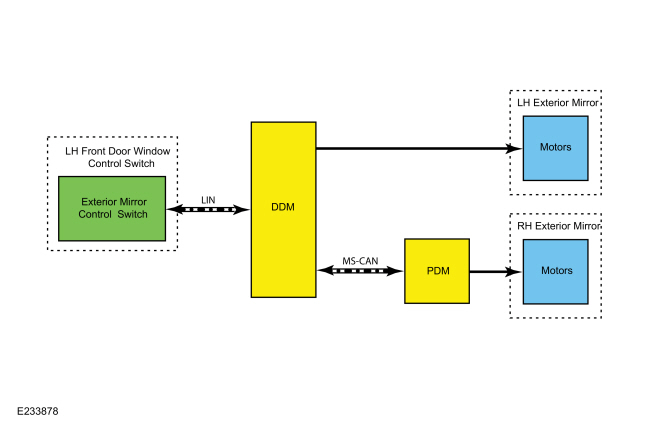
Normal Operation and Fault Conditions

The power mirror system allows the exterior mirror glass to be positioned electronically. The position of the exterior mirror glass is controlled by the exterior mirror control switch and the LH or RH mirror selection buttons determine which exterior mirror glass is controlled. If all power windows can be operated normally from the LH front door window control switch and LH and RH mirrors glass selection and positioning not possible. It indicates there is a concern with the LH front door window control switch.

Possible Sources

  • Wiring, terminals or connectors
  • Power window concern
  • Exterior mirror control switch (integral to the LH front door window control switch)
  • DDM
E1 CHECK FOR CORRECT EXTERIOR MIRROR OPERATION
  • Ignition ON.
  • Using a diagnostic scan tool, clear the Diagnostic Trouble Codes (DTCs) for the module in question.

Was an obvious cause found?
Yes VERIFY that all power windows can be operated normally from the LH front door window control switch.
If all power windows operate normally from the LH front door window control switch, INSTALL a new LH front door window control switch.
REFER to: Driver Door Window Control Switch (501-11 Glass, Frames and Mechanisms, Removal and Installation). If all power window do not operate normally from the LH front door window control switch, DIAGNOSE the power windows before continuing diagnostics for the exterior mirrors.
REFER to: Glass, Frames and Mechanisms - Vehicles With: One-Touch Open and Close Front Windows (501-11 Glass, Frames and Mechanisms, Diagnosis and Testing).
REFER to: Glass, Frames and Mechanisms - Vehicles With: One-Touch Open Driver Window (501-11 Glass, Frames and Mechanisms, Diagnosis and Testing).
No The repair is complete.

PINPOINT TEST F: THE LEFT HAND (LH) AND RIGHT HAND (RH) HEATED EXTERIOR MIRRORS DO NOT DEFROST AT THE SAME RATE

Normal Operation and Fault Conditions

The exterior mirrors are available with heated mirror glass, which heats the mirror glass to remove frost, snow, ice and condensation. The rear window defrost switch controls operation of the heated exterior mirror glass. The heated exterior mirror glass only operates when the rear window defrost system is active. If both mirrors do not defrost at same rate, it indicates there is a concern with the mirror and it's DTC's.

Possible Sources

  • Normal operation of the heated exterior mirror
F1 CHECK FOR CORRECT EXTERIOR MIRROR OPERATION
  • Ignition ON.
  • Using a diagnostic scan tool, clear the Diagnostic Trouble Codes (DTCs) for the module in question.

Was an obvious cause found?
Yes No action required, the system is operating correctly at this time.
No The repair is complete.

PINPOINT TEST G: AN EXTERIOR MIRROR SELECTION SWITCH LIGHT EMITTING DIODE (LED) IS INOPERATIVE (EXTERIOR MIRROR SELECTION SWITCH FUNCTIONS NORMALLY)

Normal Operation and Fault Conditions

LH or RH mirror selection button determine which exterior mirror glass is controlled with LED is ON at selected side. If mirror selection switch functions normally but LED is inoperative, it indicates there is a concern with LH front door window control switch.

Possible Sources

  • Exterior mirror selection switch
G1 CHECK FOR CORRECT EXTERIOR MIRROR SELECTION SWITCH OPERATION
  • Ignition ON.
  • Using a diagnostic scan tool, clear the Diagnostic Trouble Codes (DTCs) for the module in question.

Was an obvious cause found?
Yes INSTALL a new LH front door window control switch.
REFER to: Driver Door Window Control Switch (501-11 Glass, Frames and Mechanisms, Removal and Installation).
No The repair is complete.

PINPOINT TEST H: THE EXTERIOR MIRROR PUDDLE LAMP IS INOPERATIVE OR ALWAYS ON

Normal Operation and Fault Conditions

REFER to: Rear View Mirrors - System Operation and Component Description (501-09 Rear View Mirrors, Description and Operation).

Possible Sources

  • Interior lighting
H1 CHECK FOR CORRECT EXTERIOR MIRROR PUDDLE LAMP OPERATION
  • Ignition ON.
  • Using a diagnostic scan tool, clear the Diagnostic Trouble Codes (DTCs) for the module in question.

Was an obvious cause found?
Yes
REFER to: Interior Lighting (417-02 Interior Lighting, Diagnosis and Testing).
No The repair is complete.

PINPOINT TEST I: THE EXTERIOR MIRROR TURN SIGNAL IS INOPERATIVE OR ALWAYS ON

Normal Operation and Fault Conditions

The steering column multifunction switch operates the exterior mirror turn signal. If other functions working normally from multifunction switch and exterior mirror turn signal is inoperative, it indicates there is a concern with multifunction switch or exterior mirror.REFER to: Exterior Lighting - System Operation and Component Description (417-01 Exterior Lighting, Description and Operation).

Possible Sources

  • Turn signal and hazard lamps
I1 CHECK FOR CORRECT EXTERIOR MIRROR TURN SIGNAL AND HAZARD LAMPS OPERATION
  • Ignition ON.
  • Using a diagnostic scan tool, clear the Diagnostic Trouble Codes (DTCs) for the module in question.

Was an obvious cause found?
Yes
REFER to: Turn Signal and Hazard Lamps (417-01 Exterior Lighting, Diagnosis and Testing).
No The repair is complete.

PINPOINT TEST J: THE BLIND SPOT INFORMATION SYSTEM (BLIS)® INDICATOR IS INOPERATIVE OR ALWAYS ON

Normal Operation and Fault Conditions

The exterior mirror BLIS ® Light Emitting Diodes (LEDs) to alert the driver that a vehicle has been detected. The BLIS ® provides alerts when the vehicle is in forward gear and the vehicle speed is greater than 10 km/h (6 mph). If BLIS ® indicator is inoperative or always ON, it indicates there is a concern with exterior mirror or BLIS ®.REFER to: Blind Spot Information System - System Operation and Component Description (419-04 Side and Rear Vision, Description and Operation).

Possible Sources

  • Blind Spot Information System
J1 CHECK FOR CORRECT BLIND SPOT INFORMATION SYSTEM OPERATION
  • Ignition ON.
  • Using a diagnostic scan tool, clear the Diagnostic Trouble Codes (DTCs) for the module in question.

Was an obvious cause found?
Yes
REFER to: Blind Spot Information System (419-04 Side and Rear Vision, Diagnosis and Testing).
No The repair is complete.

PINPOINT TEST K: THE INTERIOR MIRROR IS BLEMISHED

Normal Operation and Fault Conditions

A interior mirror is to allow the driver to see rearward through the vehicle's rear windshield. If mirror vision not clear, it indicates there is a concern with interior mirror.

Possible Sources

  • Interior mirror glass/housing is dirty
K1 CHECK FOR THE INTERIOR MIRROR SURFACE
  • Ignition ON.
  • Using a diagnostic scan tool, clear the Diagnostic Trouble Codes (DTCs) for the module in question.

Was an obvious cause found?
Yes CLEAN the affected interior mirror surface
No The repair is complete.

PINPOINT TEST L: THE INTERIOR MIRROR VIBRATES OR IS LOOSE

Normal Operation and Fault Conditions

A interior mirror is to allow the driver to see rearward through the vehicle's rear windshield. If mirror mountings are loose it start vibrates.

Possible Sources

  • Interior mirror mounting loose
L1 CHECK FOR THE INTERIOR MIRROR MOUNTINGS
  • Ignition ON.
  • Using a diagnostic scan tool, clear the Diagnostic Trouble Codes (DTCs) for the module in question.

Was an obvious cause found?
Yes If the mirror is still on the windshield, do not remove. ATTEMPT to fully seat the mirror first. If the mirror is still loose or vibrates, REMOVE and REINSTALL the mirror. If the condition still exists, INSTALL a new interior mirror.
REFER to: Interior Rear View Mirror (501-09 Rear View Mirrors, Removal and Installation).
No The repair is complete.

PINPOINT TEST M: EXTERIOR MIRROR HOUSING VIBRATES OR IS LOOSE

Normal Operation and Fault Conditions

A exterior mirror is to allow the driver see areas behind and sides of the vehicle. When exterior mirror starts vibrates, it indicates there is a concern with exterior mirror housing and mountings.

Possible Sources

  • Exterior mirror mounting nuts loose
  • Aftermarket air deflector/stone shields
M1 CHECK FOR THE EXTERIOR MIRROR MOUNTINGS
  • Ignition ON.
  • Using a diagnostic scan tool, clear the Diagnostic Trouble Codes (DTCs) for the module in question.

Was an obvious cause found?
Yes TIGHTEN the exterior mirror mounting nuts.
REFER to: Exterior Mirror (501-09 Rear View Mirrors, Removal and Installation). If possible, REMOVE the aftermarket parts and ROAD TEST the vehicle. If the concern is no longer present, ADVISE the customer that the aftermarket components were causing the undesired vibration.
No The repair is complete.

PINPOINT TEST N: EXTERIOR MIRROR GLASS VIBRATES OR IS LOOSE

Normal Operation and Fault Conditions

A exterior mirror glass is to allow the driver see areas behind and sides of the vehicle. When exterior mirror glass starts vibrates, it indicates there is a concern with exterior mirror housing and damaged backing plate.

Possible Sources

  • Exterior mirror motor mounting screws loose
  • Exterior mirror glass loose
N1 CHECK FOR THE EXTERIOR MIRROR MOUNTINGS
  • Ignition ON.
  • Using a diagnostic scan tool, clear the Diagnostic Trouble Codes (DTCs) for the module in question.

Was an obvious cause found?
Yes PRESS the center of the exterior mirror glass up, down, left and right to make sure the exterior mirror glass is seated correctly. If the exterior mirror glass is still loose, REMOVE the exterior mirror glass. INSPECT the exterior mirror backing plate for damage. INSPECT the exterior mirror motor mounting screws and TIGHTEN if necessary. If the exterior mirror backing plate is damaged, INSTALL a new exterior mirror glass.
REFER to: Exterior Mirror (501-09 Rear View Mirrors, Removal and Installation).
No The repair is complete.

PINPOINT TEST O: WIND NOISE

Normal Operation and Fault Conditions

There should not be any gaps between the exterior mirror and the door. If foam gasket is not fitted properly and mirror mountings are loose, it creates the wind noise.

Possible Sources

  • Foam gasket between exterior mirror housing and door is misaligned or damaged
  • Exterior mirror is not correctly fitted to the door
  • Exterior mirror impact damage
O1 CHECK FOR THE EXTERIOR MIRROR MOUNTINGS
  • Ignition ON.
  • Using a diagnostic scan tool, clear the Diagnostic Trouble Codes (DTCs) for the module in question.

Was an obvious cause found?
Yes PVERIFY the gasket is in good condition. If necessary, REPOSITION the gasket between the exterior mirror housing and the door. The foam gasket is not serviceable and if it cannot be repaired, INSTALL a new exterior mirror.
REFER to: Exterior Mirror (501-09 Rear View Mirrors, Removal and Installation). VERIFY there are no gaps between the exterior mirror and the door. If necessary, LOOSEN the exterior mirror nuts and REPOSITION the exterior mirror as necessary.
REFER to: Exterior Mirror (501-09 Rear View Mirrors, Removal and Installation). INSPECT the exterior mirror to ensure that there is no damage to the housing or glass.
No The repair is complete.


    Description and Operation - Rear View Mirrors - System Operation and Component Description

    S..

    Removal and Installation - Exterior Mirror

    Special Tool(s) / General Equipment Flat Headed Screw Driver Removal NOTE: Removal steps in this procedure may contain installation details...

    Other information:

    Ford Escape 2020-2024 Owners Manual: 911 Assist


    WARNING: Unless the 911 Assist setting is set on before a crash, the system will not dial for help which could delay response time, potentially increasing the risk of serious injury or death after a crash. WARNING: Do not wait for 911 Assist to make an emergency call if you can do it yourself...

    Ford Escape 2020-2024 Service Manual: Diagnosis and Testing - Direct Current/Alternating Current (DC/AC) Inverter


    Inspection and Verification Before diagnosing or repairing the Direct Current/Alternating Current (DC/AC) Inverter system refer to the Owner's Literature and REFER to: Direct Current/Alternating Current (DC/AC) Inverter - System Operation and Component Description (414-05 Voltage Converter/Inverter, Description and Operation)...

    Categories

    Adjusting the Seatbelts During Pregnancy

    WARNING: Always ride and drive with your seatback upright and properly fasten your seatbelt. Fit the lap portion of the seatbelt snugly and low across the hips. Position the shoulder portion of the seatbelt across your chest. Pregnant women must follow this practice. See the following figure.

    Ford Escape. Adjusting the Seatbelts During Pregnancy

    read more

    Copyright © 2024 www.fordescape4.com