Ford Escape: Multifunction Electronic Modules / General Procedures - Factory Mode Deactivation
Deactivation
NOTE: During vehicle build, some modules, such as the IPC and BCM module are set in factory mode. Factory mode reduces the drain on the battery during longer periods where the vehicle is not used. While in the factory mode, various systems may be altered or disabled and the IPC displays FACTORY MODE CONTACT DEALER in the message center. If the vehicle is in factory mode, the system automatically reverts to Transport mode after 60 ignition cycles. If the IPC displays TRANSPORT MODE CONTACT DEALER, refer to the Transport Mode Deactivation procedure in this section.
-
Place the ignition in the OFF position.
-
Verify the battery is fully charged.
Refer to: Battery Charging (414-01 Battery, Mounting and Cables, General Procedures).
-
Without push button start, cycle the ignition from off to on 60 times.
-
NOTE: One IKT must be in the vehicle.
With push button start, press the Engine Start/Stop button 120 times.
-
Refer to the Transport Mode Deactivation procedure in this section.
Refer to: Transport Mode Deactivation (419-10 Multifunction Electronic Modules, General Procedures).
 Diagnosis and Testing - Body Control Module C (BCMC)
Diagnostic Trouble Code (DTC) Chart
Diagnostics in this manual assume a certain skill level and knowledge of Ford-specific diagnostic practices. REFER to: Diagnostic Methods (100-00 General Information, Description and Operation)...
 General Procedures - Transport Mode Deactivation
Deactivation
NOTE:
After vehicle build, some vehicle modules are set in Transport mode
including the IPC and the BCM . Transport mode reduces battery drain
during longer periods where the vehicle is not used...
Other information:
Ford Escape 2020-2026 Service Manual: Removal and Installation - Fuel Vapor Vent Valve - Hybrid Electric Vehicle (HEV)
Removal WARNING: Do not smoke, carry lighted tobacco or have an open flame of any type when working on or near any fuel-related component. Highly flammable mixtures may be present and may be ignited. Failure to follow these instructions may result in serious personal injury...
Ford Escape 2020-2026 Owners Manual: Emergency Towing
Hybrid Electric Vehicle (HEV)/Plug-In Hybrid Electric Vehicle (PHEV) If your vehicle becomes inoperable without access to wheel dollies or a vehicle transport trailer, it can be flat-towed with all wheels on the ground, regardless of the powertrain and transmission configuration, under the following conditions: Your vehicle is facing forward for towing in a forward direction...
Categories
- Manuals Home
- 4th Generation Ford Escape Owners Manual
- 4th Generation Ford Escape Service Manual
- Switching the Rear Window Wiper On and Off. Reverse Wipe
- Description and Operation - Identification Codes
- Plug-In Hybrid Electric Vehicle Drive Modes
- New on site
- Most important about car
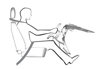
Sitting in the Correct Position

When you use them properly, the seat, head restraint, seatbelt and airbags will provide optimum protection in the event of a crash.
