Ford Escape: Accessory Drive - 1.5L EcoBoost (132kW/180PS) – I3 (Y1) / Removal and Installation - Accessory Drive Belt - Vehicles Built Up To: 1-October-2020
Special Tool(s) / General Equipment
| 5 mm Drill Bit |
Removal
NOTE: Removal steps in this procedure may contain installation details.
-
Refer to: Health and Safety Precautions (100-00 General Information, Description and Operation).
-
Refer to: Jacking and Lifting - Overview (100-02 Jacking and Lifting, Description and Operation).
- Torque: 13 lb.in (1.5 Nm)
.jpg) |
- Torque: 119 lb.in (13.5 Nm)
 |
-
.jpg) WARNING:
The tensioner is under spring tension. Be careful
when handling the tensioner. Failure to follow this instruction may
result in personal injury.
WARNING:
The tensioner is under spring tension. Be careful
when handling the tensioner. Failure to follow this instruction may
result in personal injury.
-
Using the 15mm lug nut feature on the the accessory
drive belt tensioner, rotate the accessory drive belt tensioner counter
clockwise.
- Use the General Equipment: 5 mm Drill Bit
-
Remove the accessory drive belt from the accessory
drive belt tensioner pulley. Release the accessory drive belt tensioner
and remove the accessory drive belt.
-
Using the 15mm lug nut feature on the the accessory
drive belt tensioner, rotate the accessory drive belt tensioner counter
clockwise.
 |
Installation
-
.jpg) WARNING:
The tensioner is under spring tension. Be careful
when handling the tensioner. Failure to follow this instruction may
result in personal injury.
WARNING:
The tensioner is under spring tension. Be careful
when handling the tensioner. Failure to follow this instruction may
result in personal injury.
-
Install the accessory drive belt onto the pulleys
starting at the accessory drive belt tensioner pulley and then securely
install the belt in the generator pulley, the A/C Compressor pulley,
crankshaft pulley and the water pump pulley.
-
Using the 15mm lug nut feature on the the accessory
drive belt tensioner, rotate the accessory drive belt tensioner.
-
Release the tensioner.
-
Install the accessory drive belt onto the pulleys
starting at the accessory drive belt tensioner pulley and then securely
install the belt in the generator pulley, the A/C Compressor pulley,
crankshaft pulley and the water pump pulley.
 |
-
To install, reverse the removal procedure.
-
NOTICE: Only rotate the crankshaft clockwise.
NOTICE: Make sure that the accessory drive belt is correctly located on each pulley.
.jpg) |
 Removal and Installation - Accessory Drive Belt Idler Pulley
Removal
Refer to: Accessory Drive Belt - Vehicles Built Up To: 1-October-2020
(303-05A Accessory Drive - 1.5L EcoBoost (132kW/180PS) – I3 (Y1),
Removal and Installation)...
Other information:
Ford Escape 2020-2024 Service Manual: Removal and Installation - Condenser Outlet Line - 1.5L EcoBoost (132kW/180PS) – I3 (Y1)
Removal NOTICE: During the removal of components, cap, tape or otherwise appropriately protect all openings to prevent the ingress of dirt or other contamination. Remove protective materials prior to installation. NOTE: Removal steps in this procedure may contain installation details...
Ford Escape 2020-2024 Service Manual: Removal and Installation - Hood Latch
Removal NOTE: Removal steps in this procedure may contain installation details. Remove the air cleaner inlet pipe. Refer to: Air Cleaner Intake Pipe (303-12C Intake Air Distribution and Filtering, Removal and Installation). Refer to: Air Cleaner Intake Pipe (303-12A Intake Air Distribution and Filtering - 1...
Categories
- Manuals Home
- 4th Generation Ford Escape Owners Manual
- 4th Generation Ford Escape Service Manual
- Rear View Camera
- Power Outlet - Vehicles With: 12V Power Outlet
- General Procedures - Transmission Fluid Level Check
- New on site
- Most important about car
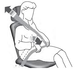
Adjusting the Seatbelts During Pregnancy
WARNING: Always ride and drive with your seatback upright and properly fasten your seatbelt. Fit the lap portion of the seatbelt snugly and low across the hips. Position the shoulder portion of the seatbelt across your chest. Pregnant women must follow this practice. See the following figure.


