Ford Escape: Engine Cooling / Removal and Installation - Cooling Module
Special Tool(s) /
General Equipment
| Hose Clamp Remover/Installer |
| Interior Trim Remover |
Removal
NOTICE:
When removing any turbocharger air intake system components,
make sure to cover any open ports to prevent debris from entering the
system. The turbocharger compressor vanes can be damaged by even the
smallest particles. All components need to be inspected and cleaned
prior to installation or reassembly.
NOTE:
Removal steps in this procedure may contain installation details.
-
Remove the air cleaner assembly.
Refer to: Air Cleaner (303-12C Intake Air Distribution and Filtering, Removal and Installation).
-
Drain the cooling system.
Refer to: Engine Cooling System Draining, Vacuum Filling and Bleeding (303-03C Engine Cooling, General Procedures).
-
Drain the electric powertrain cooling system.
Refer to: Cooling System Filling and Bleeding (303-03D Electric
Powertrain Cooling - Hybrid Electric Vehicle (HEV), General Procedures).
-
Recover the A/C system.
Refer to: Air Conditioning (A/C) System Recovery, Evacuation and
Charging - 2.5L Duratec – Hybrid (121kW/164PS) (BG) (412-00 Climate
Control System - General Information, General Procedures).
Refer to: Air Conditioning (A/C) System Recovery,
Evacuation and Charging - Hybrid Electric Vehicle (HEV), Vehicles With:
R134A Refrigerant (412-00 Climate Control System - General Information -
2.5L Duratec – Hybrid (121kW/164PS) (BG))
.
-
Remove the front bumper cover.
Refer to: Front Bumper Cover (501-19 Bumpers, Removal and Installation).
-
Remove the headlamp assemblies.
Refer to: Headlamp Assembly (417-01 Exterior Lighting, Removal and Installation).
-
-
Release the clips, tabs and remove the radiator air deflectors.
Use the General Equipment: Interior Trim Remover
-
If equipped.
Remove the CCM .
-
Remove the air cleaner intake pipe.
Refer to: Air Cleaner Intake Pipe (303-12C Intake Air Distribution and Filtering, Removal and Installation).
-
-
Disconnect the electrical connector.
-
Detach the latch cable retainers.
-
Remove the bolts and position the latch assembly aside.
Torque:
93 lb.in (10.5 Nm)
-
NOTE:
Support the hood before removing the hood support rod.
Remove the hood support rod.
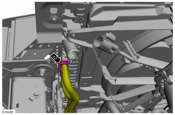
-
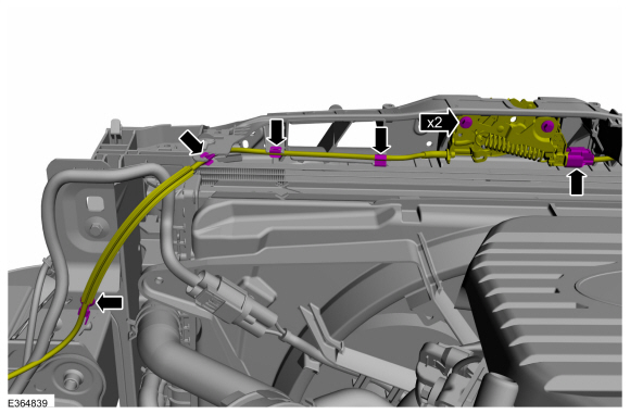
Disconnect the cooling fan and shroud electrical connector and detach the wiring harness retainers.
-
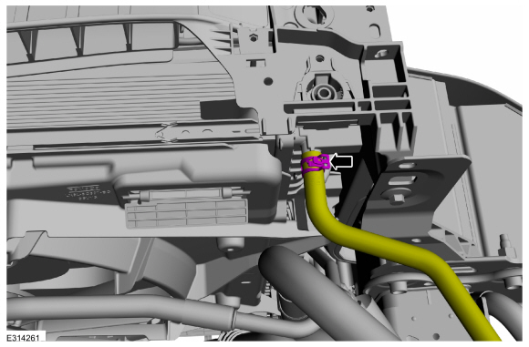
Detach the transmission oil cooler hoses retainer.
-
If equipped.
Detach the wiring harness retainers.
-
NOTE:
All components are not shown for clarity.
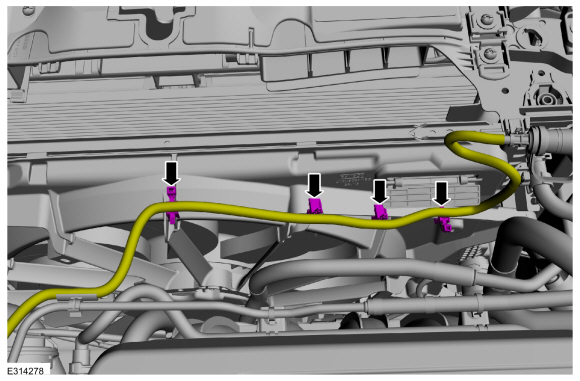
Detach the wiring harness retainers.
-
Remove the bolts and detach the auxiliary radiator coolant hose.
Torque:
36 lb.in (4.1 Nm)
-
Release the clamp and disconnect the upper radiator hose.
Use the General Equipment: Hose Clamp Remover/Installer
-
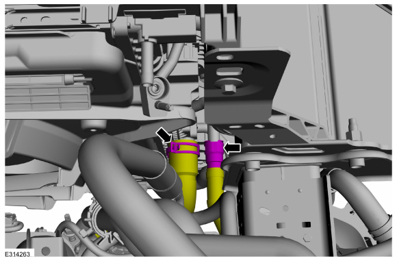
Release the clamps and disconnect the transmission oil cooler hoses.
Use the General Equipment: Hose Clamp Remover/Installer
-
Release the clamp and disconnect the radiator vent hose.
Use the General Equipment: Hose Clamp Remover/Installer
-
NOTICE:
Make sure that all openings are sealed.
-
Remove the nut and disconnect the condenser inlet fitting.
Torque:
159 lb.in (18 Nm)
-
Remove the nut and disconnect the condenser outlet fitting.
Torque:
80 lb.in (9 Nm)
-
Disconnect the quick connect hose couplings.
-
-
Release the clamp and disconnect the coolant hose.
Use the General Equipment: Hose Clamp Remover/Installer
-
Disconnect the quick connect hose coupling.
-
Disconnect the quick connect hose coupling.
-
Disconnect the electrical connector.
-
Detach the A/C pressure switch wiring harness retainer.
-
Disconnect the horn electrical connector and detach the wiring harness retainer.
-
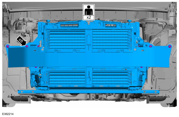
Remove the bottom cooling module support bar bolts.
Torque:
22 lb.ft (30 Nm)
-
On both side.
Remove the bolt.
Torque:
46 lb.ft (63 Nm)
-
NOTE:
This step requires the aid of another technician.
Remove the nuts and the cooling module assembly.
Torque:
46 lb.ft (63 Nm)
-
Remove the cooling module assembly bolts and the bumper reinforcement.
Torque:
93 lb.in (10.5 Nm)
Installation
-
To install, reverse the removal procedure.
-
Install and lubricate new condenser fitting O-ring seals.
Refer to: Specifications (412-00 Climate Control System - General Information, Specifications).
-
Evacuate, leak test and charge the A/C system.
Refer to: Air Conditioning (A/C) System Recovery, Evacuation and
Charging - 2.5L Duratec – Hybrid (121kW/164PS) (BG) (412-00 Climate
Control System - General Information, General Procedures).
Refer to: Air Conditioning (A/C) System Recovery,
Evacuation and Charging - Hybrid Electric Vehicle (HEV), Vehicles With:
R134A Refrigerant (412-00 Climate Control System - General Information -
2.5L Duratec – Hybrid (121kW/164PS) (BG))
.
-
Fill and bleed the cooling system.
Refer to: Engine Cooling System Draining, Vacuum Filling and Bleeding (303-03C Engine Cooling, General Procedures).
-
Fill and bleed the electric powertrain cooling system.
Refer to: Cooling System Filling and Bleeding (303-03D Electric
Powertrain Cooling - Hybrid Electric Vehicle (HEV), General Procedures).
-
Check and fill the transmission fluid as necessary.
Refer to: Transmission Fluid Level Check (307-01B Automatic Transmission - Automatic Transmission – HF45, General Procedures).
Removal
NOTE:
Removal steps in this procedure may contain installation details.
With the vehicle in NEUTRAL, position it on a hoist.
Refer to: Jacking and Lifting - Overview (100-02 Jacking and Lifting, Description and Operation)...
Special Tool(s) /
General Equipment
Fluid Suction Gun
Hose Clamp Remover/Installer
Locking Pliers
Removal
WARNING:
Always allow the engine to cool before opening the cooling
system...
Other information:
System Operation
System Diagram
Item
Description
1
Intake manifold
2
EVAP canister purge valve
3
Fresh air hose
4
EVAP leak detection pump
5
EVAP canister
6
Fuel tank
7
Fuel pump and sender unit
8
Fuel tank isolation valve (also known as Tank Pressure Control Valve - TPC )
..
Press the control button to unlatch the
liftgate and then lift to open.
Note: Be careful when opening or closing
the liftgate in a garage or other enclosed
area to avoid damaging the liftgate.
Note: Do not hang anything, for example a
bike rack, from the glass or liftgate. This
could damage the liftgate and its
components.
Note: Do not leave the liftgate open while
driving. This could dama..
.jpg)
.jpg)
.jpg)
.jpg)
.jpg)

.jpg)
.jpg)
.jpg)
.jpg)
.jpg)
.jpg)
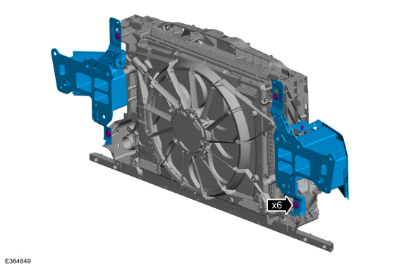
 Removal and Installation - Cooling Fan Motor and Shroud
 Removal and Installation - Degas Bottle