Ford Escape 2020-2026 Service Manual / Powertrain / Engine / Engine Cooling / Removal and Installation - Cooling Fan Motor and Shroud
Ford Escape: Engine Cooling / Removal and Installation - Cooling Fan Motor and Shroud
Removal
NOTE: Removal steps in this procedure may contain installation details.
-
With the vehicle in NEUTRAL, position it on a hoist.
Refer to: Jacking and Lifting - Overview (100-02 Jacking and Lifting, Description and Operation).
-
Remove the retainers, release the tabs and remove the air cleaner intake duct pipe.
.jpg) |
-
Disconnect the cooling fan electrical connector.
.jpg) |
-
Detach the transmission oil cooler hoses retainer.
.jpg) |
-
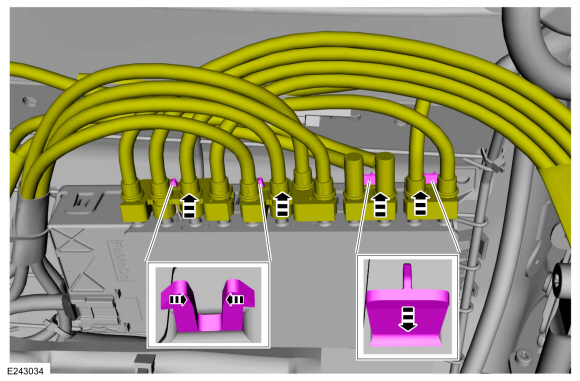
Detach the wiring harness retainers.
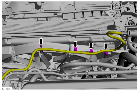 |
-
NOTE: All components are not shown for clarity.
Detach the wiring harness retainers.
 |
-
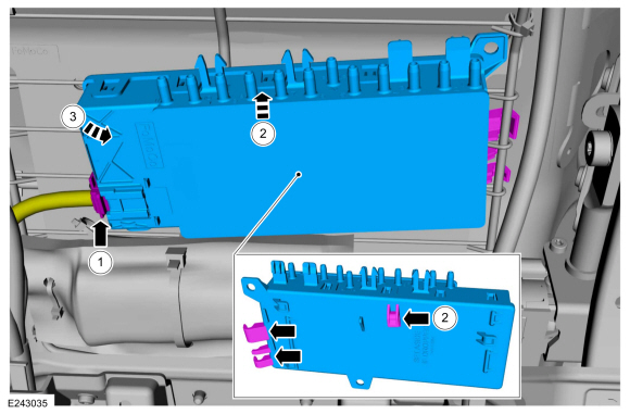
Remove the retainers and detach the auxiliary radiator coolant hose.
Torque: 36 lb.in (4.1 Nm)
.jpg) |
-
Remove the bolts, release the tabs and remove the cooling fan motor and shroud.
Torque: 71 lb.in (8 Nm)
 |
Installation
-
To install, reverse the removal procedure.
 Removal and Installation - Coolant Pump
Special Tool(s) /
General Equipment
Hose Clamp Remover/Installer
Removal
Drain the cooling system.
Refer to: Engine Cooling System Draining, Vacuum Filling and Bleeding (303-03C Engine Cooling, General Procedures)...
 Removal and Installation - Cooling Module
Special Tool(s) /
General Equipment
Hose Clamp Remover/Installer
Interior Trim Remover
Removal
NOTICE:
When removing any turbocharger air intake system components,
make sure to cover any open ports to prevent debris from entering the
system...
Other information:
Ford Escape 2020-2026 Service Manual: Removal and Installation - Rear Seat Backrest Cover
Special Tool(s) / General Equipment Interior Trim Remover Hog Ring Plier Removal WARNING: Seat backrest trim covers installed on seats equipped with seat side airbags cannot be repaired. A new trim cover must be installed...
Ford Escape 2020-2026 Owners Manual: Jump Starting the Vehicle
Jump Starting Precautions WARNING: Batteries normally produce explosive gases which can cause personal injury. Therefore, do not allow flames, sparks or lighted substances to come near the battery. When working near the battery, always shield your face and protect your eyes...
Categories
- Manuals Home
- 4th Generation Ford Escape Owners Manual
- 4th Generation Ford Escape Service Manual
- All-Wheel Drive
- Description and Operation - Identification Codes
- Child Safety Locks
- New on site
- Most important about car
Fastening the Seatbelts

Copyright © 2026 www.fordescape4.com