Ford Escape 2020-2026 Service Manual / Electrical / Electronic Feature Group / Multifunction Electronic Modules / Removal and Installation - Driver Door Module (DDM)
Ford Escape: Multifunction Electronic Modules / Removal and Installation - Driver Door Module (DDM)
Removal
NOTE: Removal steps in this procedure may contain installation details.
-
NOTE: If installing a new module, it is necessary to upload the module configuration information to the diagnostic scan tool prior to removing the module. This information must be downloaded into the new module after installation.
Carry out the PMI procedure for the DDM .
Refer to: Module Configuration - System Operation and Component Description (418-01 Module Configuration, Description and Operation).
-
Remove the front door trim panel.
Refer to: Front Door Trim Panel (501-05 Interior Trim and Ornamentation, Removal and Installation).
-
Remove the bolts and the DDM .
-
Disconnect the electrical connectors.
-
Disconnect the electrical connectors.
.jpg) |
Installation
-
To install, reverse the removal procedure.
-
Using the previous diagnostic scan tool session, carry out the PMI procedure for the DDM .
Refer to: Module Configuration - System Operation and Component Description (418-01 Module Configuration, Description and Operation).
-
If installing a new module, carry out the power door
window initialization on the drivers side front and rear door windows.
Refer to: Power Door Window Initialization - Vehicles With: One-Touch Open and Close Front Windows (501-11 Glass, Frames and Mechanisms, General Procedures).
 Removal and Installation - Body Control Module C (BCMC)
Removal
NOTE:
Removal steps in this procedure may contain installation details.
NOTE:
If the BCMC (body control module C) did not respond
to the diagnostic scan tool, As-Built Data may need to be entered as
part of the repair...
 Removal and Installation - Passenger Door Module (PDM)
Removal
NOTE:
Removal steps in this procedure may contain installation details.
NOTE:
Drivers side shown, passenger side similar.
NOTE:
If installing a new module, it is necessary to
upload the module configuration information to the diagnostic scan tool
prior to removing the module...
Other information:
Ford Escape 2020-2026 Owners Manual: Cleaning the Interior
Cleaning the Instrument Panel WARNING: Do not use chemical solvents or strong detergents when cleaning the steering wheel or instrument panel to avoid contamination of the airbag system. We recommend that you only clean the instrument panel and cluster lens with a damp soft cloth...
Ford Escape 2020-2026 Service Manual: Removal and Installation - Roof Panel
Special Tool(s) / General Equipment Resistance Spotwelding Equipment Knife 8 mm Drill Bit MIG/MAG Welding Equipment Spot Weld Drill Bit Locking Pliers Materials Name Specification Metal Bonding AdhesiveTA-1, TA-1-B, 3M™ 08115, LORD Fusor® 108B, Henkel Teroson EP 5055 - Seam SealerTA-2-B, 3M™ 08308, LORD Fusor® 803DTM - R..
Categories
- Manuals Home
- 4th Generation Ford Escape Owners Manual
- 4th Generation Ford Escape Service Manual
- Drive Modes
- Description and Operation - Identification Codes
- All-Wheel Drive
- New on site
- Most important about car
Vehicle Identification
Locating the Vehicle Identification Number
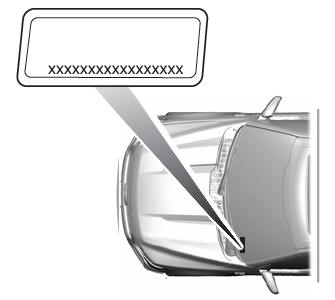
The vehicle identification number is on the left-hand side of the instrument panel.

Copyright © 2026 www.fordescape4.com
