
Ford Escape 2020-2024 Service Manual / Body and Paint / Body and Paint / Handles, Locks, Latches and Entry Systems / Removal and Installation - Exterior Front Door Handle Reinforcement
Ford Escape: Handles, Locks, Latches and Entry Systems / Removal and Installation - Exterior Front Door Handle Reinforcement
Removal
NOTE: LH (left-hand) side shown, RH (right-hand) side similar.
-
Remove the front door latch.
Refer to: Front Door Latch (501-14 Handles, Locks, Latches and Entry Systems, Removal and Installation).
-
NOTE: This step is only necessary when installing a new component.
NOTE: Follow the unique instructions or graphic for this step in installation.
Release the cable tension by turning the release screw until the handle lever releases from the stop.
-
Turn the release screw until the handle lever releases from the stop.
-
Release the handle lever from the stop.
-
Turn the release screw until the handle lever releases from the stop.
.jpg) |
-
NOTE: This step is only necessary when installing a new component.
Remove the exterior front door handle reinforcement.
-
Detach the cable from the exterior front door handle reinforcement cable bracket.
-
Remove the cable eyelet from the lever.
-
Press the locking tab down.
-
If equipped, disconnect the door lock cylinder rod.
Remove the exterior front door handle reinforcement.
-
Detach the cable from the exterior front door handle reinforcement cable bracket.
.jpg) |
Installation
-
To install, reverse the removal procedure.
-
NOTE: This step is only necessary when installing a new component.
NOTE: This step must be done correctly or the exterior door handle will not engage the lever on installation.
Position the exterior front door handle reinforcement in the service position.
-
While keeping tension on the cable and holding the handle lever in the engaged position against the stop.
-
Turn the release screw until the handle lever is positioned against the stop.
-
While keeping tension on the cable and holding the handle lever in the engaged position against the stop.
.jpg) |
-
If the door is equipped with one touch up/down, carry out the power
door window initialization.
Refer to: Power Door Window Initialization - Vehicles With: One-Touch
Open and Close Front Windows (501-11 Glass, Frames and Mechanisms,
General Procedures).
 Removal and Installation - Exterior Front Door Handle
Removal
NOTE:
LH (left-hand) side shown, RH (right-hand) side similar.
NOTE:
Removal steps in this procedure may contain installation details.
Vehicles with passive entry
Remove the front door window regulator and motor...
 Removal and Installation - Exterior Rear Door Handle
Removal
NOTE:
LH (left-hand) side shown, RH (right-hand) side similar.
NOTE:
Removal steps in this procedure may contain installation details.
Remove the exterior rear door handle access plug...
Other information:
Ford Escape 2020-2024 Owners Manual: Brakes – Troubleshooting
Brakes – Warning Lamps If the ABS indicator illuminates when you are driving, this indicates a malfunction. Your vehicle continues to have normal braking without the anti-lock braking system function. See an authorized dealer. It also momentarily illuminates when you switch the ignition on to confirm the lamp is functional...
Ford Escape 2020-2024 Service Manual: Diagnosis and Testing - Parking Brake
Diagnostic Trouble Code (DTC) Chart Diagnostics in this manual assume a certain skill level and knowledge of Ford-specific diagnostic practices. REFER to: Diagnostic Methods (100-00 General Information, Description and Operation). Diagnostic Trouble Code Chart Module DTC Description Action ABS B1111..
Categories
- Manuals Home
- 4th Generation Ford Escape Owners Manual
- 4th Generation Ford Escape Service Manual
- General Procedures - Brake Service Mode Activation and Deactivation
- Accessing the Trip Computer. Resetting the Trip Computer
- Switching the Lane Keeping System On and Off. Switching the Lane Keeping System Mode. Alert Mode
- New on site
- Most important about car
Vehicle Identification
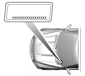
Locating the Vehicle Identification Number
The vehicle identification number is on the left-hand side of the instrument panel.

Copyright © 2024 www.fordescape4.com