Ford Escape: Handles, Locks, Latches and Entry Systems / Removal and Installation - Front Door Latch
Removal
NOTE: LH (left-hand) side shown, RH (right-hand) side similar.
NOTE: Removal steps in this procedure may contain installation details.
-
Remove the front door window regulator and motor.
Refer to: Front Door Window Regulator and Motor (501-11 Glass, Frames and Mechanisms, Removal and Installation).
-
Remove the exterior front door handle.
Refer to: Exterior Front Door Handle (501-14 Handles, Locks, Latches and Entry Systems, Removal and Installation).
-
If equipped.
Remove the door lock cylinder.
Refer to: Door Lock Cylinder (501-14 Handles, Locks, Latches and Entry Systems, Removal and Installation).
-
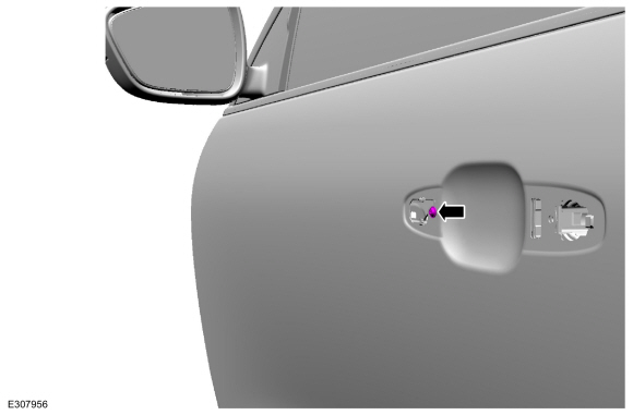
Remove the screw from the exterior front door handle reinforcement.
Torque: 19 lb.in (2.2 Nm)
 |
-
Remove the front door glass run and bracket bolts.
Torque: 17 lb.in (1.9 Nm)
.jpg) |
-
Remove the front door latch bolts.
Torque: 71 lb.in (8 Nm)
.jpg) |
-
Remove the front door latch.
-
If equipped.
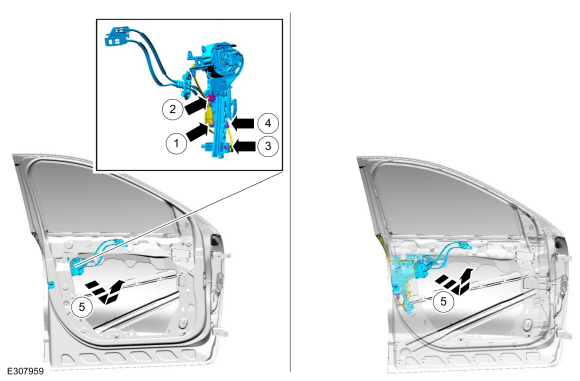
Disconnect the keyless entry keypad electrical connector.
-
Disconnect the front door latch electrical connector.
-
Disconnect the front door latch jumper harness routing clip.
-
Disconnect the front door latch jumper harness electrical connector.
-
Remove the front door latch.
-
If equipped.
 |
-
NOTE: This step is only necessary when installing a new component.
NOTE: Follow the unique instructions or graphic for this step in installation.
Release the cable tension by turning the release screw until the handle lever releases from the stop.
-
Turn the release screw until the handle lever releases from the stop.
-
Release the handle lever from the stop.
-
Turn the release screw until the handle lever releases from the stop.
.jpg) |
-
NOTE: This step is only necessary when installing a new component.
Remove the exterior front door handle reinforcement.
-
Detach the cable from the exterior front door handle reinforcement cable bracket.
-
Remove the cable eyelet from the lever.
-
Press the locking tab down.
-
If equipped, disconnect the door lock cylinder rod.
Remove the exterior front door handle reinforcement.
-
Detach the cable from the exterior front door handle reinforcement cable bracket.
.jpg) |
-
NOTE: This step is only necessary when installing a new component.
Remove the front door glass run and bracket.
-
Release the front door glass run and bracket retaining tab.
-
Release the front door glass run and bracket retaining tab.
-
Remove the front door glass run and bracket from the front door latch.
-
Release the front door glass run and bracket retaining tab.
.jpg) |
-
NOTE: This step is only necessary when installing a new component.
Remove the front door latch lock rod.
.jpg) |
-
NOTE: This step is only necessary when installing a new component.
Remove the exterior front door handle reinforcement to front door latch cable access cover.
.jpg) |
-
NOTE: This step is only necessary when installing a new component.
Remove the exterior front door handle reinforcement to front door latch cable.
-
Remove the exterior front door handle reinforcement to front door latch cable front the mounting bracket.
-
Remove the exterior front door handle reinforcement to front door latch cable end from the front door latch.
-
Remove the exterior front door handle reinforcement to front door latch cable front the mounting bracket.
.jpg) |
-
NOTE: This step is only necessary when installing a new component.
Remove the interior front door handle cable and lock indicator cable access covers.
-
Remove the lock indicator cable access cover.
-
Remove the interior front door handle cable access cover.
-
Remove the lock indicator cable access cover.
.jpg) |
-
NOTE: This step is only necessary when installing a new component.
Remove the interior front door handle cable and lock indicator cable.
-
Remove the lock indicator cable from the mounting bracket.
-
Remove the lock indicator cable end from the front door latch.
-
Remove the interior front door handle cable from the mounting bracket.
-
Remove the interior front door handle cable end from the front door latch.
-
Remove the lock indicator cable from the mounting bracket.
.jpg) |
Installation
-
To install, reverse the removal procedure.
-
NOTE: This step is only necessary when installing a new component.
NOTE: This step must be done correctly or the exterior door handle will not engage the lever on installation.
Position the exterior front door handle reinforcement in the service position.
-
While keeping tension on the cable and holding the handle lever in the engaged position against the stop.
-
Turn the release screw until the handle lever is positioned against the stop.
-
While keeping tension on the cable and holding the handle lever in the engaged position against the stop.
.jpg) |
-
If the door is equipped with one touch up/down, carry out the power
door window initialization.
Refer to: Power Door Window Initialization - Vehicles With: One-Touch
Open and Close Front Windows (501-11 Glass, Frames and Mechanisms,
General Procedures).
 Removal and Installation - Exterior Rear Door Handle Reinforcement
Removal
NOTE:
LH (left-hand) side shown, RH (right-hand) side similar.
Remove the rear door latch.
Refer to: Rear Door Latch (501-14 Handles, Locks, Latches and Entry Systems, Removal and Installation)...
 Removal and Installation - Front Door Lock Control Switch
Removal
NOTE:
LH (left-hand) side shown, RH (right-hand) side similar.
Remove the front door trim panel.
Refer to: Front Door Trim Panel (501-05 Interior Trim and Ornamentation, Removal and Installation)...
Other information:
Ford Escape 2020-2026 Service Manual: General Procedures - Vent Patch
Repair WARNING: To prevent the risk of high-voltage shock, always follow precisely all warnings and service instructions, including instructions to depower the system. The high-voltage system utilizes approximately 450 volts DC, provided through high-voltage cables to its components and modules...
Ford Escape 2020-2026 Service Manual: Description and Operation - Direct Current/Alternating Current (DC/AC) Inverter - System Operation and Component Description
System Diagram System Operation Network Message Chart Broadcast Message Originating Module Message Purpose Power pack torque status Secondary On-Board Diagnostic Control Module C (SOBDMC) Used to determine if the vehicle is started or if torque is available...
Categories
- Manuals Home
- 4th Generation Ford Escape Owners Manual
- 4th Generation Ford Escape Service Manual
- Power Outlet - Vehicles With: 12V Power Outlet
- Drive Modes
- Child Safety Locks
- New on site
- Most important about car
Fastening the Seatbelts