Ford Escape: Engine / Removal and Installation - Intake Manifold
Removal
-
With the vehicle in NEUTRAL, position it on a hoist.
Refer to: Jacking and Lifting - Overview (100-02 Jacking and Lifting, Description and Operation).
-
Remove the fasteners and undershield.
-
Remove the nut, release the engine appearance cover from the ball-studs, then remove the cover.
-
Remove the air cleaner outlet pipe.
Refer to: Air Cleaner Outlet Pipe (303-12C Intake Air Distribution and Filtering, Removal and Installation).
-
Disconnect the hoses and the EGR cooler electrical connector.
-
Remove the bolts and position the EGR outlet tube.
-
Discard the EGR outlet tube gasket.
-
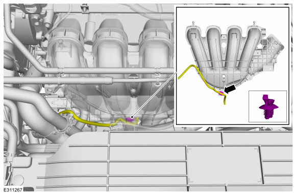
Remove the wire harness pin-type retainer.
-
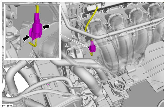
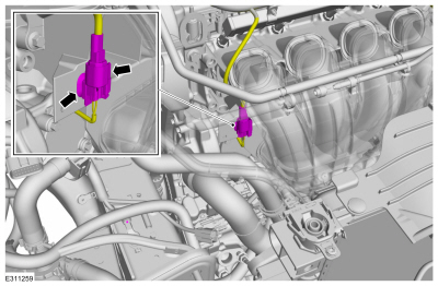
Remove the pin-type retainer and disconnect the KS .
-
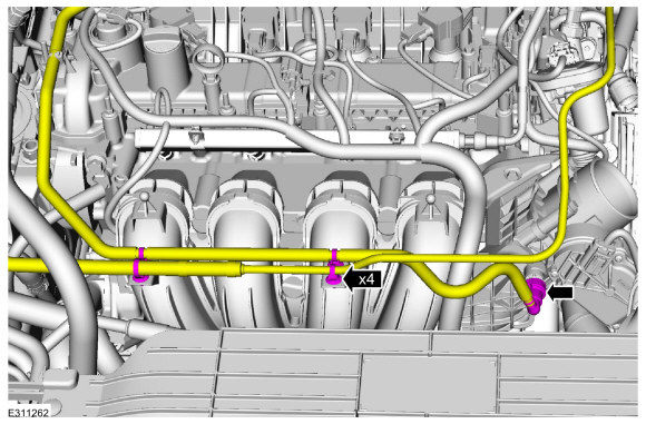
Disconnect the fuel vapor tube and remove the pin-type retainers.
Refer to: Quick Release Coupling (310-00 Fuel System -
General Information - 2.5L Duratec – Hybrid (121kW/164PS) (BG))
.
-
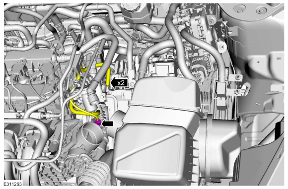
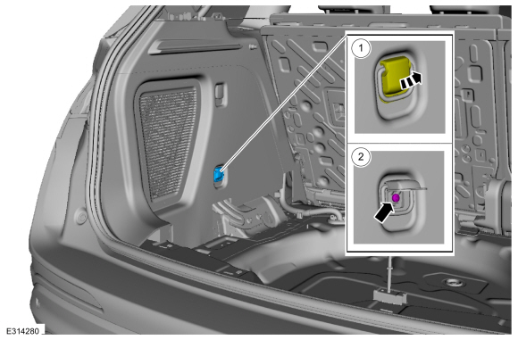
Disconnect the MAP sensor electrical connector.
-
Disconnect the throttle body electrical connector and remove the pin-type.
-
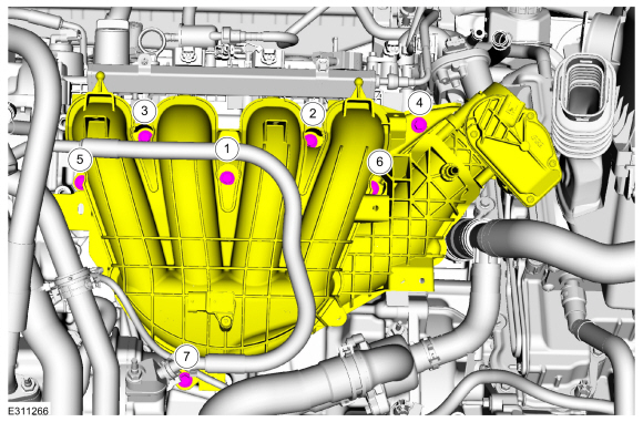
Remove the bolts and position out the intake manifold.
-
Disconnect the crankcase vent oil separator tube and remove the intake manifold.
Refer to: Quick Release Coupling (310-00 Fuel System -
General Information - 2.5L Duratec – Hybrid (121kW/164PS) (BG))
.
Installation
-
NOTE:
If the engine is repaired or replaced because of
upper engine failure, typically including valve or piston damage, check
the intake manifold for metal debris. If metal debris is found, install a
new intake manifold. Failure to follow these instructions can result in
engine damage.
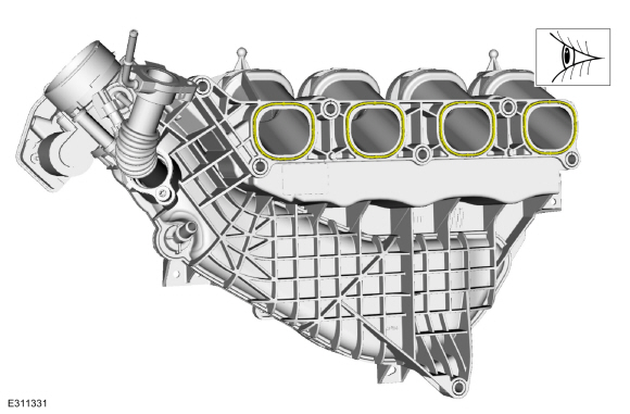
NOTE:
Visually inspect the intake manifold gaskets for
nicks, cuts and abrasions. If these conditions are not present, the
gaskets may be re-used.
-
Connect the crankcase vent oil separator tube and position back the intake manifold.
-
Install the intake manifold bolts and tighten in sequence shown.
Torque:
159 lb.in (18 Nm)
-
Connect the throttle body electrical connector and the pin-type retainers.
-
Connect the MAP sensor electrical connector.
-
Connect the fuel vapor tube and install the pin-type retainers.
Refer to: Quick Release Coupling (310-00 Fuel System -
General Information - 2.5L Duratec – Hybrid (121kW/164PS) (BG))
.
-
Install the pin-type retainer and connect the KS .
-
Install the wire harness pin-type retainer.
-
Install a new EGR outlet tube gasket.
-
Position back the EGR outlet tube and install the bolts.
Torque:
89 lb.in (10 Nm)
-
Install the hoses and connect the EGR cooler electrical connector.
-
Install the air cleaner outlet pipe.
Refer to: Air Cleaner Outlet Pipe (303-12C Intake Air Distribution and Filtering, Removal and Installation).
-
Install the engine appearance cover to the ball-studs, then install and tighten the nut.
Torque:
97 lb.in (11 Nm)
-
Install the undershield.
Removal
Remove the transmission.
Refer to: Transmission (307-01B Automatic Transmission - Automatic Transmission – HF45, Removal and Installation)...
Special Tool(s) /
General Equipment
Plastic Scraper
Oil Drain Equipment
Materials
Name
Specification
Motorcraft® High Performance Engine RTV SiliconeTA-357
WSE-M4G323-A6
Removal
Refer to: Jacking and Lifting - Overview (100-02 Jacking and Lifting, Description and Operation)...
Other information:
General Equipment
Diagnostic Battery Charger
Use Ford approved battery test equipment listed in the Ford Warranty and Policy Manual.
Diagnostics in this manual assume a certain skill level and knowledge of Ford-specific diagnostic practices...
Removal
NOTE:
Removal steps in this procedure may contain installation details.
Remove the wheel and tire.
Refer to: Wheel and Tire (204-04A Wheels and Tires, Removal and Installation).
Remove the bolts.
Torque:
13 lb...
.jpg)
.jpg)
.jpg)
.jpg)
.jpg)
.jpg)
 Removal and Installation - Flywheel
 Removal and Installation - Oil Pan