Ford Escape: Engine / Removal and Installation - Oil Pan
Special Tool(s) /
General Equipment
| Plastic Scraper |
| Oil Drain Equipment |
Materials
| Name |
Specification |
Motorcraft® High Performance Engine RTV Silicone
TA-357 |
WSE-M4G323-A6
|
Removal
-
Refer to: Jacking and Lifting - Overview (100-02 Jacking and Lifting, Description and Operation).
-
Remove the cowl panel grille.
Refer to: Cowl Panel Grille (501-02 Front End Body Panels, Removal and Installation).
LHD FWD/RHD FWD
-
Refer to: Catalytic Converter (309-00C Exhaust System, Removal and Installation).
LHD AWD/RHD AWD
-
Refer to: Catalytic Converter (309-00C Exhaust System, Removal and Installation).
All vehicles
-
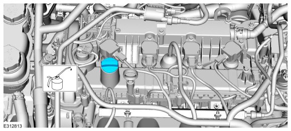
Remove the oil level indicator.
-
-
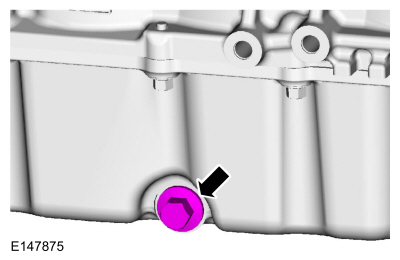
Remove the oil drain bolt and drain the engine oil.
Use the General Equipment: Oil Drain Equipment
-
Install the oil drain bolt.
Torque:
21 lb.ft (28 Nm)
-
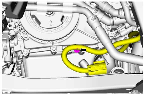
Remove the coolant pump.
Refer to: Coolant Pump (303-03C Engine Cooling, Removal and Installation).
-
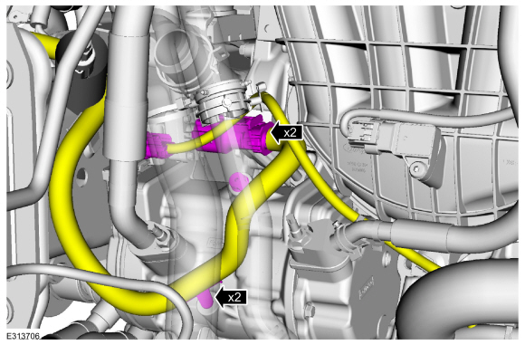
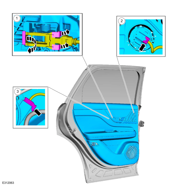
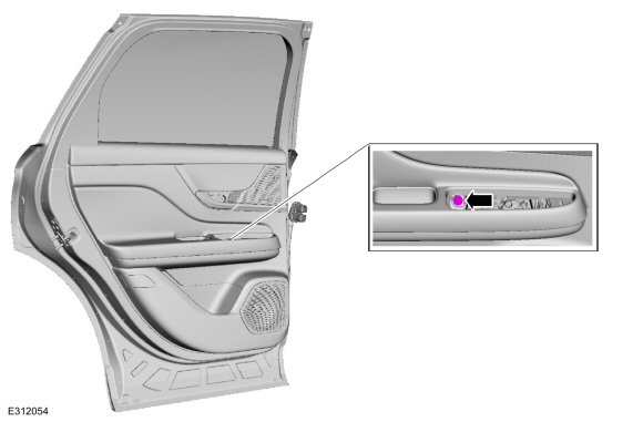
Disconnect the A/C compressor electrical connectors and pin-type retainers.
-
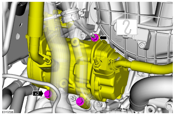
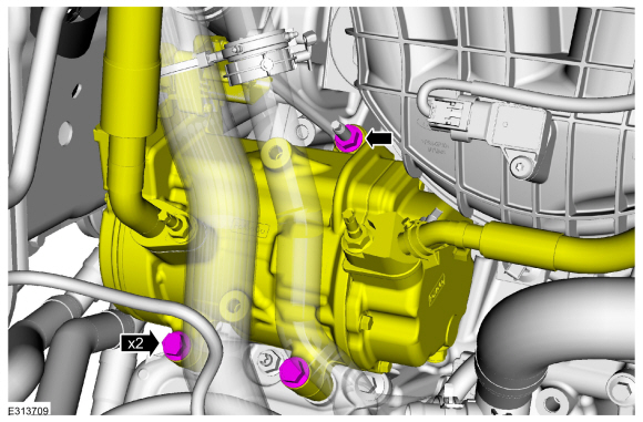
Remove the A/C compressor nut, bolts and position aside.
-
Disconnect the wire harness pin-type retainers, remove the fasteners and bracket.
-
NOTICE:
Do not loosen the engine-to-transmission bolts more then
in (
5
mm) or damage to the transmission can occur.
Loosen the engine-to-transmission bolts 5mm (0.19 in).
-
NOTICE:
Do not loosen the engine-to-transmission bolts more then
in (
5
mm) or damage to the transmission can occur.
Loosen the RH engine-to-transmission bolts 5mm (0.19 in).
-
Remove the bolt.
-
Remove the bolts.
-
Slide the transaxle away from the engine 5mm (0.19 in).
-
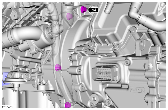
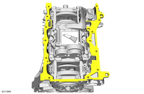
Remove the bolts and the oil pan.
-
NOTE:
This step not necessary if installing new component.
Make sure that the mating surface is clean and free of foreign material.
Refer to: RTV Sealing Surface Cleaning and Preparation (303-00 Engine System - General Information, General Procedures).
Use the General Equipment: Plastic Scraper
-
Make sure that the mating surface is clean and free of foreign material.
Refer to: RTV Sealing Surface Cleaning and Preparation (303-00 Engine System - General Information, General Procedures).
Use the General Equipment: Plastic Scraper
Installation
All vehicles
-
NOTE:
If the oil pan is not secured within 10 minutes
of sealant application, the sealant must be removed and the sealing area
cleaned with metal surface prep. Allow to dry until there is no sign of
wetness, or 10 minutes, whichever is longer. Failure to follow this
procedure can cause future oil leakage.
Apply a 3 mm (0.19 in) bead of silicone sealant.
Material: Motorcraft® High Performance Engine RTV Silicone
/ TA-357
(WSE-M4G323-A6)
-
NOTE:
Only tighten the bolts finger tight at this time.
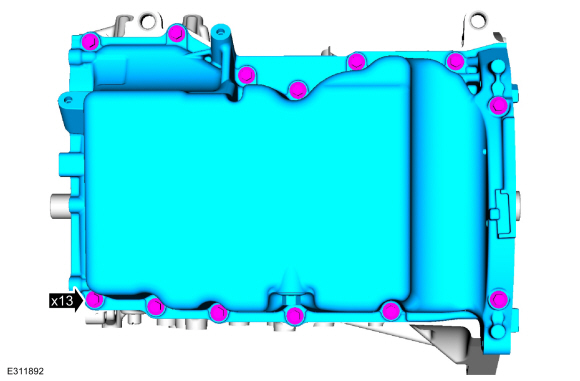
Install the oil pan and the bolts finger tight.
-
Tighten the bolts in sequence shown.
Torque:
Fasteners 1-9:
Stage 1:
177 lb.in (20 Nm)
Stage 2:
45°
Fasteners 10-11:
Stage 3:
177 lb.in (20 Nm)
Stage 4:
90°
Fasteners 12-13:
Stage 5:
177 lb.in (20 Nm)
Stage 6:
45°
-
Alternate tightening the LH and RH engine-to-transmission bolts to slide the engine and transmission together.
-
Install the bolts.
Torque:
35 lb.ft (48 Nm)
-
Install the bolt.
Torque:
35 lb.ft (48 Nm)
-
Tighten the RH engine-to-transmission bolts.
Torque:
35 lb.ft (48
Nm)
-
Tighten the LH engine-to-transmission bolts.
Torque:
35 lb.ft (48
Nm)
-
Install the bracket and fasteners and connect the electrical harness pin-type retainers.
Torque:
18 lb.ft (25 Nm)
-
Position the A/C compressor, install the nut and bolts.
Torque:
18 lb.ft (25 Nm)
-
Connect the A/C compressor electrical connectors and pin-type retainers.
-
Install the coolant pump.
Refer to: Coolant Pump (303-03C Engine Cooling, Removal and Installation).
-
Position back the coolant pump electrical connector and install the pin-type retainer.
-
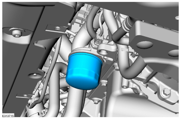
NOTE:
Lubricate the engine oil filter gasket with clean engine oil prior to installing the oil filter.
Install a new oil filter.
Refer to: Specifications (303-01C Engine, Specifications).
Torque:
133 lb.in (15 Nm)
LHD AWD/RHD AWD
-
Install the catalytic converter.
Refer to: Catalytic Converter (309-00C Exhaust System, Removal and Installation).
LHD FWD/RHD FWD
-
Install the catalytic converter.
Refer to: Catalytic Converter (309-00C Exhaust System, Removal and Installation).
All vehicles
-
Install the oil level indicator.
-
Install the cowl panel grille.
Refer to: Cowl Panel Grille (501-02 Front End Body Panels, Removal and Installation).
-
Fill the engine with clean engine oil.
Refer to: Specifications (303-01C Engine, Specifications).
Removal
With the vehicle in NEUTRAL, position it on a hoist.
Refer to: Jacking and Lifting - Overview (100-02 Jacking and Lifting, Description and Operation)...
Materials
Name
Specification
Motorcraft® Thread Sealant with PTFETA-24-B
WSK-M2G350-A2
Removal
NOTE:
Removal steps in this procedure may contain installation details...
Other information:
Removal
Release the clips and remove the floor console upper rear trim panel.
Disconnect the electrical connectors.
Remove the PATS center antenna.
Remove the nuts.
Lift upward on the PATS center antenna...
Removal
NOTE:
Removal steps in this procedure may contain installation details.
Telematics control unit (TCU) to body harness cable
Remove the floor console.
Refer to: Floor Console (501-12 Instrument Panel and Console, Removal and Installation)...
.jpg)
.jpg)
.jpg)
.jpg)
.jpg)
.jpg)
.jpg)
 Removal and Installation - Intake Manifold
 Removal and Installation - Oil Pressure Switch