Ford Escape: Supplemental Restraint System / Removal and Installation - Passenger Airbag Deactivation (PAD) Indicator
Special Tool(s) /
General Equipment
Removal
-
Remove the center registers.
Refer to: Center Registers (412-00 Climate Control System - General Information, Removal and Installation).
-
Position the console center top trim panel up for access.
-
Release the clips.
-
Release the retaining hooks.
-
Disconnect the electrical connectors and remove the floor console center top trim panel.
-
Remove the floor console LH side trim panel screw cover.
Use the General Equipment: Interior Trim Remover
-
Remove the screw, release the clips and remove the LH floor console side trim panel.
Use the General Equipment: Interior Trim Remover
-
Release the clips and remove the RH floor console side trim panel.
Use the General Equipment: Interior Trim Remover
-
Remove the USB port.
Refer to: Universal Serial Bus (USB) Port (415-00 Information and
Entertainment System - General Information, Removal and Installation).
-
Remove the floor console LH bolt.
-
Disconnect the floor console electrical connector, separate the wiring guide and remove the floor console bolt.
-
Release the clips and remove the media bin.
-
Disconnect the electrical connector.
Use the General Equipment: Interior Trim Remover
-
Release the clips and remove the trim panel.
Use the General Equipment: Interior Trim Remover
-
Remove the RH steering column opening trim panel upper screws.
Torque:
22 lb.in (2.5 Nm)
-
Position the LH front door weather-strip aside.
-
Release the clips and remove the center A-pillar trim panel.
Use the General Equipment: Interior Trim Remover
-
Release the clips and remove the LH instrument panel finish panel.
Use the General Equipment: Interior Trim Remover
-
Release the clips, disconnect the electrical connector and remove the LH steering column opening trim panel.
Use the General Equipment: Interior Trim Remover
-
Remove the RH steering column opening trim panel lower screws.
Torque:
22 lb.in (2.5 Nm)
-
Release the clips, disconnect the electrical connectors and remove the RH steering column opening trim panel.
-
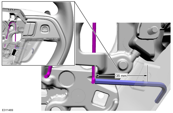
-
On both sides.
Push in and release the PAD indicator retainers.
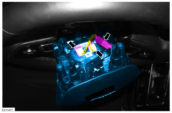
-
Remove the PAD indicator.
Installation
-
To install, reverse the removal procedure.
Removal
WARNING:
The following procedure prescribes critical repair steps
required for correct supplemental restraint system operation during a
crash...
Removal
WARNING:
The following procedure prescribes critical repair steps
required for correct restraint system operation during a crash. Follow
all notes and steps carefully...
Other information:
Special Tool(s) /
General Equipment
303-476
(T94P-9472-A)
Socket, Exhaust Gas Oxygen SensorTKIT-1994-LM/MTKIT-1994-FTKIT-1994-FLM/FM
Strap Wrench
Floor Crane
Adjustable Mounting Arm
Oil Drain Equipment
Hose Clamp Remover/Installer
Fluid Container
Powertrain Jack
Wooden Block
Materials
Name
Specification
Motorcraft® Penetrating and Lock..
Global Customer Symptom Code (GCSC) Chart
Diagnostics in this manual assume a certain skill level and knowledge of Ford-specific diagnostic practices.REFER to: Diagnostic Methods (100-00 General Information, Description and Operation).
Symptom
Action
Lighting/Glass/Vision >
Windows/Glass >
Door >
Power Function
GO to Pinpoint Test A
Lighting/Glass/Vision >
Windo..
.jpg)
.jpg)
.jpg)
.jpg)
.jpg)
.jpg)
.jpg)
.jpg)
.jpg)
.jpg)
.jpg)
.jpg)
.jpg)
.jpg)
.jpg)
 Removal and Installation - Passenger Airbag
 Removal and Installation - Restraints Control Module (RCM)