Ford Escape: Rear Seats / Removal and Installation - Rear Seat
Special Tool(s) / General Equipment
| Interior Trim Remover |
Removal
.jpg) WARNING:
The following procedure describes critical repair steps
required for correct seat component installation. Follow all notes and
steps carefully. Do not place any objects between the seat components
and the body of the vehicle, nor any objects within a joint internal to
the seat structure. Failure to follow step instructions may result in
incorrect operation of the seat components and increases the risk of
serious personal injury.
WARNING:
The following procedure describes critical repair steps
required for correct seat component installation. Follow all notes and
steps carefully. Do not place any objects between the seat components
and the body of the vehicle, nor any objects within a joint internal to
the seat structure. Failure to follow step instructions may result in
incorrect operation of the seat components and increases the risk of
serious personal injury.
NOTE: LH (left hand) shown, RH (right hand) similar.
NOTE: Removal steps in this procedure may contain installation details.
-
Depower the SRS .
Refer to: Supplemental Restraint System (SRS) Depowering (501-20B Supplemental Restraint System, General Procedures).
-
Position the rear seat to the furthest rearward position.
.jpg) |
-
Release the tabs and remove the rear seat front bolt covers.
Use the General Equipment: Interior Trim Remover
.jpg) |
-
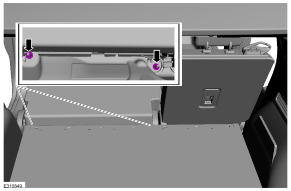
Remove the rear seat front bolts.
Torque: 30 lb.ft (40 Nm)
.jpg) |
-
Disconnect the rear seat electrical connector.
 |
-
Position the rear seat to the furthest forward position.
.jpg) |
-
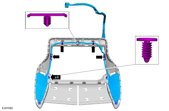
Position the rear seat seatbelt through the seatbelt guide.
.jpg) |
-
Fold the rear seat backrest into the fold flat position.
.jpg) |
-
Remove the rear seat nuts.
Torque: 52 lb.ft (70 Nm)
 |
-
Remove the rear seat.
.jpg) |
Installation
NOTE: During installation, make sure the seatbelt webbing is not twisted and the seatbelts and buckles are accessible to the occupants.
-
To install, reverse the removal procedure.
-
Repower the SRS .
Refer to: Supplemental Restraint System (SRS) Repowering (501-20B Supplemental Restraint System, General Procedures).
 Removal and Installation - Rear Head Restraint Guide Sleeve
Special Tool(s) /
General Equipment
Flat Headed Screw Driver
Removal
Outboard head restraint guide sleeves
Push the rear seat outboard head restraint release buttons...
 Removal and Installation - Rear Seat Armrest
Special Tool(s) /
General Equipment
Interior Trim Remover
Removal
NOTE:
Removal steps in this procedure may contain installation details...
Other information:
Ford Escape 2020-2026 Owners Manual: Normal Scheduled Maintenance
Intelligent Oil-Life Monitor™ Your vehicle has an Intelligent Oil-Life Monitor that determines when you should change the engine oil based on how you use your vehicle. By using several important factors in its calculations, the monitor helps reduce the cost of owning your vehicle and reduces environmental waste at the same time...
Ford Escape 2020-2026 Service Manual: Removal and Installation - Transmission Fluid Cooler
Removal Remove the A/C condenser. Refer to: Transmission Fluid Cooler (307-02A Transmission Cooling - 8-Speed Automatic Transmission – 8F35/8F40, Removal and Installation). Release the clips and remove the transmission fluid cooler from the radiator...
Categories
- Manuals Home
- 4th Generation Ford Escape Owners Manual
- 4th Generation Ford Escape Service Manual
- Rear View Camera
- Symbols Glossary
- General Procedures - Transmission Fluid Level Check
- New on site
- Most important about car
Engine Oil
Engine Oil Dipstick Overview
