Ford Escape: Rear Seats / Removal and Installation - Rear Head Restraint Guide Sleeve
Special Tool(s) / General Equipment
| Flat Headed Screw Driver |
Removal
Outboard head restraint guide sleeves
-
-
Push the rear seat outboard head restraint release buttons.
-
Remove the rear seat outboard head restraint.
-
Push the rear seat outboard head restraint release buttons.
.jpg) |
-
-
Push down on the rear seat backrest cover to
gain access to the outboard head restraint guide sleeve retaining clip.
-
Remove and discard the outboard head restraint guide sleeve retaining clip.
-
Push down on the rear seat backrest cover to
gain access to the outboard head restraint guide sleeve retaining clip.
 |
Center head restraint guide sleeves
-
-
Push the rear seat center head restraint release button.
-
Remove the rear seat center head restraint.
-
Push the rear seat center head restraint release button.
.jpg) |
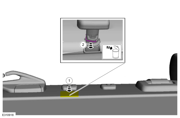
All head restraint guide sleeves
-
NOTE: Follow the unique instructions or graphics for this step in the installation.
Using a flat head screwdriver, release the head restraint guide sleeve locking tab. Remove the head restraint guide sleeve and discard.
Use the General Equipment: Flat Headed Screw Driver
.jpg) |
Installation
-
NOTICE: Always install new head restraint guide sleeves. Difficult adjustment of the head restraint may occur. Failure to follow these instructions may result in component failure.
NOTICE: The head restraint guide sleeves are not interchangeable. Failure to install the correct head restraint guide sleeve at the correct position may result in component failure.
To install, reverse the removal procedure.
-
Allow the head restraint guide sleeve to slide freely
through the backrest foam and backrest trim cover. Using hand pressure,
twist the head restraint guide sleeve while pushing it into the backrest
frame until the tab is locked into place.
.jpg) |
 Rear Seats
..
 Removal and Installation - Rear Seat
Special Tool(s) /
General Equipment
Interior Trim Remover
Removal
WARNING:
The following procedure describes critical repair steps
required for correct seat component installation...
Other information:
Ford Escape 2020-2026 Service Manual: Description and Operation - Pump Assembly - Hybrid Electric Vehicle (HEV)
Transmission Fluid Pump The transmission fluid pump is an internal pump bolted to the transmission case. The transmission fluid pump is turned by the input shaft and circulates transmission fluid through the transmission for lubrication and through an oil-to-air cooler mounted in the front of the radiator for transmission cooling...
Ford Escape 2020-2026 Owners Manual: Using Voice Recognition
This system helps you control many features using voice commands. This allows you to keep your hands on the wheel and focus on what is around you. Initiating a Voice Session Press the voice button. A list of available voice commands appears in the display...
Categories
- Manuals Home
- 4th Generation Ford Escape Owners Manual
- 4th Generation Ford Escape Service Manual
- Rear View Camera
- Electric Parking Brake
- Fuel Quality
- New on site
- Most important about car
Adjusting the Seatbelts During Pregnancy
WARNING: Always ride and drive with your seatback upright and properly fasten your seatbelt. Fit the lap portion of the seatbelt snugly and low across the hips. Position the shoulder portion of the seatbelt across your chest. Pregnant women must follow this practice. See the following figure.
