Ford Escape: Side Panel Sheet Metal Repairs / Removal and Installation - Rocker Panel
Special Tool(s) /
General Equipment
| Resistance Spotwelding Equipment |
| Spherical Cutter |
| Air Body Saw |
| 8 mm Drill Bit |
| MIG/MAG Welding Equipment |
| Spot Weld Drill Bit |
| Locking Pliers |
Materials
| Name |
Specification |
Metal Bonding Adhesive
TA-1, TA-1-B, 3M™ 08115, LORD Fusor® 108B, Henkel Teroson EP 5055 |
-
|
Flexible Foam Repair
3M™ 08463, LORD Fusor® 121 |
-
|
Removal
.jpg) WARNING:
Electric vehicles damaged by a crash may have compromised
high voltage safety systems and present a potential high voltage
electrical shock hazard. Exercise caution and wear appropriate Personal
Protective Equipment (PPE) safety gear, including high voltage safety
gloves and boots. Remove all metallic jewelry, including watches and
rings. Isolate the HV system as directed by the Ford Emergency Response
Guide for the vehicle. Failure to follow these instructions may result
in serious personal injury or death.
WARNING:
Electric vehicles damaged by a crash may have compromised
high voltage safety systems and present a potential high voltage
electrical shock hazard. Exercise caution and wear appropriate Personal
Protective Equipment (PPE) safety gear, including high voltage safety
gloves and boots. Remove all metallic jewelry, including watches and
rings. Isolate the HV system as directed by the Ford Emergency Response
Guide for the vehicle. Failure to follow these instructions may result
in serious personal injury or death.
NOTICE:
Battery electric vehicle (BEV), hybrid electric vehicle
(HEV) and plug-in hybrid electric vehicle (PHEV) contain a high-voltage
battery. Before cutting or welding near the high-voltage battery it must
be removed to avoid damage.
NOTE:
Left hand (LH) side shown, right hand (RH) side similar.
NOTE:
The rocker panel reinforcement is construct of dual phase
(DP) 800 steel and my not be sectioned. It must be replaced at factory
seams.
-
WARNING:
Before beginning any service procedure in this
manual, refer to health and safety warnings in section 100-00 General
Information. Failure to follow this instruction may result in serious
personal injury.
Refer to: Health and Safety Precautions (100-00 General Information, Description and Operation).
Refer to: High Voltage System Health and Safety Precautions - Overview (100-00 General Information, Description and Operation).
-
Depower the SRS .
Refer to: Supplemental Restraint System (SRS) Depowering (501-20B Supplemental Restraint System, General Procedures).
-
If Necessary:
Dimensionally restore the vehicle to pre-damage condition.
Refer to: Body and Frame (501-26 Body Repairs - Vehicle Specific Information and Tolerance Checks, Description and Operation).
-
Carefully cut the outer panel only.
Use the General Equipment: Air Body Saw
Use the General Equipment: Spherical Cutter
-
Remove the A-pillar reinforcement.
Refer to: A-Pillar Outer Panel Section and Reinforcement (501-29 Side Panel Sheet Metal Repairs, Removal and Installation).
-
Remove the B-pillar outer panel and B-pillar only.
Refer to: B-Pillar Outer Panel (501-29 Side Panel Sheet Metal Repairs, Removal and Installation).
Refer to: B-Pillar and Reinforcement (501-29 Side Panel Sheet Metal Repairs, Removal and Installation).
-
NOTE:
Pay particular attention to the location of adhesives and sealers to aid in installation.
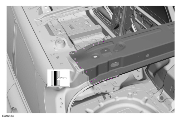
Remove the remaining portion of the outer rocker panel.
Use the General Equipment: Spot Weld Drill Bit
-
Remove the welds.
Use the General Equipment: Spot Weld Drill Bit
-
NOTE:
Pay particular attention to the location of adhesives and sealers to aid in installation.
Remove the rocker panel.
Installation
WARNING:
Electric vehicles damaged by a crash may have compromised
high voltage safety systems and present a potential high voltage
electrical shock hazard. Exercise caution and wear appropriate Personal
Protective Equipment (PPE) safety gear, including high voltage safety
gloves and boots. Remove all metallic jewelry, including watches and
rings. Isolate the HV system as directed by the Ford Emergency Response
Guide for the vehicle. Failure to follow these instructions may result
in serious personal injury or death.
NOTICE:
Battery electric vehicle (BEV), hybrid electric vehicle
(HEV) and plug-in hybrid electric vehicle (PHEV) contain a high-voltage
battery. Before cutting or welding near the high-voltage battery it must
be removed to avoid damage.
NOTICE:
The high-voltage battery in a battery electric vehicle
(BEV), hybrid electric vehicle (HEV) or plug-in hybrid electric vehicle
(PHEV) can be affected and damaged by excessively high temperatures. The
temperature in some body shop paint booths can exceed 60° C (140° F).
Therefore, during refinishing operations, the paint booth temperature
must set at or below 60° C (140° F) with a bake time of 45 minutes or
less. Temperatures in excess of 60° C (140° F) or bake durations longer
than 45 minutes will require the high-voltage battery be removed from
the vehicle prior to placing in the paint booth.
NOTICE:
If refinishing cure temperatures exceed 60° C (140° F), the
charge port light ring on plug-in vehicles must be removed.
NOTE:
Factory welds may be substituted with resistance or metal
inert gas (MIG) plug welds. Resistance welds may not be placed directly
over original location. They must be placed adjacent to original
location and match factory welds in quantity. Metal inert gas (MIG) plug
welds must equal factory welds in both location and quantity.
NOTE:
Left hand (LH) side shown, right hand (RH) side similar.
-
WARNING:
Before beginning any service procedure in this
manual, refer to health and safety warnings in section 100-00 General
Information. Failure to follow this instruction may result in serious
personal injury.
Refer to: Health and Safety Precautions (100-00 General Information, Description and Operation).
Refer to: High Voltage System Health and Safety Precautions - Overview (100-00 General Information, Description and Operation).
-
Drill plug weld holes.
Use the General Equipment: 8 mm Drill Bit
-
Sand to remove old adhesive and clean.
-
Apply adhesive.
Material: Metal Bonding Adhesive
/ TA-1, TA-1-B, 3M™ 08115, LORD Fusor® 108B, Henkel Teroson EP 5055
-
Install, properly position and clamp the rocker panel.
Use the General Equipment: Locking Pliers
-
Install the welds.
Use the General Equipment: MIG/MAG Welding Equipment
-
Install the welds. Complete welding with outer side panels.
Use the General Equipment: Resistance Spotwelding Equipment
-
Reinforcement Only:
Install the A-pillar reinforcement.
Refer to: A-Pillar Outer Panel Section and Reinforcement (501-29 Side Panel Sheet Metal Repairs, Removal and Installation).
-
B-Pillar Inner Only:
Install the B-pillar.
Refer to: B-Pillar and Reinforcement (501-29 Side Panel Sheet Metal Repairs, Removal and Installation).
-
Cut the service panel to fit the repair area.
Use the General Equipment: Air Body Saw
Use the General Equipment: Spherical Cutter
-
Drill plug weld holes.
Use the General Equipment: 8 mm Drill Bit
-
Apply adhesive.
Material: Metal Bonding Adhesive
/ TA-1, TA-1-B, 3M™ 08115, LORD Fusor® 108B, Henkel Teroson EP 5055
-
Install, properly position and clamp the service part.
Use the General Equipment: Locking Pliers
-
Install the welds.
Use the General Equipment: Resistance Spotwelding Equipment
-
Install the welds.
Use the General Equipment: Resistance Spotwelding Equipment
-
Install the welds.
Use the General Equipment: Resistance Spotwelding Equipment
-
Install the welds.
Use the General Equipment: MIG/MAG Welding Equipment
-
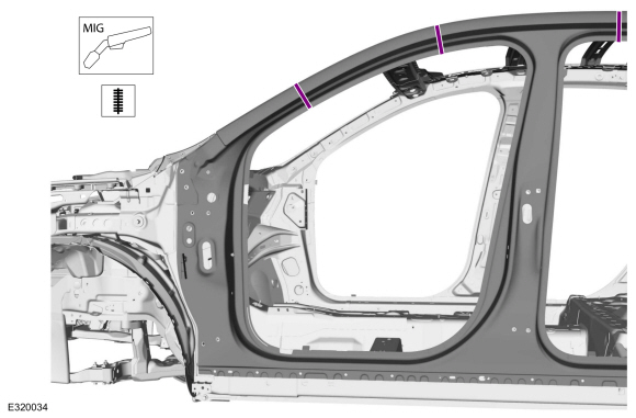
Completely seam weld the sectioning joints.
Use the General Equipment: MIG/MAG Welding Equipment
-
Apply NVH foam sealant in areas noted during removal.
Material: Flexible Foam Repair
/ 3M™ 08463, LORD Fusor® 121
-
Cut the service panel to fit the repair area.
Use the General Equipment: Air Body Saw
Use the General Equipment: Spherical Cutter
-
Drill plug weld holes.
Use the General Equipment: 8 mm Drill Bit
-
Apply adhesive.
Material: Metal Bonding Adhesive
/ TA-1, TA-1-B, 3M™ 08115, LORD Fusor® 108B, Henkel Teroson EP 5055
-
Install, properly position and clamp the service part.
Use the General Equipment: Locking Pliers
-
Install the welds.
Use the General Equipment: Resistance Spotwelding Equipment
-
Install the welds.
Use the General Equipment: MIG/MAG Welding Equipment
-
Completely seam welds the sectioning joints.
Use the General Equipment: MIG/MAG Welding Equipment
-
Metal finish all welds using typical metal finishing techniques and materials.
-
Install NVH foam sealant in areas noted during removal.
Material: Flexible Foam Repair
/ 3M™ 08463, LORD Fusor® 121
-
Install the roof.
Refer to: Roof Panel (501-28 Roof Sheet Metal Repairs, Removal and Installation).
-
Seam Sealing:
All seams must be sealed to production level.
-
Sand to remove old adhesive, paint, e-coat and clean.
-
Apply a Ford approved epoxy-based primer and allow to dry.
-
Mask off the area.
-
Refinish the entire repair using a Ford approved paint system.
-
Unmask the area.
-
Install the windshield.
Refer to: Fixed Glass (501-11 Glass, Frames and Mechanisms, General Procedures).
-
Install the front door hinges at the body.
Torque:
22 lb.ft (30 Nm)
-
Install the bolt.
Torque:
35 lb.ft (47 Nm)
-
Install the body plugs.
-
Install the rocker panel moulding.
Refer to: Rocker Panel Moulding (501-08 Exterior Trim and Ornamentation, Removal and Installation).
-
Reposition the carpet and wiring harnesses to original locations.
-
Install the front and rear door opening weather-strips.
-
Install the front door striker and rear door hinges at the body.
Torque:
1:
22 lb.ft (30 Nm)
2:
18 lb.ft (25 Nm)
-
Install the B-pillar interior trim.
Refer to: B-Pillar Trim Panel (501-05 Interior Trim and Ornamentation, Removal and Installation).
-
Install the fender and splash shield.
Refer to: Fender (501-02 Front End Body Panels, Removal and Installation).
Refer to: Fender Splash Shield (501-02 Front End Body Panels, Removal and Installation).
-
Install the front and rear doors.
Refer to: Front Door (501-03 Body Closures, Removal and Installation).
Refer to: Rear Door (501-03 Body Closures, Removal and Installation).
-
Install the front and rear door opening tread plates.
-
Align the doors.
Refer to: Rear Door Alignment (501-03 Body Closures, General Procedures).
Refer to: Front Door Alignment (501-03 Body Closures, General Procedures).
-
Restore corrosion protection.
Refer to: Corrosion Prevention (501-25 Body Repairs - General Information, General Procedures).
-
Repower the SRS .
Refer to: Supplemental Restraint System (SRS) Repowering (501-20B Supplemental Restraint System, General Procedures).
Special Tool(s) /
General Equipment
Resistance Spotwelding Equipment
Scraper for Straight Edges
Hot Air Gun
Spot Weld Drill Bit
Locking Pliers
Materials
Name
Specification
Metal Bonding AdhesiveTA-1, TA-1-B, 3M™ 08115, LORD Fusor® 108B, Henkel Teroson EP 5055
-
Seam SealerTA-2-B, 3M™ 08308, LORD Fusor® 803DTM
-
Removal
..
Other information:
Special Tool(s) /
General Equipment
204-069
(T81P-1104-C)
Remover/Installer, Front Wheel Hub
205-153
(T80T-4000-W)
Handle
307-557Installer, Ball BearingTKIT-2005U-FLMTKIT-2005U-LMTKIT-2006U-FLM/LMTKIT-2006UF/FM
308-968Installer, Input Shaft Seal
308-971Remover, Input Sleeve
308-972Installer, Input Sleeve
308-973Remover, PTU Input Sleeve
Hyd..
Special Tool(s) /
General Equipment
Interior Trim Remover
Removal
NOTE:
Removal steps may contain installation details.
NOTE:
If installing a new module, it is necessary to
upload the module configuration information to the scan tool prior to
removing the module. This information must be downloaded into the new
module after installation. If installing a new module, it i..
.jpg)
.jpg)
.jpg)
.jpg)
.jpg)
.jpg)
.jpg)
.jpg)
.jpg)
.jpg)
.jpg)
.jpg)
.jpg)
.jpg)
.jpg)
.jpg)
.jpg)
.jpg)
.jpg)
.jpg)
.jpg)
.jpg)
.jpg)
.jpg)
.jpg)
.jpg)
.jpg)
.jpg)
.jpg)
.jpg)
.jpg)
.jpg)
.jpg)
.jpg)
.jpg)

 Removal and Installation - Rocker Panel Inner Reinforcement