Ford Escape: Fuel Charging and Controls - Turbocharger - 1.5L EcoBoost (132kW/180PS) – I3 (Y1) / Removal and Installation - Turbocharger
Special Tool(s) /
General Equipment
| Hose Clamp Remover/Installer |
Materials
| Name |
Specification |
Motorcraft® Metal Brake Parts Cleaner
PM-4-A, PM-4-B, APM-4-C |
-
|
Removal
NOTICE:
The turbocharger compressor vanes can be damaged by even the
smallest particles. When removing any turbocharger or engine air intake
system component, ensure that no debris enters the system. Failure to
do so may result in damage to the turbocharger.
NOTICE:
Special attention needs to be given to the sealing ports for
the oil feed, the oil drain, and the coolant lines, on turbocharged
engines. The sealing ports must be totally clean and free from O-ring
residue, have no damage to the sealing surface and the lines to ensure
that there are no leaks or repeat repairs.
All Vehicles
-
Drain the cooling system.
Refer to: Engine Cooling System Draining, Vacuum Filling and Bleeding
(303-03A Engine Cooling - 1.5L EcoBoost (132kW/180PS) – I3 (Y1), General
Procedures).
-
Remove the cowl panel grille.
Refer to: Cowl Panel Grille (501-02 Front End Body Panels, Removal and Installation).
-
Remove the air cleaner outlet pipe.
Refer to: Air Cleaner Outlet Pipe (303-12A Intake Air Distribution and
Filtering - 1.5L EcoBoost (132kW/180PS) – I3 (Y1), Removal and
Installation).
-
Remove the charge air cooler intake pipe.
Refer to: Charge Air Cooler (CAC) Intake Pipe (303-12A Intake Air
Distribution and Filtering - 1.5L EcoBoost (132kW/180PS) – I3 (Y1),
Removal and Installation).
-
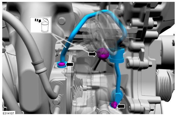
Disconnect the turbocharger control hose.
Use the General Equipment: Hose Clamp Remover/Installer
-
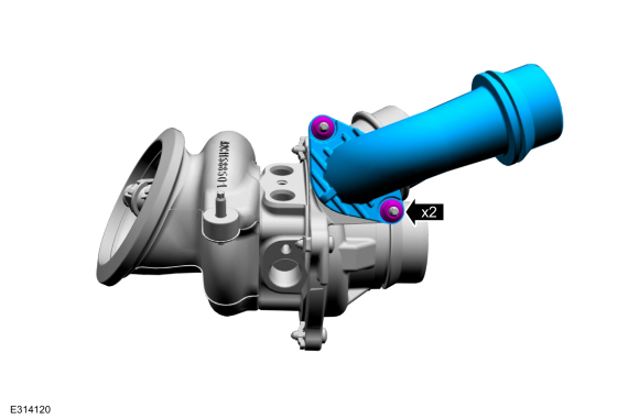
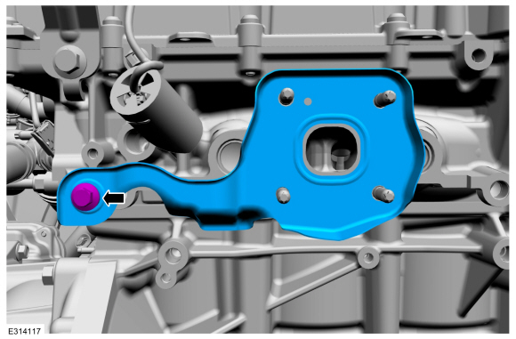
Remove the bolts, then remove and discard turbocharger oil supply tube. Discard the designated bolt.
-
Loosen the turbocharger coolant tube bolt, then
disconnect the turbocharger coolant tubes and move out of the way.
-
NOTICE:
Do not use a metal brush, damage to sealing area will result in leaks.
-
Remove and discard the turbocharger coolant tube O-ring seals.
-
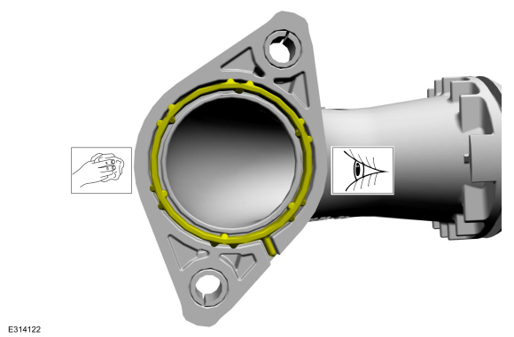
Inspect the turbocharger tube and the sealing
surfaces. Ensure that the retaining bracket is not bent, check for
square-ness of the retaining bracket to the O-ring area. Use brake
cleaner and a nylon brush to clean.
Material: Motorcraft® Metal Brake Parts Cleaner
/ PM-4-A, PM-4-B, APM-4-C
-
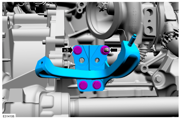
Remove the bolts and the nut, then remove the turbocharger heat shield.
LHD FWD/RHD FWD
-
Remove the catalytic converter.
Refer to: Catalytic Converter (309-00A Exhaust System - 1.5L EcoBoost (132kW/180PS) – I3 (Y1), Removal and Installation).
-
Remove the bolts and the nut, then remove the bracket.
LHD AWD/RHD AWD
-
Remove the power transfer unit.
Refer to: Power Transfer Unit - Vehicles With: Power Transfer Unit
Oil-to-Coolant Cooler (307-07B Power Transfer Unit - 1.5L EcoBoost
(132kW/180PS) – I3 (Y1), Removal).
Refer to: Power Transfer Unit - Vehicles Without: Power Transfer Unit
Oil-to-Coolant Cooler (307-07B Power Transfer Unit - 1.5L EcoBoost
(132kW/180PS) – I3 (Y1), Removal).
All Vehicles
-
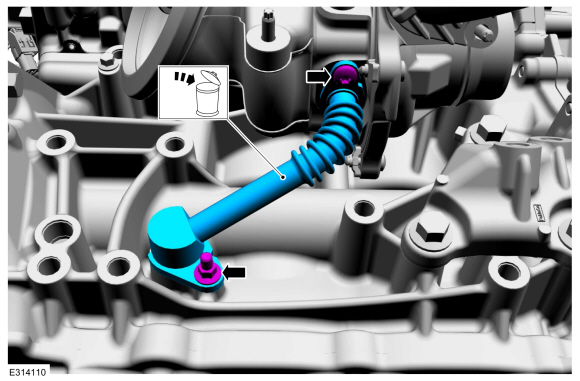
Remove the bolts, then remove and discard the turbocharger oil return tube.
-
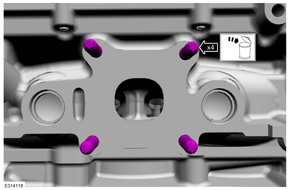
Remove and discard the turbocharger mounting nuts, then remove the turbocharger.
-
Remove the bolt, then remove and discard the turbocharger gasket.
-
Remove and discard the turbocharger mounting studs.
-
Only if needed, remove the turbocharger elbow adapter nuts, then remove elbow adapter.
-
Only if needed, remove the turbocharger studs.
-
If the turbocharger elbow adapter was removed, then inspect, clean and replace the gasket as needed.
Installation
All Vehicles
-
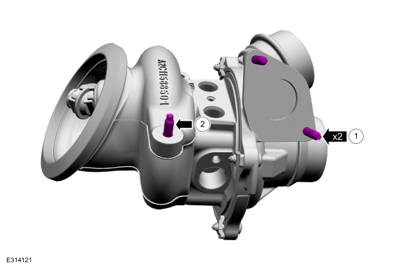
If removed, install and tighten the turbocharger studs.
Torque:
1, tighten to: :
36 lb.in (4.1 Nm)
2, tighten to: :
44 lb.in (5 Nm)
-
If removed, install the turbocharger elbow adapter, then install and tighten nuts.
Torque:
97 lb.in (11 Nm)
-
Install and tighten the new turbocharger mounting studs.
Torque:
89 lb.in (10 Nm)
-
Install the new turbocharger gasket, then install and tighten the bolt.
Torque:
17 lb.ft (23 Nm)
-
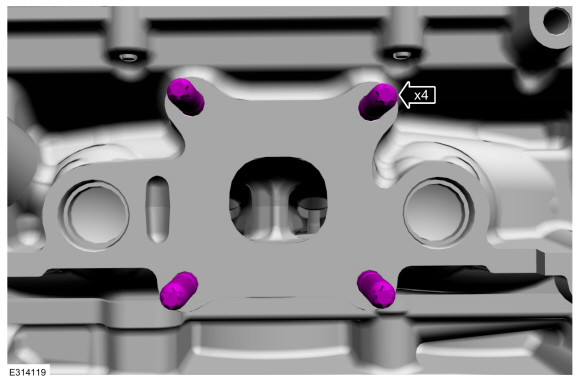
Install the turbocharger, then install and tighten the new turbocharger mounting nuts.
Torque:
Stage 1:
Tighten in the sequence shown to: :
17 lb.ft (23 Nm)
Stage 2:
Re-tighten in the sequence shown to: :
17 lb.ft (23 Nm)
-
NOTICE:
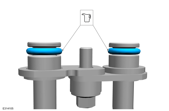
Ensure that new O-rings are used.
Install the new O-ring seals, if already not installed, then lubricate them with clean engine oil.
Refer to: Specifications (303-01B Engine - 2.0L EcoBoost (177kW/240PS) – MI4, Specifications).
-
NOTICE:
Do not use a metal brush, damage to sealing area will result in leaks.
NOTE:
The oil return tube must be fully seated prior to fastener rundown.
-
Carefully use a nylon brush to remove the old
O-ring residue, use brake cleaner to rinse the O-ring residue out of the
turbocharger tube O-ring bore. Inspect the area for deep scratches and
gouges. Install new components if needed.
-
Install the oil return tube, then install and tighten the bolts.
Material: Motorcraft® Metal Brake Parts Cleaner
/ PM-4-A, PM-4-B, APM-4-C
Torque:
97 lb.in (11 Nm)
LHD AWD/RHD AWD
-
Install the power transfer unit.
Refer to: Power Transfer Unit - Vehicles With: Power Transfer Unit
Oil-to-Coolant Cooler (307-07B Power Transfer Unit - 1.5L EcoBoost
(132kW/180PS) – I3 (Y1), Installation).
Refer to: Power Transfer Unit - Vehicles Without: Power Transfer Unit
Oil-to-Coolant Cooler (307-07B Power Transfer Unit - 1.5L EcoBoost
(132kW/180PS) – I3 (Y1), Installation).
LHD FWD/RHD FWD
-
Install the bracket, then install and tighten the bolts and the nut.
Torque:
35 lb.ft (48 Nm)
-
Install the catalytic converter.
Refer to: Catalytic Converter (309-00A Exhaust System - 1.5L EcoBoost (132kW/180PS) – I3 (Y1), Removal and Installation).
All Vehicles
-
Install the turbocharger heat shield, then install and tighten the turbocharger heat shield bolts and nut.
Torque:
Tighten the bolts to: :
115 lb.in (13 Nm)
Tighten the nut to: :
115 lb.in (13 Nm)
-
Install the new the turbocharger coolant tube O-ring seals, lubricate with clean engine coolant.
Refer to: Specifications (303-01A Engine - 1.5L EcoBoost (132kW/180PS) – I3 (Y1), Specifications).
-
NOTICE:
Do not use a metal brush, damage to sealing area will result in leaks.
-
Carefully use a nylon brush to remove the old
O-ring residue and use brake cleaner to rinse the O-ring residue out of
the turbocharger O-ring bores. Inspect the area for deep scratches and
gouges. Install new components if needed.
-
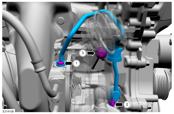
Install the upper turbocharger coolant return
tube first, then install the lower turbocharger supply tube and bolt.
Tighten the bolt.
Material: Motorcraft® Metal Brake Parts Cleaner
/ PM-4-A, PM-4-B, APM-4-C
Torque:
89 lb.in (10 Nm)
-
NOTICE:
A new turbocharger oil supply tube filter must
be used. (Part of the oil supply tube.) Failure to use a new filter will
cause turbocharger failure.
Install the new O-rings if not already installed. Lubricate the O-ring seals with clean engine oil.
Refer to: Specifications (303-01A Engine - 1.5L EcoBoost (132kW/180PS) – I3 (Y1), Specifications).
-
NOTE:
The oil supply tube must be fully seated prior to fastener tightening.
-
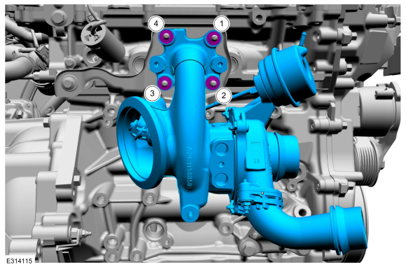
Install and fully seat the new turbocharger oil
supply tube, install and finger tighten the bolts at this stage.
Torque:
1 :
89 lb.in (10 Nm)
2 :
89 lb.in (10 Nm)
3 :
22 lb.ft (30 Nm)
-
Connect the turbocharger control hose.
Use the General Equipment: Hose Clamp Remover/Installer
-
Install the charge air cooler intake pipe.
Refer to: Charge Air Cooler (CAC) Intake Pipe (303-12A Intake Air
Distribution and Filtering - 1.5L EcoBoost (132kW/180PS) – I3 (Y1),
Removal and Installation).
-
Install the air cleaner outlet pipe.
Refer to: Air Cleaner Outlet Pipe (303-12A Intake Air Distribution and
Filtering - 1.5L EcoBoost (132kW/180PS) – I3 (Y1), Removal and
Installation).
-
Install the cowl panel grille.
Refer to: Cowl Panel Grille (501-02 Front End Body Panels, Removal and Installation).
-
Check and top off the engine oil as needed.
Refer to: Specifications (303-01B Engine - 2.0L EcoBoost (177kW/240PS) – MI4, Specifications).
-
Fill and bleed the cooling system.
Refer to: Engine Cooling System Draining, Vacuum Filling and Bleeding
(303-03A Engine Cooling - 1.5L EcoBoost (132kW/180PS) – I3 (Y1), General
Procedures).
Diagnostic Trouble Code (DTC) Chart
Diagnostics in this manual assume a certain skill level and knowledge of Ford-specific diagnostic practices. REFER to: Diagnostic Methods (100-00 General Information, Description and Operation)...
Materials
Name
Specification
Motorcraft® Metal Brake Parts CleanerPM-4-A, PM-4-B, APM-4-C
-
Removal
Drain the cooling system...
Other information:
Special Tool(s) /
General Equipment
Wooden Block
DISASSEMBLY
NOTICE:
Failure to follow the instructions below may result in damage to the TPMS .
NOTICE:
The TPMS
sensor is mounted to the valve stem. Removal of the valve stem
requires dismounting the tire from the wheel and removal of the TPMS sensor...
Doors and Locks – Warning Lamps
Door Ajar Warning Lamp
It illuminates when you switch
the ignition on and remains on if
any door or the hood is open.
Doors and Locks – Information Messages
Doors and Locks – Frequently Asked Questions
Can accessories such as steps or handles be used with the latch
assembly?
Do not use the door latch assembly to
attach any accessory, such as handles
or ..
.jpg)
.jpg)
.jpg)
.jpg)
.jpg)
.jpg)
.jpg)
.jpg)
.jpg)
.jpg)
 Diagnosis and Testing - Turbocharger Controls
 Removal and Installation - Turbocharger Coolant Return Tube