Ford Escape: Power Brake Actuation / Removal and Installation - Brake Booster
Removal
NOTE: Removal steps in this procedure may contain installation details.
-
Remove the battery tray.
Refer to: Battery Tray - 1.5L EcoBoost (132kW/180PS) – I3 (Y1)/2.0L EcoBoost (177kW/240PS) – MI4 (414-01 Battery, Mounting and Cables, Removal and Installation).
-
Remove the brake master cylinder.
Refer to: Brake Master Cylinder - Vehicles With: Vacuum Brake Booster (206-06 Hydraulic Brake Actuation, Removal and Installation).
-
Detach the vacuum check valve from the booster and position aside.
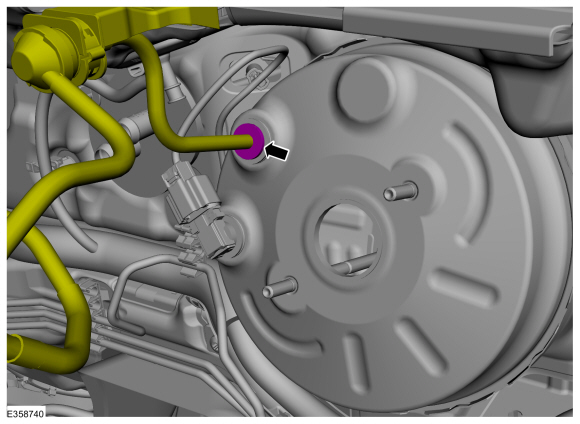 |
-
If equipped.
Disconnect the brake vacuum sensor electrical connectors.
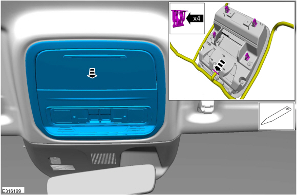 |
-
NOTICE: Do not service the brake pedal or brake booster without first removing the stoplamp switch. This switch must be removed with the brake pedal in the at-rest position. The switch plunger must be compressed for the switch to rotate in the bracket. Attempting to remove the switch when the plunger is extended (during pedal apply) will result in damage to the switch.
Remove the stoplamp switch.
Refer to: Stoplamp Switch (417-01 Exterior Lighting, Removal and Installation).
-
Remove and discard the booster push rod clevis-locking pin.
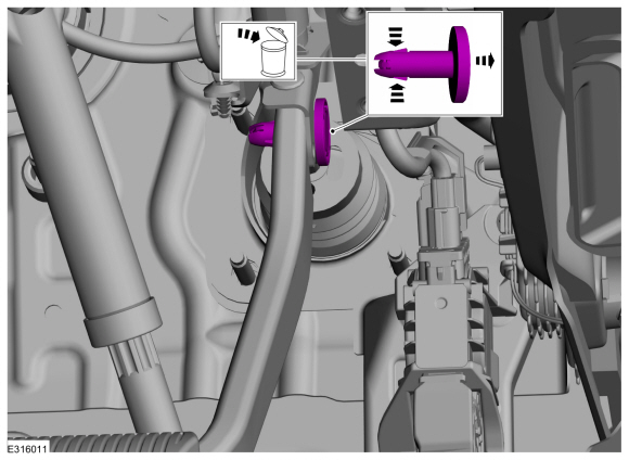 |
-
Remove the nuts.
Torque: 18 lb.ft (25 Nm)
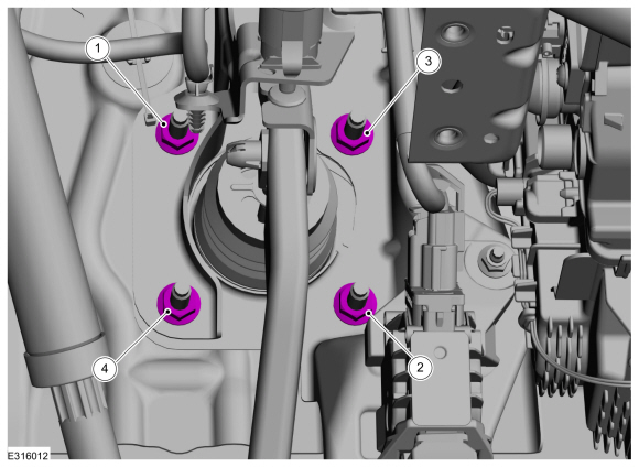 |
-
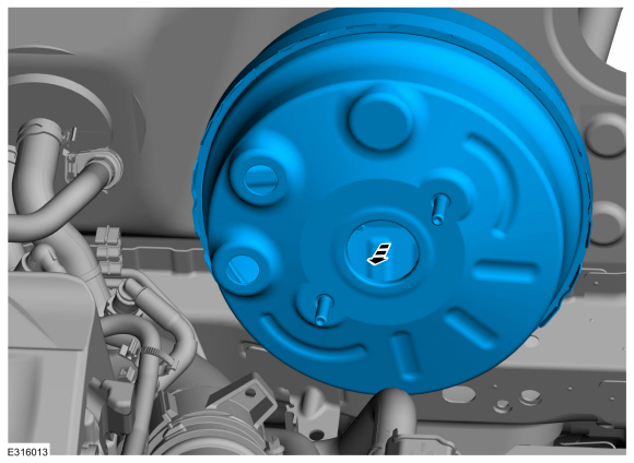
Remove the brake booster.
 |
Installation
-
NOTICE: Do not press, pull or otherwise move the brake pedal while installing the stoplamp switch. The switch must be installed with the booster push rod attached to the brake pedal and with the brake pedal in the at-rest position. Installing the switch with the brake pedal in any other position will result in incorrect adjustment and may damage the switch.
To install, reverse the removal procedure.


Other information:
Ford Escape 2020-2026 Service Manual: Removal and Installation - Cruise Control Module (CCM)
Removal NOTE: Removal steps in this procedure may contain installation details. Remove the front bumper cover. Refer to: Front Bumper Cover (501-19 Bumpers, Removal and Installation). Remove the air deflector. Remove the pushpins. Release the tabs and remove the air deflector. Detach the wire harness retainers and..
Ford Escape 2020-2026 Service Manual: Removal and Installation - Rear Brake Flexible Hose
Removal WARNING: Service actions on vehicles equipped with electronic brake booster and electronic parking brakes may cause unexpected brake application, which could result in injury to hands or fingers. Put the brake system into service mode prior to servicing or removing any brake components. Failure to follow this instruction may result in serious personal injury. NOTICE: ..
Categories
- Manuals Home
- 4th Generation Ford Escape Owners Manual
- 4th Generation Ford Escape Service Manual
- Switching the Lane Keeping System On and Off. Switching the Lane Keeping System Mode. Alert Mode
- General Procedures - Transmission Fluid Level Check
- Power Outlet - Vehicles With: 12V Power Outlet
- New on site
- Most important about car
Push Button Ignition Switch

Switching the Ignition Off
When the ignition is on or in accessory mode, press the push button ignition switch once without your foot on the brake pedal.