Ford Escape: Electric Powertrain Control / Description and Operation - Electric Powertrain Control - System Operation and Component Description
System Operation
System Diagram
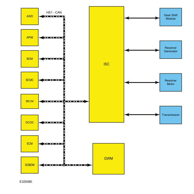
| Item | Description |
|---|---|
| 1 | BECM |
| 2 | DC/DC |
| 3 | ECM |
| 4 | BCM |
| 5 | AWD |
| 6 | GWM |
| 7 | ISC |
| 8 | APIM |
| 9 | BCMC |
| 10 | SOBDM |
| 11 | Transmission |
| 12 | Resolver Generator |
| 13 | Resolver Motor |
| 14 | Gear Shift Module |
Network Message Chart - Inverter System Controller (ISC)
| Broadcast Message | Originating Module | Message Purpose |
| ABS Active Flag | ABS | Used to determine the status of the ABS system |
| Accelerator pedal position | ECM | Accelerator pedal position used for OBDII freeze frame data |
| Air Conditioning Compressor Status | GWM | Indicates status of air conditioning compressor |
| Air Conditioning Refrigerant Pressure | ECM | Indicates status of air conditioning refrigerant pressure |
| Ambient air temperature filtered | ECM | Ambient air temperature, used to adjust high voltage battery cooling fan speed |
| Automate Parking Assist Information | PAM | Indicates status of automated parking assist information |
| Battery Voltage | BCM | Used to determine the battery voltage |
| Battery Voltage | DCDC | Used to determine the battery voltage |
| Battery Voltage | BCM | Used to determine the battery voltage |
| Battery Charge Data | SOBDM | Used to control battery charging |
| Battery State of Charge | DCDC | Used to determine the battery state of charge |
| Battery Traction Status | BECM | Used to determine the engagement of the battery to the transmission |
| Body Service Required | BCM | Used to disable the high voltage system |
| Brake Boost Data | GWM | Used to determine brake boost data |
| Brake Pedal Applied | ECM | Brake pedal position used for OBDII freeze frame data |
| Brake Sensor Status | GWM | Used to determine braking force |
| Brake Status | GWM | Used to determine brake pedal position |
| Customer Preference Settings | APIM | Used to set customer settings |
| Electric A/C Compressor | ACCM | Electric A/C compressor data |
| Engine Status | ECM | Engine data used for OBDII freeze frame data |
| Electric Park | BCMC | Electric park data |
| Engine Status | ECM | Engine data used for OBDII freeze frame data |
| Global clock data | BCM | Global clock used for OBDII freeze frame data |
| GPS Data | GPS | Used to determine location of vehicle |
| HVAC Evaporator Temperature Request | GWM | HVAC , used to indicate evaporator temperature |
| HVAC Rear Blower Status | GWM | HVAC , used to indicate passenger demands |
| Hybrid Powertrain and Battery Request | GWM | Used to request power from both electric motor and the engine |
| Hybrid Powertrain Status | GWM | Used to determine the hybrid system state |
| High Voltage Battery | BECM | Used to determine the high voltage battery information |
| Ignition Status | BCM | Current ignition state; off, accessory, run, start, unknown or invalid |
| Onboard Charging Status | GWM | Used to determine the onboard charging status |
| Odometer Master Value | ICM | Vehicle odometer value |
| Parking Aid Data | GWM | Parking Aid Sensors |
| PATS Control Command | BCM | Used to determine correct ID for vehicle starting |
| PATS Control Command | GWM | Used to determine correct ID for vehicle starting |
| Power Distribution Data | BCMC | Provides vehicle mode operation to driver |
| Powertrain Status | ECM | Provides vehicle mode operation to Inverter System Controller (ISC) |
| Regenerative Braking Information | ABS | Provides date for the regenerative braking system |
| Restraint impact event status | GWM | Used to disable the high voltage system during a crash |
| Steering Position Status | ABS | Used to determine the steering position status |
| TCU Activation Request | GWM | The TCU is requesting data from the Ford Pass Smartphone App |
| TCU Activation Status | GWM | Provides battery status to the TCU for the Ford Pass Smartphone App |
| Throttle Position Status | ECM | Used to determine the throttle position status |
| Wheel Torque Data | ABS | Used to determine torque request by driver |
| Transmission gear request | GWM | Used to determine transmission gear state |
| Wheel Data | ABS | Used to determine wheel data |
Engine Starting
Driver Demand
- The driver has changed one of the controls in the vehicle.
- The driver expects a reaction out of the vehicle. Example: Driver pressed down on accelerate pedal, air conditioning is requested on or off, and so forth.
Non-Driver Demand
- State of charge of HV battery is too low or too high.
- Air conditioning power levels to maintain core temperature.
Modes of Operation
Creep
The hybrid electric system delivers torque to the wheels to mimic the creep mode normally found on vehicles equipped with an automatic transmission. The Inverter System Controller (ISC), also known as the SOBDMC , commands a predetermined amount of torque to be delivered to the output shafts of the electronically controlled transmission. This torque is delivered from the combination of the internal combustion engine, the traction motor, or the generator motor. The maximum creep speed in forward or reverse direction is about 6 km/h (4 mph). The creep speed may vary slightly if ambient temperature, altitude, relative humidity, engine temperature, or weight of the vehicle changes.
Electric
The system operates in this mode when the vehicle is propelled by the electrical power stored in the high voltage battery. The torque is supplied to the output shafts by the electric motor. This is the preferred mode whenever the desired torque is low and can be produced more efficiently by the electrical system than the engine.
- Drive - The electric motor drives transmission providing torque to wheels meeting driver demand.
- Driven -The transmission is driven by inertia of vehicle and provides regenerative energy to electric motor meeting all or a portion of the braking demand.
Engine Cranking
The generator motor provides the engine cranking function to start or restart the internal combustion engine. When the PCM requests the engine cranking mode, the generator motor rapidly accelerates the engine speed up to about 950 RPM in about 0.3 seconds. When the engine speed reaches a calibrated speed the PCM commands the delivery of fuel and spark at the appropriate time.
Hybrid
The system operates in this mode when the engine is running and powering the electric motor which produces the electricity. The electricity produced by the electric motor charges the high voltage battery. In this mode the electric motor can operate as a motor or as a generator to make up the difference between engine torque and desired torque at the wheels. This mode is preferred whenever the electric battery needs to be charged or at moderate loads at low speeds.
- Drive - The engine drives the transmission providing torque to the wheels meeting driver demand. Requested torque above this demand is used to charge high voltage battery through the electric motor. Electric motor can also assist engine.
- Driven - The transmission is driven by inertia of vehicle and provides regenerative energy to electric motor meeting all or a portion of the braking demand. Engine can provide compression braking.
Series
The system operates in this mode when the engine is running and the vehicle is not moving. This is the preferred mode whenever the high voltage traction battery is charging, passenger compartment temperature control, high voltage traction battery temperature control or catalyst warm up is necessary.
Positive Split
The system operates in this mode when the engine is running and powering the generator motor which produces the electricity. The power from the engine is split between the path through the generator motor and the path to the output shafts of the vehicle. The electricity produced by the generator motor charges the high voltage traction battery or powers the traction motor. In this mode the traction motor can operate as a motor or as a generator to make up the difference between engine torque and desired torque at the wheels. This mode is preferred whenever the traction battery needs to be charged or at moderate loads at low speeds.
Negative Split
The system operates in this mode when the engine is running but the generator motor is reducing the engine speed. This mode occurs if the engine is running, the vehicle speed is high and the high voltage traction battery is charged.
Regenerative Braking
The regenerative braking is a software strategy and is controlled by the ABS module, the Inverter System Controller (ISC) and the BECM . Regenerative braking is the ability to capture and store a portion of the energy that would be lost as heat during a braking event. When the driver applies the brakes, the Inverter System Controller (ISC) determines how much negative torque (braking force) the electric motor should provide in addition to the friction brakes. Depending on the high voltage battery state of charge, the amount of negative torque provided by electric motor can vary between 0 and 100 percent. The electric motor then becomes a generator, which causes the energy to flow into the high voltage battery. The Inverter System Controller (ISC) strategy smoothly blends regenerative and friction brake effort to make the dual brake operation transparent to the driver.
Limited Operating Strategy (LOS) Mode
The Inverter System Controller (ISC) may initiate one or more of the LOS modes for some hybrid electric system concerns. The objective of the LOS modes are to manage vehicle operation after one or more of the following systems are disabled due to a concern:
- engine
- electric motor
- generator
- high voltage traction battery
- regenerative brake system
- transmission
Power Down Sequence
The Inverter System Controller (ISC) must conduct a normal power down sequence. Whenever the ignition is turned to the OFF or ACC position, modules powered up by the ISP-R circuit immediately shut down. However the ECM , Inverter System Controller (ISC) , and the BECM stay on, until the power down sequence is complete. The ECM and Inverter System Controller (ISC) stay powered by controlling their own dedicated power relays. The BECM is powered directly from the low voltage battery which permits wake-up function when the vehicle is off. During the power down sequence the Inverter System Controller (ISC):
- requests the ECM to cut power to the injectors and ignition coils (engine shut down)
- disables the high voltage inverters
- requests the BECM to disable the DCDC converter
- requests the BECM to open the high voltage contactors
- discharges the high voltage inverter capacitors
- opens the Inverter System Controller (ISC) power relay
If the power down sequence does not execute correctly, it is considered an abnormal shut down which may result in the ECM , the Inverter System Controller (ISC) and the BECM storing DTC s.
Power Up Sequence
The Inverter System Controller (ISC) conducts a power up sequence every time the ignition is turned from the OFF to the START position, if the gear selector is in PARK or NEUTRAL. During the power up sequence the Inverter System Controller (ISC):
- initializes and begins CAN communications with the BECM
- requests the BECM to close the high voltage contactors
- illuminates the green ready indicator indicating the vehicle is ready to drive in electric, gasoline, or a combination of electric and gasoline modes
- if required, the Inverter System Controller (ISC) will start the internal combustion engine. The internal combustion engine will not start if the gear selector is in NEUTRAL. The internal combustion engine starts if it is required for cabin heating, windshield defrost or the outside temperatures are low. The internal combustion engine also starts if the high voltage battery charge is low.
If a concern is detected during the power up sequence, the Inverter System Controller (ISC) may initiate LOS mode and store a DTC .
Component Description
Inverter System Controller (ISC)
The Inverter System Controller (ISC) is a stand alone module. The Inverter System Controller (ISC) receives a variety of CAN messages and hardwired signals from modules connected to the CAN . Based on information received, the Inverter System Controller (ISC) makes a decision on how to control the operation of the electric motor. In case of a concern, the Inverter System Controller (ISC) is able to detect and store the appropriate DTC . The Diagnostic Trouble Codes can be retrieved from the Inverter System Controller (ISC) by carrying out an on demand or continuous memory self test. The Inverter System Controller (ISC) can be reprogrammed.
 Description and Operation - Electric Powertrain Control - Overview
Overview
The
center of the electric motor control system is a microprocessor called
the Inverter System Controller (ISC), also known as the SOBDMC
...
 Diagnosis and Testing - Electric Powertrain Control
Diagnostic Trouble Code (DTC) Chart
Diagnostics in this manual assume a certain skill level and knowledge of Ford-specific diagnostic practices. SGM
REFER to: Diagnostic Methods (100-00 General Information, Description and Operation)...
Other information:
Ford Escape 2020-2026 Service Manual: Removal and Installation - High Voltage Battery Cover - Plug-In Hybrid Electric Vehicle (PHEV)
Special Tool(s) / General Equipment Power Caulk Gun Power Fixed Glass Removal Tool Vacuum Cleaner Materials Name Specification Motorcraft® High Performance Engine RTV SiliconeTA-357 WSE-M4G323-A6 Sika® SikaTack® MACH 60 / Sika® SikaTack® MACH 30 / Dow® BETASEAL™ Express - Sika® Aktivator PRO / Dow® BETAPRIME™ 5504G / Sika® Primer..
Ford Escape 2020-2026 Service Manual: Description and Operation - Blind Spot Information System - Component Location
Component Location - Blind Spot Monitoring System Item Description 1 PDM (if equipped) 2 RH exterior mirror 3 SODR 4 SODL 5 DDM (if equipped) 6 LH exterior mirror ..
Categories
- Manuals Home
- 4th Generation Ford Escape Owners Manual
- 4th Generation Ford Escape Service Manual
- Description and Operation - Identification Codes
- General Procedures - Transmission Fluid Level Check
- Switching the Rear Window Wiper On and Off. Reverse Wipe
- New on site
- Most important about car
Fastening the Seatbelts
