Ford Escape Manuals
Ford Escape 2020-2024 Service Manual / Powertrain / Engine / Electric Powertrain Control / Diagnosis and Testing - Electric Powertrain Control

Ford Escape: Electric Powertrain Control / Diagnosis and Testing - Electric Powertrain Control

Diagnostic Trouble Code (DTC) Chart

Diagnostics in this manual assume a certain skill level and knowledge of Ford-specific diagnostic practices. SGM
REFER to: Diagnostic Methods (100-00 General Information, Description and Operation).


Module DTC Description Action
APIM U0293:00 Lost Communication With Hybrid/EV Powertrain Control Module 'A': No Sub Type Information GO to Pinpoint Test BU
BCM U0293:00 Lost Communication With Hybrid/EV Powertrain Control Module 'A': No Sub Type Information GO to Pinpoint Test BU
BCMC U0293:00 Lost Communication With Hybrid/EV Powertrain Control Module 'A': No Sub Type Information GO to Pinpoint Test BU
BECM U0293:00 Lost Communication With Hybrid/EV Powertrain Control Module 'A': No Sub Type Information GO to Pinpoint Test BU
DCDC U0293:00 Lost Communication With Hybrid/EV Powertrain Control Module 'A': No Sub Type Information GO to Pinpoint Test BU
IPC U0293:00 Lost Communication With Hybrid/EV Powertrain Control Module 'A': No Sub Type Information GO to Pinpoint Test BU
PAM U0293:00 Lost Communication With Hybrid/EV Powertrain Control Module 'A': No Sub Type Information GO to Pinpoint Test BU
PCM U0293:00 Lost Communication With Hybrid/EV Powertrain Control Module 'A': No Sub Type Information GO to Pinpoint Test BU
SOBDMC C0030:00 Left Front Tone Wheel: No Sub Type Information GO to Pinpoint Test BO
SOBDMC C0033:00 Right Front Tone Wheel: No Sub Type Information GO to Pinpoint Test BO
SOBDMC C0036:00 Left Rear Tone Wheel: No Sub Type Information GO to Pinpoint Test BO
SOBDMC C0039:00 Right Rear Tone Wheel: No Sub Type Information GO to Pinpoint Test BO
SOBDMC C0049:00 Brake Fluid Level: No Sub Type Information GO to Pinpoint Test BO
SOBDMC C004B:00 Brake Fluid Level Sensor/Switch 'A' Circuit/Open: No Sub Type Information GO to Pinpoint Test BO
SOBDMC C004C:00 Brake Booster Motor 'A' Position Sensor Exceeded Learning Limit: No Sub Type Information GO to Pinpoint Test BO
SOBDMC C004E:00 Brake System Pressure Control Valve Actuator Stuck: No Sub Type Information GO to Pinpoint Test BO
SOBDMC C004F:00 ABS Control Module Over Temperature: No Sub Type Information GO to Pinpoint Test BO
SOBDMC C0061:00 Lateral Acceleration Sensor: No Sub Type Information GO to Pinpoint Test BO
SOBDMC C0062:00 Longitudinal Acceleration Sensor: No Sub Type Information GO to Pinpoint Test BO
SOBDMC C0500:00 Left Front Wheel Speed Sensor 'A' Circuit/Open: No Sub Type Information GO to Pinpoint Test BO
SOBDMC C0501:00 Left Front Wheel Speed Sensor 'A' Range/Performance: No Sub Type Information GO to Pinpoint Test BO
SOBDMC C0504:00 Left Front Wheel Speed Sensor 'A' Intermittent/Erratic: No Sub Type Information GO to Pinpoint Test BO
SOBDMC C0506:00 Right Front Wheel Speed Sensor 'A' Circuit/Open: No Sub Type Information GO to Pinpoint Test BO
SOBDMC C0507:00 Right Front Wheel Speed Sensor 'A' Range/Performance: No Sub Type Information GO to Pinpoint Test BO
SOBDMC C050A:00 Right Front Wheel Speed Sensor 'A' Intermittent/Erratic: No Sub Type Information GO to Pinpoint Test BO
SOBDMC C050C:00 Left Rear Wheel Speed Sensor 'A' Circuit/Open: No Sub Type Information GO to Pinpoint Test BO
SOBDMC C050D:00 Left Rear Wheel Speed Sensor 'A' Range/Performance: No Sub Type Information GO to Pinpoint Test BO
SOBDMC C0510:00 Left Rear Wheel Speed Sensor 'A' Intermittent/Erratic: No Sub Type Information GO to Pinpoint Test BO
SOBDMC C0512:00 Right Rear Wheel Speed Sensor 'A' Circuit/Open: No Sub Type Information GO to Pinpoint Test BO
SOBDMC C0513:00 Right Rear Wheel Speed Sensor 'A' Range/Performance: No Sub Type Information GO to Pinpoint Test BO
SOBDMC C0516:00 Right Rear Wheel Speed Sensor 'A' Intermittent/Erratic: No Sub Type Information GO to Pinpoint Test BO
SOBDMC C0518:00 Left Front Wheel Speed Sensor - Mechanical: No Sub Type Information GO to Pinpoint Test BO
SOBDMC C0519:00 Right Front Wheel Speed Sensor - Mechanical: No Sub Type Information GO to Pinpoint Test BO
SOBDMC C051A:00 Left Rear Wheel Speed Sensor - Mechanical: No Sub Type Information GO to Pinpoint Test BO
SOBDMC C051B:00 Right Rear Wheel Speed Sensor - Mechanical: No Sub Type Information GO to Pinpoint Test BO
SOBDMC C052B:00 ABS Pump Motor Control Range/Performance: No Sub Type Information GO to Pinpoint Test BO
SOBDMC C052D:00 ABS Pump Motor Control Circuit High: No Sub Type Information GO to Pinpoint Test BO
SOBDMC C052E:00 ABS Pump Motor Control Circuit Low: No Sub Type Information GO to Pinpoint Test BO
SOBDMC C053D:00 Brake Pressure Sensor 'A' Range/Performance: No Sub Type Information GO to Pinpoint Test BO
SOBDMC C0555:00 Left Front Wheel Speed Sensor 'A' Incorrect Component Installed: No Sub Type Information GO to Pinpoint Test BO
SOBDMC C0556:00 Right Front Wheel Speed Sensor 'A' Incorrect Component Installed: No Sub Type Information GO to Pinpoint Test BO
SOBDMC C0557:00 Left Rear Wheel Speed Sensor 'A' Incorrect Component Installed: No Sub Type Information GO to Pinpoint Test BO
SOBDMC C0558:00 Right Rear Wheel Speed Sensor 'A' Incorrect Component Installed: No Sub Type Information GO to Pinpoint Test BO
SOBDMC C055C:00 ABS Pump Motor Supply Voltage Circuit 'A' Range/Performance: No Sub Type Information GO to Pinpoint Test BO
SOBDMC C055E:00 Brake Hydraulic Circuit 'A' Leak: No Sub Type Information GO to Pinpoint Test BO
SOBDMC C0560:00 Brake Pressure Sensor 'A' Missing Calibration: No Sub Type Information GO to Pinpoint Test BO
SOBDMC C0563:00 ABS Control Module Performance: No Sub Type Information GO to Pinpoint Test BO
SOBDMC C0564:00 ABS Control Module System Voltage Low: No Sub Type Information GO to Pinpoint Test BO
SOBDMC C0565:00 ABS Control Module System Voltage High: No Sub Type Information GO to Pinpoint Test BO
SOBDMC C056A:00 Brake Booster Pressure Sensor Power Supply Circuit: No Sub Type Information GO to Pinpoint Test BO
SOBDMC C056B:00 Brake Pressure Sensor 'A' Intermittent/Erratic: No Sub Type Information GO to Pinpoint Test BO
SOBDMC C0594:00 Brake Booster Motor 'A' Performance: No Sub Type Information GO to Pinpoint Test BO
SOBDMC C0596:00 Brake Booster Motor 'A' Current Sensor Circuit Range/Performance: No Sub Type Information GO to Pinpoint Test BO
SOBDMC C0597:00 Brake System Control Module 'A' Performance: No Sub Type Information GO to Pinpoint Test BO
SOBDMC C1013:00 Brake System Pressure: No Sub Type Information GO to Pinpoint Test BO
SOBDMC C101F:00 Generic Valve Failure: No Sub Type Information GO to Pinpoint Test BO
SOBDMC C113A:62 Wakeup Control: Signal Compare Failure GO to Pinpoint Test A
SOBDMC P0560:00 System Voltage: No Sub Type Information GO to Pinpoint Test BQ
SOBDMC P0562:00 System Voltage Low: No Sub Type Information GO to Pinpoint Test BR
SOBDMC P0563:00 System Voltage High: No Sub Type Information GO to Pinpoint Test C
SOBDMC P0600:49 Serial Communication Link: Internal Electronic Failure GO to Pinpoint Test D
SOBDMC P0600:88 Serial Communication Link: Bus Off GO to Pinpoint Test D
SOBDMC P060A:44 Internal Control Module Monitoring Processor Performance: Data Memory Failure GO to Pinpoint Test E
SOBDMC P060A:47 Internal Control Module Monitoring Processor Performance: Watchdog/Safety µC Failure GO to Pinpoint Test E
SOBDMC P060A:86 Internal Control Module Monitoring Processor Performance: Signal Invalid GO to Pinpoint Test D
SOBDMC P060A:88 Internal Control Module Monitoring Processor Performance: Bus Off GO to Pinpoint Test D
SOBDMC P060B:47 Internal Control Module A/D Processing Performance: Watchdog/Safety µC Failure GO to Pinpoint Test F
SOBDMC P060B:62 Internal Control Module A/D Processing Performance: Signal Compare Failure GO to Pinpoint Test F
SOBDMC P060C:41 Internal Control Module Main Processor Performance: General Checksum Failure GO to Pinpoint Test G
SOBDMC P060C:42 Internal Control Module Main Processor Performance: General Memory Failure GO to Pinpoint Test G
SOBDMC P060C:44 Internal Control Module Main Processor Performance: Data Memory Failure GO to Pinpoint Test G
SOBDMC P060C:47 Internal Control Module Main Processor Performance: Watchdog/Safety µC Failure GO to Pinpoint Test G
SOBDMC P0613:86 TCM Processor: Signal Invalid GO to Pinpoint Test H
SOBDMC P0613:92 TCM Processor: Performance Or Incorrect Operation GO to Pinpoint Test H
SOBDMC P061A:92 Internal Control Module Torque Performance: Performance Or Incorrect Operation GO to Pinpoint Test BS
SOBDMC P061A:93 Internal Control Module Torque Performance: No Operation GO to Pinpoint Test BS
SOBDMC P061B:64 Internal Control Module Torque Calculation Performance: Signal Plausibility Failure GO to Pinpoint Test BS
SOBDMC P064F:00 Unauthorized Software/Calibration Detected: No Sub Type Information GO to Pinpoint Test I
SOBDMC P06A6:00 Sensor Reference Voltage 'A' Circuit Range/Performance: No Sub Type Information GO to Pinpoint Test B
SOBDMC P06A7:00 Sensor Reference Voltage 'B' Circuit Range/Performance: No Sub Type Information GO to Pinpoint Test B
SOBDMC P06A8:00 Sensor Reference Voltage 'C' Circuit Range/Performance: No Sub Type Information GO to Pinpoint Test B
SOBDMC P06A9:00 Sensor Reference Voltage 'D' Circuit Range/Performance: No Sub Type Information GO to Pinpoint Test B
SOBDMC P06B1:00 Sensor Power Supply 'A' Circuit Low: No Sub Type Information GO to Pinpoint Test B
SOBDMC P06B8:00 Internal Control Module Non-Volatile Random Access Memory (NVRAM) Error: No Sub Type Information GO to Pinpoint Test J
SOBDMC P071A:1F Transmission Mode Switch 'A' Circuit: Circuit Intermittent GO to Pinpoint Test BV
SOBDMC P071B:00 Transmission Mode Switch 'A' Circuit Low: No Sub Type Information GO to Pinpoint Test BV
SOBDMC P071C:00 Transmission Mode Switch 'A' Circuit High: No Sub Type Information GO to Pinpoint Test BV
SOBDMC P0726:62 Engine Speed Input Circuit Range/Performance: Signal Compare Failure GO to Pinpoint Test BW
SOBDMC P0811:00 Excessive Clutch 'A' Slippage: No Sub Type Information GO to Pinpoint Test CT
SOBDMC P0886:00 TCM Power Relay Control Circuit Low: No Sub Type Information GO to Pinpoint Test K
SOBDMC P0887:00 TCM Power Relay Control Circuit High: No Sub Type Information GO to Pinpoint Test K
SOBDMC P088E:00 Planetary Gear Set Failure: No Sub Type Information GO to Pinpoint Test BX
SOBDMC P0A0A:13 High Voltage System Interlock Circuit 'A': Circuit Open GO to Pinpoint Test BT
SOBDMC P0A11:00 DC/DC Converter Enable Circuit/Open: No Sub Type Information GO to Pinpoint Test CM
SOBDMC P0A18:00 Motor Torque Sensor Circuit Range/Performance: No Sub Type Information GO to Pinpoint Test B
SOBDMC P0A1A:06 Generator Control Module: Algorithm Based Failures GO to Pinpoint Test L
SOBDMC P0A1B:06 Drive Motor 'A' Control Module Performance: Algorithm Based Failures GO to Pinpoint Test BS
SOBDMC P0A1D:08 Hybrid/EV Powertrain Control Module 'A': Bus Signal/Message Failures GO to Pinpoint Test M
SOBDMC P0A23:00 Generator Torque Sensor Circuit Range/Performance: No Sub Type Information GO to Pinpoint Test B
SOBDMC P0A2B:64 Drive Motor 'A' Temperature Sensor 'A' Circuit Range/Performance: Signal Plausibility Failure GO to Pinpoint Test BY
SOBDMC P0A2C:00 Drive Motor 'A' Temperature Sensor 'A' Circuit Low: No Sub Type Information GO to Pinpoint Test BY
SOBDMC P0A2D:00 Drive Motor 'A' Temperature Sensor 'A' Circuit High: No Sub Type Information GO to Pinpoint Test BY
SOBDMC P0A2F:94 Drive Motor 'A' Over Temperature: Unexpected Operation GO to Pinpoint Test N
SOBDMC P0A37:64 Generator Temperature Sensor Circuit Range/Performance: Signal Plausibility Failure GO to Pinpoint Test O
SOBDMC P0A38:00 Generator Temperature Sensor Circuit Low: No Sub Type Information GO to Pinpoint Test O
SOBDMC P0A39:00 Generator Temperature Sensor Circuit High: No Sub Type Information GO to Pinpoint Test O
SOBDMC P0A3C:94 Drive Motor 'A' Inverter Over Temperature: Unexpected Operation GO to Pinpoint Test P
SOBDMC P0A3F:00 Drive Motor 'A' Position Sensor Circuit: No Sub Type Information GO to Pinpoint Test BZ
SOBDMC P0A40:00 Drive Motor 'A' Position Sensor Circuit Range/Performance: No Sub Type Information GO to Pinpoint Test R
SOBDMC P0A44:92 Drive Motor 'A' Position Sensor Circuit Overspeed: Performance Or Incorrect Operation GO to Pinpoint Test CA
SOBDMC P0A45:00 Drive Motor 'B' Position Sensor Circuit: No Sub Type Information GO to Pinpoint Test Q
SOBDMC P0A4C:00 Generator Position Sensor Circuit Range/Performance: No Sub Type Information GO to Pinpoint Test R
SOBDMC P0A50:92 Generator Position Sensor Circuit Overspeed: Performance Or Incorrect Operation GO to Pinpoint Test S
SOBDMC P0A5D:00 Drive Motor 'A' Phase U Current: No Sub Type Information GO to Pinpoint Test CB
SOBDMC P0A5F:00 Drive Motor 'A' Phase U Current High: No Sub Type Information GO to Pinpoint Test CC
SOBDMC P0A60:00 Drive Motor 'A' Phase V Current: No Sub Type Information GO to Pinpoint Test CB
SOBDMC P0A62:00 Drive Motor 'A' Phase V Current High: No Sub Type Information GO to Pinpoint Test CC
SOBDMC P0A63:00 Drive Motor 'A' Phase W Current: No Sub Type Information GO to Pinpoint Test CB
SOBDMC P0A65:00 Drive Motor 'A' Phase W Current High: No Sub Type Information GO to Pinpoint Test CC
SOBDMC P0A6F:00 Generator Phase U Current: No Sub Type Information GO to Pinpoint Test CB
SOBDMC P0A71:00 Generator Phase U Current High: No Sub Type Information GO to Pinpoint Test T
SOBDMC P0A72:00 Generator Phase V Current: No Sub Type Information GO to Pinpoint Test CB
SOBDMC P0A74:00 Generator Phase V Current High: No Sub Type Information GO to Pinpoint Test T
SOBDMC P0A75:00 Generator Phase W Current: No Sub Type Information GO to Pinpoint Test CB
SOBDMC P0A77:00 Generator Phase W Current High: No Sub Type Information GO to Pinpoint Test T
SOBDMC P0A78:96 Drive Motor 'A' Inverter Performance: Component Internal Failure GO to Pinpoint Test U
SOBDMC P0A7A:96 Generator Inverter Performance: Component Internal Failure GO to Pinpoint Test U
SOBDMC P0A7D:00 Hybrid/EV Battery Pack State of Charge Low: No Sub Type Information GO to Pinpoint Test CD
SOBDMC P0A94:00 DC/DC Converter 'A' Performance: No Sub Type Information GO to Pinpoint Test CE
SOBDMC P0AEE:00 Drive Motor Inverter Temperature Sensor 'A' Circuit Range/Performance: No Sub Type Information GO to Pinpoint Test W
SOBDMC P0AEF:00 Drive Motor Inverter Temperature Sensor 'A' Circuit Low: No Sub Type Information GO to Pinpoint Test W
SOBDMC P0BCD:00 Generator Inverter Temperature Sensor 'A' Circuit Range/Performance: No Sub Type Information GO to Pinpoint Test V
SOBDMC P0BCE:00 Generator Inverter Temperature Sensor 'A' Circuit Low: No Sub Type Information GO to Pinpoint Test W
SOBDMC P0BFD:00 Drive Motor 'A' Phase U-V-W Current Sensor Correlation: No Sub Type Information GO to Pinpoint Test AH
SOBDMC P0C00:00 Drive Motor 'A' Current Low: No Sub Type Information GO to Pinpoint Test CF
SOBDMC P0C03:00 Drive Motor 'B' Current Low: No Sub Type Information GO to Pinpoint Test X
SOBDMC P0C17:00 Drive Motor 'A' Position Sensor Not Learned: No Sub Type Information GO to Pinpoint Test AI
SOBDMC P0C19:00 Drive Motor 'A' Torque Delivered Performance: No Sub Type Information GO to Pinpoint Test CG
SOBDMC P0C2F:71 Internal Control Module Drive Motor/Generator-Engine Speed Sensor Performance: Actuator Stuck GO to Pinpoint Test BX
SOBDMC P0C2F:92 Internal Control Module Drive Motor/Generator-Engine Speed Sensor Performance: Performance Or Incorrect Operation GO to Pinpoint Test Y
SOBDMC P0C2F:93 Internal Control Module Drive Motor/Generator-Engine Speed Sensor Performance: No Operation GO to Pinpoint Test Y
SOBDMC P0C39:00 DC/DC Converter Temperature Sensor 'A' Circuit Range/Performance: No Sub Type Information GO to Pinpoint Test W
SOBDMC P0C3B:00 DC/DC Converter Temperature Sensor 'A' Circuit High: No Sub Type Information GO to Pinpoint Test W
SOBDMC P0C3E:00 DC/DC Converter Temperature Sensor 'B' Circuit Range/Performance: No Sub Type Information GO to Pinpoint Test W
SOBDMC P0C40:00 DC/DC Converter Temperature Sensor 'B' Circuit High: No Sub Type Information GO to Pinpoint Test W
SOBDMC P0C50:00 Drive Motor 'A' Position Sensor Circuit 'A': No Sub Type Information GO to Pinpoint Test BZ
SOBDMC P0C51:00 Drive Motor 'A' Position Sensor Circuit 'A' Range/Performance: No Sub Type Information GO to Pinpoint Test Z
SOBDMC P0C52:00 Drive Motor 'A' Position Sensor Circuit 'A' Low: No Sub Type Information GO to Pinpoint Test CH
SOBDMC P0C53:00 Drive Motor 'A' Position Sensor Circuit 'A' High: No Sub Type Information GO to Pinpoint Test CI
SOBDMC P0C55:00 Drive Motor 'A' Position Sensor Circuit 'B': No Sub Type Information GO to Pinpoint Test CJ
SOBDMC P0C57:00 Drive Motor 'A' Position Sensor Circuit 'B' Low: No Sub Type Information GO to Pinpoint Test CK
SOBDMC P0C58:00 Drive Motor 'A' Position Sensor Circuit 'B' High: No Sub Type Information GO to Pinpoint Test CL
SOBDMC P0C5F:00 Drive Motor 'B' Position Sensor Circuit 'B': No Sub Type Information GO to Pinpoint Test AA
SOBDMC P0C64:00 Generator Position Sensor Circuit A: No Sub Type Information GO to Pinpoint Test Q
SOBDMC P0C65:00 Generator Position Sensor Circuit 'A' Range/Performance: No Sub Type Information GO to Pinpoint Test Z
SOBDMC P0C66:00 Generator Position Sensor Circuit 'A' Low: No Sub Type Information GO to Pinpoint Test AB
SOBDMC P0C67:00 Generator Position Sensor Circuit 'A' High: No Sub Type Information GO to Pinpoint Test AC
SOBDMC P0C6B:00 Generator Position Sensor Circuit 'B' Low: No Sub Type Information GO to Pinpoint Test AD
SOBDMC P0C6C:00 Generator Position Sensor Circuit 'B' High: No Sub Type Information GO to Pinpoint Test AE
SOBDMC P0C79:00 Drive Motor 'A' Inverter Voltage Too High: No Sub Type Information GO to Pinpoint Test AF
SOBDMC P0CA3:00 DC/DC Converter Step Up Voltage Performance: No Sub Type Information GO to Pinpoint Test CM
SOBDMC P0D32:00 DC/DC Converter Over Temperature: No Sub Type Information GO to Pinpoint Test N
SOBDMC P0D33:00 DC/DC Converter Current High: No Sub Type Information GO to Pinpoint Test CN
SOBDMC P0DA8:00 Hybrid/EV Battery Voltage/Drive Motor 'A' Inverter Voltage Correlation: No Sub Type Information GO to Pinpoint Test AG
SOBDMC P0DFA:00 Generator Phase U-V-W Current Sensor Correlation: No Sub Type Information GO to Pinpoint Test CU
SOBDMC P0DFC:00 Generator Position Sensor Not Learned: No Sub Type Information GO to Pinpoint Test AI
SOBDMC P0E4E:00 Engine Failed to Crank: No Sub Type Information GO to Pinpoint Test BX
SOBDMC P0E51:00 DC/DC Converter Current Sensor 'A' Circuit: No Sub Type Information GO to Pinpoint Test B
SOBDMC P0E52:00 DC/DC Converter Current Sensor 'A' Circuit Range/Performance: No Sub Type Information GO to Pinpoint Test CB
SOBDMC P0E57:00 DC/DC Converter Input Voltage Too High: No Sub Type Information GO to Pinpoint Test CO
SOBDMC P0E59:00 DC/DC Converter Temperature Sensor 'C' Circuit Range/Performance: No Sub Type Information GO to Pinpoint Test CP
SOBDMC P0E5A:00 DC/DC Converter Temperature Sensor 'C' Circuit Low: No Sub Type Information GO to Pinpoint Test CQ
SOBDMC P0E5B:00 DC/DC Converter Temperature Sensor 'C' Circuit High: No Sub Type Information GO to Pinpoint Test CQ
SOBDMC P0E71:00 Generator Torque Delivered Performance: No Sub Type Information GO to Pinpoint Test AJ
SOBDMC P0EE3:00 A/C Refrigerant Distribution Valve 'B' Control Circuit/Open: No Sub Type Information GO to Pinpoint Test CY
SOBDMC P0EE4:00 A/C Refrigerant Distribution Valve 'B' Control Circuit Low: No Sub Type Information GO to Pinpoint Test CY
SOBDMC P0EE5:00 A/C Refrigerant Distribution Valve 'B' Control Circuit High: No Sub Type Information GO to Pinpoint Test CY
SOBDMC P1635:00 Tire/Axle Out of Acceptable Range: No Sub Type Information GO to Pinpoint Test CR
SOBDMC P174E:00 Output Shaft Speed / ABS Wheel Speed Correlation: No Sub Type Information GO to Pinpoint Test CS
SOBDMC P1920:62 Engine Speed Signal: Signal Compare Failure GO to Pinpoint Test CT
SOBDMC P1A07:00 Inverter High Voltage Performance: No Sub Type Information GO to Pinpoint Test AK
SOBDMC P1A0A:02 Immediate Shutdown Signal A: General Signal Failure GO to Pinpoint Test AL
SOBDMC P1A0C:00 Hybrid Powertrain Control Module - Engine Disabled: No Sub Type Information GO to Pinpoint Test CV
SOBDMC P1A0D:62 Hybrid Powertrain Control Module - Generator Disabled: Signal Compare Failure GO to Pinpoint Test CU
SOBDMC P1A0D:64 Hybrid Powertrain Control Module - Generator Disabled: Signal Plausibility Failure GO to Pinpoint Test CU
SOBDMC P1A0D:96 Hybrid Powertrain Control Module - Generator Disabled: Component Internal Failure GO to Pinpoint Test CU
SOBDMC P1A0E:62 Hybrid Powertrain Control Module - Motor Disabled: Signal Compare Failure GO to Pinpoint Test AH
SOBDMC P1A0E:64 Hybrid Powertrain Control Module - Motor Disabled: Signal Plausibility Failure GO to Pinpoint Test AH
SOBDMC P1A0E:96 Hybrid Powertrain Control Module - Motor Disabled: Component Internal Failure GO to Pinpoint Test AH
SOBDMC P1A0F:00 Hybrid Powertrain Control Module - Vehicle Disabled: No Sub Type Information GO to Pinpoint Test CV
SOBDMC P1A10:00 Hybrid Powertrain Control Module - Battery Disabled: No Sub Type Information GO to Pinpoint Test CW
SOBDMC P1A13:00 Hybrid Powertrain Control Module - Regenerative Braking Disabled: No Sub Type Information GO to Pinpoint Test CX
SOBDMC P1A40:00 ABS Control Module Configuration Not Complete: No Sub Type Information GO to Pinpoint Test BO
SOBDMC P1A41:00 ABS Control Module Programming Error: No Sub Type Information GO to Pinpoint Test BO
SOBDMC P2531:00 Ignition Switch Run Position Circuit Low: No Sub Type Information GO to Pinpoint Test BP
SOBDMC P2533:1F Ignition Switch On/Start Position Circuit: Circuit Intermittent GO to Pinpoint Test BP
SOBDMC P2533:62 Ignition Switch On/Start Position Circuit: Signal Compare Failure GO to Pinpoint Test BP
SOBDMC P2C94:00 Hybrid/EV Battery Contactor Control Supply Circuit Low: No Sub Type Information GO to Pinpoint Test CZ
SOBDMC P2C95:00 Hybrid/EV Battery Contactor Control Supply Circuit High: No Sub Type Information GO to Pinpoint Test CZ
SOBDMC U0100:00 Lost Communication With ECM/PCM 'A': No Sub Type Information GO to Pinpoint Test AM
SOBDMC U0103:87 Lost Communication With Gear Shift Control Module A: Missing Message GO to Pinpoint Test AN
SOBDMC U010F:00 Lost Communication With Air Conditioning Control Module: No Sub Type Information GO to Pinpoint Test AO
SOBDMC U0111:00 Lost Communication With Battery Energy Control Module 'A': No Sub Type Information GO to Pinpoint Test AP
SOBDMC U0121:00 Lost Communication With Anti-Lock Brake System (ABS) Control Module 'A': No Sub Type Information GO to Pinpoint Test AQ
SOBDMC U0121:8F Lost Communication With Anti-Lock Brake System (ABS) Control Module 'A': Erratic GO to Pinpoint Test AQ
SOBDMC U0140:00 Lost Communication With Body Control Module: No Sub Type Information GO to Pinpoint Test AR
SOBDMC U0143:00 Lost Communication With Body Control Module 'C': No Sub Type Information GO to Pinpoint Test AS
SOBDMC U0151:00 Lost Communication With Restraints Control Module: No Sub Type Information GO to Pinpoint Test AT
SOBDMC U0155:00 Lost Communication With Instrument Panel Cluster (IPC) Control Module: No Sub Type Information GO to Pinpoint Test AU
SOBDMC U0159:87 Lost Communication With Parking Assist Control Module 'A': Missing Message GO to Pinpoint Test AV
SOBDMC U0164:00 Lost Communication With HVAC Control Module: No Sub Type Information GO to Pinpoint Test AW
SOBDMC U016A:00 Lost Communication With Global Positioning System Module: No Sub Type Information GO to Pinpoint Test AX
SOBDMC U0198:00 Lost Communication With Telematic Control Module 'A': No Sub Type Information GO to Pinpoint Test AY
SOBDMC U019B:00 Lost Communication With Battery Charger Control Module 'A': No Sub Type Information GO to Pinpoint Test AZ
SOBDMC U0214:00 Lost Communication With Remote Function Actuation Module: No Sub Type Information GO to Pinpoint Test BA
SOBDMC U023A:00 Lost Communication With Image Processing Module A: No Sub Type Information GO to Pinpoint Test BB
SOBDMC U0253:87 Lost Communication With Accessory Protocol Interface Module: Missing Message GO to Pinpoint Test BC
SOBDMC U0298:00 Lost Communication With DC/DC Converter Control Module 'A': No Sub Type Information GO to Pinpoint Test BD
SOBDMC U0315:00 Software Incompatibility with Anti-Lock Brake System (ABS) Control Module: No Sub Type Information GO to Pinpoint Test BO
SOBDMC U0401:00 Invalid Data Received from ECM/PCM A: No Sub Type Information GO to Pinpoint Test BE
SOBDMC U0412:00 Invalid Data Received From Battery Energy Control Module 'A': No Sub Type Information GO to Pinpoint Test BE
SOBDMC U0418:00 Invalid Data Received from Brake System Control Module 'A': No Sub Type Information GO to Pinpoint Test BE
SOBDMC U045A:56 Invalid Data Received From Parking Assist Control Module 'A': Invalid/Incompatible Configuration GO to Pinpoint Test BE
SOBDMC U049C:00 Invalid Data Received From Battery Charger Control Module 'A': No Sub Type Information GO to Pinpoint Test BE
SOBDMC U0515:82 Invalid Data Received From Remote Function Actuation Module: Alive/Sequence Counter Incorrect/Not Updated GO to Pinpoint Test BE
SOBDMC U053B:00 Invalid Data Received From Image Processing Module A: No Sub Type Information GO to Pinpoint Test BE
SOBDMC U069E:81 Lost Communication with Coolant Heater 'B': Invalid Serial Data Received GO to Pinpoint Test BF
SOBDMC U069E:87 Lost Communication with Coolant Heater 'B': Missing Message GO to Pinpoint Test BF
SOBDMC U1011:86 Invalid Internal Control Module Monitoring Data Received from ECM/PCM: Signal Invalid GO to Pinpoint Test BG
SOBDMC U1012:86 Invalid Internal Control Module Monitoring Data Received from Anti-Lock Brake System (ABS) Control Module: Signal Invalid GO to Pinpoint Test BH
SOBDMC U101E:86 Invalid Internal Control Module Monitoring Data Received from Gear Shift Module: Signal Invalid GO to Pinpoint Test BI
SOBDMC U1027:00 ABS Control Module Lost Communication With ECM/PCM 'A': No Sub Type Information GO to Pinpoint Test BO
SOBDMC U1028:00 ABS Control Module Received Invalid Data from ECM/PCM 'A': No Sub Type Information GO to Pinpoint Test BO
SOBDMC U103B:00 Invalid Internal Control Module Monitoring Data Received from Differential Control Module - Rear: No Sub Type Information GO to Pinpoint Test BJ
SOBDMC U2016:04 Control Module Main Software: System Internal Failures GO to Pinpoint Test BK
SOBDMC U2100:00 Initial Configuration Not Complete: No Sub Type Information GO to Pinpoint Test BK
SOBDMC U2101:00 Control Module Configuration Incompatible: No Sub Type Information GO to Pinpoint Test BK
SOBDMC U2200:00 Control Module Configuration Memory Corrupt: No Sub Type Information GO to Pinpoint Test BK
SOBDMC U301B:00 Control Module Wake-up Circuit 'A' Low: No Sub Type Information GO to Pinpoint Test BL
SOBDMC U351B:00 High Voltage System Interlock Circuit 'D' Low: No Sub Type Information GO to Pinpoint Test BM
SOBDMC U351F:00 High Voltage System Interlock Circuit 'E' Low: No Sub Type Information GO to Pinpoint Test BN

Pinpoint Tests


PINPOINT TEST A: C113A

NOTE: The Inverter System Controller (ISC) is referred to as the SOBDMC (Secondary On-Board Diagnostic Control Module C) in the scan tool.

Normal Operation and Fault Conditions

REFER to: Electric Powertrain Control - System Operation and Component Description (303-14D Electric Powertrain Control, Description and Operation).

DTC Fault Trigger Conditions

DTC Description Fault Trigger Condition
SOBDMC C113A:62 Wakeup Control: Signal Compare Failure This DTC sets during a BCM self-test. This DTC sets when the hardwired key run signal is received but the hardwired wake-up signal is not.

Possible Sources

  • BCM self-test
  • Wiring, terminals or connectors
  • BCM configuration
  • BCM
A1 CHECK THE BCM (BODY CONTROL MODULE) CONFIGURATION

NOTE: The Inverter System Controller (ISC) is referred to as the SOBDMC (Secondary On-Board Diagnostic Control Module C) in the scan tool.

  • CHECK the vehicle service history for recent service actions related to the BCM .
  • This DTC may set due to incomplete or incorrect PMI procedures.
  • INSTALL As-Built data from PTS following diagnostic scan tool instructions under Module Programming > As-Built.

Was the PMI successful?
Yes GO to A2
No DIAGNOSE the unsuccessful PMI .
REFER to: Body Control Module (BCM) (419-10 Multifunction Electronic Modules, Diagnosis and Testing).

A2 CHECK THE BCM (BODY CONTROL MODULE) DIAGNOSTIC TROUBLE CODES (DTCS)

NOTE: After a BCM self-test, DTC C113A:62 will set in the Inverter System Controller (ISC).

NOTE: DTC C113A-11 which sets in the BCM is different from DTC C113A-62 which sets in the Inverter System Controller (ISC).

  • Ignition ON.
  • Using a diagnostic scan tool, clear all DTC s from all modules.
  • Using a diagnostic scan tool, perform the BCM self-test.

Is DTC C113A:11 set in the BCM ?
Yes GO to A3
No The As-Built data from PTS was successfully programmed during PMI .

A3 CHECK THE ECM (ENGINE CONTROL MODULE) FOR A SHORT TO GROUND
  • Ignition OFF.
  • Disconnect ECM C1381B .
  • Ignition ON.
  • Using a diagnostic scan tool, clear the BCM DTC s.
  • Wait 10 seconds.
  • Using a diagnostic scan tool, perform the BCM self-test.

Is DTC C113A:11 set in the BCM ?
Yes GO to A4
No GO to A9

A4 CHECK THE INVERTER SYSTEM CONTROLLER (ISC) FOR A SHORT TO GROUND
  • Ignition OFF.
  • Disconnect Inverter System Controller (ISC) C199A .
  • Ignition ON.
  • Wait 10 seconds.
  • Using a diagnostic scan tool, perform the BCM self-test.

Is DTC C113A:11 set in the BCM ?
Yes GO to A5
No CHECK OASIS for any applicable service articles: TSB , GSB , SSM or FSA . If a service article exists for this concern, DISCONTINUE this test and FOLLOW the service article instructions. If no service articles address this concern,
REFER to: Powertrain Control Module (PCM) Input and Output Controls (303-14C Electronic Engine Controls, Diagnosis and Testing).
Pinpoint Test Z.

A5 CHECK THE WAKE-UP SIGNAL CIRCUITS FOR A SHORT TO GROUND
  • Ignition OFF.
  • Disconnect BCM C2280E .
  • Measure:
    Positive Lead Measurement / Action Negative Lead
      C1381B-21   Ground
      C199A-13   Ground

Are the resistances greater than 10,000 ohms?
Yes GO to A6
No REPAIR the circuit.

A6 CHECK THE WAKE-UP SIGNAL CIRCUITS FOR A SHORT TO VOLTAGE
  • Ignition ON.
  • Measure:
    Positive Lead Measurement / Action Negative Lead
      C1381B-21   Ground
      C199A-13   Ground

Is any voltage present?
Yes GO to A7
No REPAIR the circuit.

A7 CHECK THE WAKE-UP SIGNAL CIRCUITS FOR AN OPEN
  • Ignition OFF.
  • Measure:
    Positive Lead Measurement / Action Negative Lead
      C1381B-21   C199A-3
      C199A-13   C2280E-10

Are the resistances less than 3 ohms?
Yes GO to A8
No REPAIR the circuit.

A8 CHECK FOR CORRECT BCM (BODY CONTROL MODULE) OPERATION
  • Ignition OFF.
  • Disconnect and inspect all BCM connectors.
  • Repair:
    • corrosion (install new connector or terminals – clean module pins)
    • damaged or bent pins – install new terminals/pins
    • pushed-out pins – install new pins as necessary
  • Reconnect the BCM connectors. Make sure they seat and latch correctly.
  • Operate the system and determine if the concern is still present.

Is the concern still present?
Yes CHECK OASIS for any applicable service articles: TSB , GSB , SSM or FSA . If a service article exists for this concern, DISCONTINUE this test and FOLLOW the service article instructions. If no service articles address this concern, INSTALL a new BCM .
REFER to: Body Control Module (BCM) (419-10 Multifunction Electronic Modules, Removal and Installation).
No The system is operating correctly at this time. The concern may have been caused by module connections. ADDRESS the root cause of any connector or pin issues.

A9 CHECK FOR CORRECT ECM (ENGINE CONTROL MODULE) OPERATION
  • Ignition OFF.
  • Disconnect and inspect all ECM connectors.
  • Repair:
    • corrosion (install new connector or terminals – clean module pins)
    • damaged or bent pins – install new terminals/pins
    • pushed-out pins – install new pins as necessary
  • Reconnect the ECM connectors. Make sure they seat and latch correctly.
  • Operate the system and determine if the concern is still present.

Is the concern still present?
Yes CHECK OASIS for any applicable service articles: TSB , GSB , SSM or FSA . If a service article exists for this concern, DISCONTINUE this test and FOLLOW the service article instructions. If no service articles address this concern,
   VIN required to access Guided Routine (PCM)
No The system is operating correctly at this time. The concern may have been caused by module connections. ADDRESS the root cause of any connector or pin issues.

PINPOINT TEST B: P06A6, P06A7, P06A8, P06B1, P06A9, P0A23, P0A18, P0E51

NOTE: The Inverter System Controller (ISC) is referred to as the SOBDMC (Secondary On-Board Diagnostic Control Module C) in the scan tool.

Normal Operation and Fault Conditions

REFER to: Electric Powertrain Control - System Operation and Component Description (303-14D Electric Powertrain Control, Description and Operation).

DTC Fault Trigger Conditions

DTC Description Fault Trigger Condition
SOBDMC P06A6:00 Sensor Reference Voltage 'A' Circuit Range/Performance: No Sub Type Information This DTC sets when an internal power supply failure is indicated.
SOBDMC P06A7:00 Sensor Reference Voltage 'B' Circuit Range/Performance: No Sub Type Information This DTC sets when an internal power supply failure is indicated.
SOBDMC P06A8:00 Sensor Reference Voltage 'C' Circuit Range/Performance: No Sub Type Information This DTC sets when an internal power supply failure is indicated.
SOBDMC P06B1:00 Sensor Power Supply 'A' Circuit Low: No Sub Type Information This DTC sets when an internal power supply failure is indicated.
SOBDMC P06A9:00 Sensor Reference Voltage 'D' Circuit Range/Performance: No Sub Type Information This DTC sets when the generator resolver 5 volt power supply is out of range.
SOBDMC P0A23:00 Generator Torque Sensor Circuit Range/Performance: No Sub Type Information This DTC sets when the generator current sensor is out of range.
SOBDMC P0A18:00 Motor Torque Sensor Circuit Range/Performance: No Sub Type Information This DTC sets when there is an internal issue within the Inverter System Controller (ISC)
SOBDMC P0E51:00 DC/DC Converter Current Sensor 'A' Circuit: No Sub Type Information This DTC sets if the inductor current sensor power supply is higher than a calibrated range.

Possible Sources

  • Wiring, terminals or connectors
  • Inverter System Controller (ISC) calibration
  • Inverter System Controller (ISC)
B1 CHECK FOR INVERTER SYSTEM CONTROLLER (ISC) DIAGNOSTIC TROUBLE CODES (DTCS)
  • Using a diagnostic scan tool, retrieve all Inverter System Controller (ISC) DTC s.

Are any Inverter System Controller (ISC) DTC s other than P06A6:00, P06A7:00, P06A8:00, P06B1:00, P06A9, P0A23, P0A18 or P0E51 present?
Yes DIAGNOSE all other Inverter System Controller (ISC) DTC s, REFER to the DTC chart in this section.
No For DTC P06A6:00, P06A7:00, P06A8:00, P06B1:00, P06A9, P0A23, P0A18 or P0E51 only GO to B2

B2 VERIFY THE INVERTER SYSTEM CONTROLLER (ISC) CALIBRATION LEVEL
  • Verify the Inverter System Controller (ISC) is at the latest calibration level.

Is the Inverter System Controller (ISC) at the latest calibration level?
Yes GO to B3
No UPDATE the Inverter System Controller (ISC) to the latest calibration level.

B3 CLEAR AND CHECK INVERTER SYSTEM CONTROLLER (ISC) DIAGNOSTIC TROUBLE CODES (DTCS)
  • Using a diagnostic scan tool, clear all Inverter System Controller (ISC) DTC s.
  • Using a diagnostic scan tool, retrieve all Inverter System Controller (ISC) DTC s.

Are DTC s P06A6:00, P06A7:00, P06A8:00, P06B1:00, P06A9, P0A23, P0A18 or P0E51 present?
Yes CHECK OASIS for any applicable service articles: TSB , GSB , SSM or FSA . If a service article exists for this concern, DISCONTINUE this test and FOLLOW the service article instructions. If no service articles address this concern, INSTALL a new Inverter System Controller (ISC).
REFER to: Inverter System Controller [SOBDMC] (303-14D Electric Powertrain Control, Removal and Installation).
No The system is operating correctly at this time. The DTC may have been set due to high network traffic or an intermittent fault condition.

PINPOINT TEST C: P0563

NOTE: The Inverter System Controller (ISC) is referred to as the SOBDMC (Secondary On-Board Diagnostic Control Module C) in the scan tool.

Normal Operation and Fault Conditions

REFER to: Electric Powertrain Control - System Operation and Component Description (303-14D Electric Powertrain Control, Description and Operation).

DTC Fault Trigger Conditions

DTC Description Fault Trigger Condition
SOBDMC P0563:00 System Voltage High: No Sub Type Information This DTC sets when the internal processor voltages are greater than a calibrated range.

Possible Sources

  • External excessive voltage
  • 24-volt jump start
  • Inverter System Controller (ISC)
C1 CHECK THE INVERTER SYSTEM CONTROLLER (ISC) CIRCUIT FOR VOLTAGE
  • Ignition OFF.
  • Disconnect Inverter System Controller (ISC) C199A .
  • Ignition ON.
  • Measure:
    Positive Lead Measurement / Action Negative Lead
      C199A-14   Ground

Is the voltage greater than 10.5 V?
Yes GO to C2
No DIAGNOSE the low voltage symptom.
Using a diagnostic scan tool, clear the Inverter System Controller (ISC) DTC s.

C2 CHECK THE INVERTER SYSTEM CONTROLLER (ISC) CIRCUIT FOR VOLTAGE
  • Measure:
    Positive Lead Measurement / Action Negative Lead
      C199A-14   Ground

Is the voltage less than 16V?
Yes GO to C3
No DIAGNOSE the high voltage symptom.
Using a diagnostic scan tool, clear the Inverter System Controller DTC s.

C3 CHECK FOR INVERTER SYSTEM CONTROLLER (ISC) DIAGNOSTIC TROUBLE CODES (DTCS)
  • Ignition OFF.
  • Connect Inverter System Controller (ISC) C199A .
  • Ignition ON.
  • Using a diagnostic scan tool, clear the Inverter System Controller (ISC) DTC s.
  • Allow the Inverter System Controller (ISC) to complete a normal power down sequence.
  • Using a diagnostic scan tool, perform the Inverter System Controller (ISC) self-test.

Was DTC P0563 read from the Inverter System Controller (ISC)?
Yes DTC P0563 frequently sets after the vehicle has been jump-started. A key cycle, followed by clearing DTC s is expected to clear this DTC , if the DTC continuously returns, INSTALL a new Inverter System Controller (ISC).
REFER to: Inverter System Controller [SOBDMC] (303-14D Electric Powertrain Control, Removal and Installation).
No Test is complete, no faults were found.

PINPOINT TEST D: P0600:49, P0600:88, P060A:86, P060A:88

NOTE: The Inverter System Controller (ISC) is referred to as the SOBDMC (Secondary On-Board Diagnostic Control Module C) in the scan tool.

Normal Operation and Fault Conditions

REFER to: Electric Powertrain Control - System Operation and Component Description (303-14D Electric Powertrain Control, Description and Operation).

DTC Fault Trigger Conditions

DTC Description Fault Trigger Condition
SOBDMC P0600:49 Serial Communication Link: Internal Electronic Failure This DTC sets when an internal error occurs.
SOBDMC P0600:88 Serial Communication Link: Bus Off This DTC sets when an internal error occurs.
SOBDMC P060A:86 Internal Control Module Monitoring Processor Performance: Signal Invalid This DTC sets when an internal error occurs.
SOBDMC P060A:88 Internal Control Module Monitoring Processor Performance: Bus Off This DTC sets when an internal error occurs.

Possible Sources

  • Inverter System Controller (ISC) calibration
  • Inverter System Controller (ISC)
D1 CHECK FOR INVERTER SYSTEM CONTROLLER (ISC) DIAGNOSTIC TROUBLE CODES (DTCS)
  • Using a diagnostic scan tool, perform the Inverter System Controller (ISC) self-test.

Are any Inverter System Controller (ISC) DTC s other than P0600:49, P0600:88, P060A:86 or P060A:88 present?
Yes DIAGNOSE all other Inverter System Controller (ISC) DTC s, REFER to the DTC chart in this section.
No For DTC P0600:49, P0600:88, P060A:86 or P060A:88 only GO to D2

D2 VERIFY THE INVERTER SYSTEM CONTROLLER (ISC) CALIBRATION LEVEL
  • Verify the Inverter System Controller (ISC) is at the latest calibration level.

Is the Inverter System Controller (ISC) at the latest calibration level?
Yes GO to D3
No UPDATE the Inverter System Controller (ISC) to the latest calibration level.

D3 CLEAR AND CHECK INVERTER SYSTEM CONTROLLER (ISC) DIAGNOSTIC TROUBLE CODES (DTCS)
  • Using a diagnostic scan tool, clear the Inverter System Controller (ISC) DTC s.
  • Using a diagnostic scan tool, perform the Inverter System Controller (ISC) self-test.

Are DTC s P0600:49, P0600:88, P060A:86 or P060A:88 present?
Yes CHECK OASIS for any applicable service articles: TSB , GSB , SSM or FSA . If a service article exists for this concern, DISCONTINUE this test and FOLLOW the service article instructions. If no service articles address this concern, INSTALL a new Inverter System Controller (ISC).
REFER to: Inverter System Controller [SOBDMC] (303-14D Electric Powertrain Control, Removal and Installation).
No The system is operating correctly at this time. The DTC may have been set due to high network traffic or an intermittent fault condition.

PINPOINT TEST E: P060A:44, P060A:47

NOTE: The Inverter System Controller (ISC) is referred to as the SOBDMC (Secondary On-Board Diagnostic Control Module C) in the scan tool.

Normal Operation and Fault Conditions

REFER to: Electric Powertrain Control - System Operation and Component Description (303-14D Electric Powertrain Control, Description and Operation).

DTC Fault Trigger Conditions

DTC Description Fault Trigger Condition
SOBDMC P060A:44 Internal Control Module Monitoring Processor Performance: Data Memory Failure This DTC sets when an internal error occurs.
SOBDMC P060A:47 Internal Control Module Monitoring Processor Performance: Watchdog/Safety µC Failure This DTC sets when an internal error occurs.

Possible Sources

  • Inverter System Controller (ISC) calibration
  • Inverter System Controller (ISC)
E1 CHECK FOR INVERTER SYSTEM CONTROLLER (ISC) DIAGNOSTIC TROUBLE CODES (DTCS)
  • Using a diagnostic scan tool, perform the Inverter System Controller (ISC) self-test.

Are any Inverter System Controller (ISC) DTC s other than P060A:44 or P060A:47 present?
Yes DIAGNOSE all other Inverter System Controller (ISC) DTC s, REFER to the DTC chart in this section.
No For DTC P060A:44 or P060A:47 only GO to E2

E2 VERIFY THE INVERTER SYSTEM CONTROLLER (ISC) CALIBRATION LEVEL
  • Verify the Inverter System Controller (ISC) is at the latest calibration level.

Is the Inverter System Controller (ISC) at the latest calibration level?
Yes GO to E3
No UPDATE the Inverter System Controller (ISC) to the latest calibration level.

E3 CLEAR AND CHECK THE INVERTER SYSTEM CONTROLLER (ISC) DIAGNOSTIC TROUBLE CODES (DTCS)
  • Using a diagnostic scan tool, clear the Inverter System Controller (ISC) DTC s.
  • Using a diagnostic scan tool, perform the Inverter System Controller (ISC) self-test.

Are DTC s P060A:44 or P060A:47 present in the Inverter System Controller (ISC)?
Yes CHECK OASIS for any applicable service articles: TSB , GSB , SSM or FSA . If a service article exists for this concern, DISCONTINUE this test and FOLLOW the service article instructions. If no service articles address this concern, INSTALL a new Inverter System Controller (ISC).
REFER to: Inverter System Controller [SOBDMC] (303-14D Electric Powertrain Control, Removal and Installation).
No The system is operating correctly at this time. The DTC may have been set due to high network traffic or an intermittent fault condition.

PINPOINT TEST F: P060B:47, P060B:62

NOTE: The Inverter System Controller (ISC) is referred to as the SOBDMC (Secondary On-Board Diagnostic Control Module C) in the scan tool.

Normal Operation and Fault Conditions

REFER to: Electric Powertrain Control - System Operation and Component Description (303-14D Electric Powertrain Control, Description and Operation).

DTC Fault Trigger Conditions

DTC Description Fault Trigger Condition
SOBDMC P060B:47 Internal Control Module A/D Processing Performance: Watchdog/Safety µC Failure This DTC sets when an internal error occurs.
SOBDMC P060B:62 Internal Control Module A/D Processing Performance: Signal Compare Failure This DTC sets when an internal error occurs.

Possible Sources

  • Inverter System Controller (ISC) calibration
  • Intermittent low voltage wiring concern
  • Wiring, terminals or connectors
  • Inverter System Controller (ISC)
F1 CHECK FOR INVERTER SYSTEM CONTROLLER (ISC) DIAGNOSTIC TROUBLE CODES (DTCS)
  • Using a diagnostic scan tool, perform the Inverter System Controller (ISC) self-test.

Are any Inverter System Controller (ISC) DTC s other than P060B:47 or P060B:62 present?
Yes DIAGNOSE all other Inverter System Controller (ISC) DTC s, REFER to the DTC chart in this section.
No For DTC P060B:47 or P060B:62 only GO to F2

F2 VERIFY THE INVERTER SYSTEM CONTROLLER (ISC) CALIBRATION LEVEL
  • Verify the Inverter System Controller (ISC) is at the latest calibration level.

Is the Inverter System Controller (ISC) at the latest calibration level?
Yes GO to F3
No UPDATE the Inverter System Controller (ISC) to the latest calibration level.

F3 CLEAR AND CHECK THE INVERTER SYSTEM CONTROLLER (ISC) DIAGNOSTIC TROUBLE CODES (DTCS)
  • Using a diagnostic scan tool, clear the Inverter System Controller (ISC) DTC s.
  • Using a diagnostic scan tool, perform the Inverter System Controller (ISC) self-test.

Are DTC s P060B:47 or P060B:62 present in the Inverter System Controller (ISC)?
Yes CHECK OASIS for any applicable service articles: TSB , GSB , SSM or FSA . If a service article exists for this concern, DISCONTINUE this test and FOLLOW the service article instructions. If no service articles address this concern, INSTALL a new Inverter System Controller (ISC).
REFER to: Inverter System Controller [SOBDMC] (303-14D Electric Powertrain Control, Removal and Installation).
No The system is operating correctly at this time. The DTC may have been set due to high network traffic or an intermittent fault condition.

PINPOINT TEST G: P060C:41, P060C:42, P060C:44, P060C:47

NOTE: The Inverter System Controller (ISC) is referred to as the SOBDMC (Secondary On-Board Diagnostic Control Module C) in the scan tool.

Normal Operation and Fault Conditions

REFER to: Electric Powertrain Control - System Operation and Component Description (303-14D Electric Powertrain Control, Description and Operation).

DTC Fault Trigger Conditions

DTC Description Fault Trigger Condition
SOBDMC P060C:41 Internal Control Module Main Processor Performance: General Checksum Failure This DTC sets when an internal error occurs.
SOBDMC P060C:42 Internal Control Module Main Processor Performance: General Memory Failure This DTC sets when an internal error occurs.
SOBDMC P060C:44 Internal Control Module Main Processor Performance: Data Memory Failure This DTC sets when an internal error occurs.
SOBDMC P060C:47 Internal Control Module Main Processor Performance: Watchdog/Safety µC Failure This DTC sets when an internal error occurs.

Possible Sources

  • Inverter System Controller (ISC) calibration
  • Inverter System Controller (ISC)
G1 CHECK FOR INVERTER SYSTEM CONTROLLER (ISC) DIAGNOSTIC TROUBLE CODES (DTCS)
  • Using a diagnostic scan tool, perform the Inverter System Controller (ISC) self-test.

Are any Inverter System Controller (ISC) DTC s other than P060C:41, P060C:42, P060C:44 or P060C:47 present?
Yes DIAGNOSE all other Inverter System Controller (ISC) DTC s, REFER to the DTC chart in this section.
No For DTC P060C:41, P060C:42, P060C:44 or P060C:47 only GO to G2

G2 VERIFY ALL CAN MODULE CALIBRATION LEVELS
  • Verify all CAN modules are at the latest calibration level.

Are all CAN modules are at the latest calibration level?
Yes GO to G3
No UPDATE the Inverter System Controller (ISC) to the latest calibration level.

G3 CLEAR AND CHECK THE INVERTER SYSTEM CONTROLLER (ISC) DIAGNOSTIC TROUBLE CODES (DTCS)
  • Using a diagnostic scan tool, clear the Inverter System Controller (ISC) DTC s.
  • Using a diagnostic scan tool, perform the Inverter System Controller (ISC) self-test.

Are DTC s P060C:41, P060C:42, P060C:44 or P060C:47 present in the Inverter System Controller (ISC)?
Yes CHECK OASIS for any applicable service articles: TSB , GSB , SSM or FSA . If a service article exists for this concern, DISCONTINUE this test and FOLLOW the service article instructions. If no service articles address this concern, INSTALL a new Inverter System Controller (ISC).
REFER to: Inverter System Controller [SOBDMC] (303-14D Electric Powertrain Control, Removal and Installation).
No The system is operating correctly at this time. The DTC may have been set due to high network traffic or an intermittent fault condition.

PINPOINT TEST H: P0613:86, P0613:92

NOTE: The Inverter System Controller (ISC) is referred to as the SOBDMC (Secondary On-Board Diagnostic Control Module C) in the scan tool.

Normal Operation and Fault Conditions

REFER to: Electric Powertrain Control - System Operation and Component Description (303-14D Electric Powertrain Control, Description and Operation).

DTC Fault Trigger Conditions

DTC Description Fault Trigger Condition
SOBDMC P0613:86 TCM Processor: Signal Invalid This DTC sets when an internal error occurs, or other DTC s have set.
SOBDMC P0613:92 TCM Processor: Performance Or Incorrect Operation This DTC sets when an internal error occurs, or other DTC s have set.

Possible Sources

  • Other Inverter System Controller (ISC) DTC s
  • Inverter System Controller (ISC) calibration
  • Inverter System Controller (ISC)
H1 CHECK FOR INVERTER SYSTEM CONTROLLER (ISC) DIAGNOSTIC TROUBLE CODES (DTCS)

NOTE: P0613 generally sets as a result of other DTCs which should be diagnosed first. P0613 rarely sets alone.

  • Using a diagnostic scan tool, perform the Inverter System Controller (ISC) self-test.

Are any Inverter System Controller (ISC) DTC s other than P0613:86 or P0613:92 present?
Yes DIAGNOSE all other Inverter System Controller (ISC) DTC s, REFER to the DTC chart in this section.
No For DTC P0613:86 or P0613:92 only GO to H2

H2 VERIFY THE INVERTER SYSTEM CONTROLLER (ISC) CALIBRATION LEVEL
  • Verify the Inverter System Controller (ISC) is at the latest calibration level.

Is the Inverter System Controller (ISC) at the latest calibration level?
Yes GO to H3
No UPDATE the Inverter System Controller (ISC) to the latest calibration level.

H3 CLEAR AND CHECK THE INVERTER SYSTEM CONTROLLER (ISC) DIAGNOSTIC TROUBLE CODES (DTCS)
  • Using a diagnostic scan tool, clear the Inverter System Controller (ISC) DTC s.
  • Using a diagnostic scan tool, perform the Inverter System Controller (ISC) self-test.

Is DTC P0613:86 or P0613:92 the only DTC present in the Inverter System Controller (ISC)?
Yes CHECK OASIS for any applicable service articles: TSB , GSB , SSM or FSA . If a service article exists for this concern, DISCONTINUE this test and FOLLOW the service article instructions. If no service articles address this concern and this is the only DTC present, INSTALL a new Inverter System Controller (ISC).
REFER to: Inverter System Controller [SOBDMC] (303-14D Electric Powertrain Control, Removal and Installation).
No DIAGNOSE any other remaining Inverter System Controller (ISC) DTC s.

PINPOINT TEST I: P064F

NOTE: The Inverter System Controller (ISC) is referred to as the SOBDMC (Secondary On-Board Diagnostic Control Module C) in the scan tool.

Normal Operation and Fault Conditions

REFER to: Electric Powertrain Control - System Operation and Component Description (303-14D Electric Powertrain Control, Description and Operation).

DTC Fault Trigger Conditions

DTC Description Fault Trigger Condition
SOBDMC P064F:00 Unauthorized Software/Calibration Detected: No Sub Type Information This DTC sets when the Inverter System Controller (ISC) has not been flashed with production intent software.

Possible Sources

  • Inverter System Controller (ISC) calibration
I1 REPROGRAM OR UPDATE THE CALIBRATION
  • Reprogram or update the calibration.
  • Reprogram the vehicle identification (VID) block (use as built data).

Was the programming of the Inverter System Controller (ISC) successful?
Yes GO to I2
No CHECK OASIS for any applicable service articles: TSB , GSB , SSM or FSA . If a service article exists for this concern, ENSURE the 12V Maintainer is installed on the vehicle, check CAN connections, then attempt reflash.
REFER to: Module Programming (418-01 Module Configuration, General Procedures).

I2 CLEAR AND CHECK THE INVERTER SYSTEM CONTROLLER (ISC) DIAGNOSTIC TROUBLE CODES (DTCS)
  • Using a diagnostic scan tool, clear the Inverter System Controller (ISC) DTC s.
  • Using a diagnostic scan tool, perform the Inverter System Controller (ISC) self-test.

Is DTC P064F:00 present in the Inverter System Controller (ISC)?
Yes CHECK OASIS for any applicable service articles: TSB , GSB , SSM or FSA . If a service article exists for this concern, DISCONTINUE this test and FOLLOW the service article instructions. If no service articles address this concern, it is necessary to seek additional help. REFER to the Service Repair And Technical Assistance Process. A vehicle data recorder (VDR) or similar recorder may also be useful.
No The system is operating correctly at this time. The DTC may have been set due to high network traffic or an intermittent fault condition.

PINPOINT TEST J: P06B8

NOTE: The Inverter System Controller (ISC) is referred to as the SOBDMC (Secondary On-Board Diagnostic Control Module C) in the scan tool.

Normal Operation and Fault Conditions

REFER to: Electric Powertrain Control - System Operation and Component Description (303-14D Electric Powertrain Control, Description and Operation).

DTC Fault Trigger Conditions

DTC Description Fault Trigger Condition
SOBDMC P06B8:00 Internal Control Module Non-Volatile Random Access Memory (NVRAM) Error: No Sub Type Information This DTC sets when an internal error occurs.

Possible Sources

  • Inverter System Controller (ISC) calibration
  • Inverter System Controller (ISC)
J1 VERIFY THE INVERTER SYSTEM CONTROLLER (ISC) CALIBRATION LEVEL
  • Verify the Inverter System Controller (ISC) is at the latest calibration level.

Is the Inverter System Controller (ISC) at the latest calibration level?
Yes GO to J2
No UPDATE the Inverter System Controller (ISC) to the latest calibration level.

J2 CLEAR AND CHECK THE INVERTER SYSTEM CONTROLLER (ISC) DIAGNOSTIC TROUBLE CODES (DTCS)
  • Using a diagnostic scan tool, clear the Inverter System Controller (ISC) DTC s.
  • Using a diagnostic scan tool, perform the Inverter System Controller (ISC) self-test.

Is DTC P06B8:00 present in the Inverter System Controller (ISC)?
Yes CHECK OASIS for any applicable service articles: TSB , GSB , SSM or FSA . If a service article exists for this concern, DISCONTINUE this test and FOLLOW the service article instructions. If no service articles address this concern, INSTALL a new Inverter System Controller (ISC).
REFER to: Inverter System Controller [SOBDMC] (303-14D Electric Powertrain Control, Removal and Installation).
No The system is operating correctly at this time. The DTC may have been set due to high network traffic or an intermittent fault condition.

PINPOINT TEST K: P0886, P0887

NOTE: The Inverter System Controller (ISC) is referred to as the SOBDMC (Secondary On-Board Diagnostic Control Module C) in the scan tool.

Normal Operation and Fault Conditions

REFER to: Electric Powertrain Control - System Operation and Component Description (303-14D Electric Powertrain Control, Description and Operation).

DTC Fault Trigger Conditions

DTC Description Fault Trigger Condition
SOBDMC P0886:00 TCM Power Relay Control Circuit Low: No Sub Type Information This DTC sets when a short to ground is detected on the relay control circuit.
SOBDMC P0887:00 TCM Power Relay Control Circuit High: No Sub Type Information This DTC sets when a short to power or open is detected on the relay control circuit.

Possible Sources

  • Wiring, terminals or connectors
  • BCMC concern
K1 CHECK FOR LOW VOLTAGE BECM (BATTERY ENERGY CONTROL MODULE) DIAGNOSTIC TROUBLE CODES (DTCS)

NOTE: Turn the ignition OFF for 5 minutes before carrying out the self-test or clearing DTCs.

NOTE: DTC P0887 may set as a result of a low 12 volt battery concern or loose connections to the 12V battery or ground.

NOTE: DTCs P0562 and U3003 may set in any module in addition to DTC P0887 set in the Inverter System Controller (ISC). Diagnose all other low 12V DTCs before entering this pinpoint test.

  • Ignition ON.
  • Using a diagnostic scan tool, retrieve all DTC s.

Are there any DTC s related to the 12V battery present?
Yes DIAGNOSE all 12V battery DTC s.
No GO to K2

K2 CHECK FOR LOW VOLTAGE INVERTER SYSTEM CONTROLLER (ISC) DIAGNOSTIC TROUBLE CODES (DTCS)

NOTE: The key cycle is very important, the DTC will not clear unless a key cycle is completed.

  • Ignition OFF.
  • Wait 5 minutes.
  • Ignition ON.
  • Using a diagnostic scan tool, clear the Inverter System Controller (ISC) DTC s.
  • Using a diagnostic scan tool, perform the Inverter System Controller (ISC) self-test.

Are DTC s P0886 or P0887 present in the Inverter System Controller (ISC)?
Yes GO to K3
No The system is operating correctly at this time. The DTC may have been set due to high network traffic or an intermittent fault condition.

K3 CHECK THE BATTERY AND CHARGING SYSTEM
  • Check the battery and charging system voltages.
    REFER to: Specifications (414-01 Battery, Mounting and Cables, Specifications).

Are the battery and charging system voltages within specification?
Yes GO to K4
No REPAIR as necessary.
REFER to: Battery (414-01 Battery, Mounting and Cables, Diagnosis and Testing). Clear the inverter System Controller (ISC) DTC s. REPEAT the self-test.

K4 CHECK THE TCMRC CIRCUIT FOR AN OPEN
  • Ignition OFF.
  • Disconnect Inverter System Controller (ISC) C199A .
  • Disconnect BCMC C1002 .
  • Measure:
    Positive Lead Measurement / Action Negative Lead
      C1002-9   C199A-14

Is the resistance less than 5 ohms?
Yes GO to K5
No With the aid of the wiring diagram, REPAIR the open circuit.

K5 CHECK THE TCMRC CIRCUIT FOR A SHORT TO GROUND
  • Measure:
    Positive Lead Measurement / Action Negative Lead
      C199A-14   Ground

Is the resistance greater than 10K ohms?
Yes GO to K6
No With the aid of the wiring diagram, REPAIR the short circuit.

K6 CHECK THE TCMRC CIRCUIT FOR A SHORT TO VOLTAGE
  • Ignition ON.
  • Measure:
    Positive Lead Measurement / Action Negative Lead
      C199A-14   Ground

Is any voltage present?
Yes With the aid of the wiring diagram, REPAIR the short circuit.
No GO to K7

K7 CHECK FOR CORRECT INVERTER SYSTEM CONTROLLER (ISC) OPERATION
  • Ignition OFF.
  • Disconnect and inspect all Inverter System Controller (ISC) connectors.
  • Repair:
    • corrosion (install new connector or terminals – clean module pins)
    • damaged or bent pins – install new terminals/pins
    • pushed-out pins – install new pins as necessary
  • Reconnect the Inverter System Controller (ISC) connectors. Make sure they seat and latch correctly.
  • Connect BCMC C1002 .
  • Operate the system and determine if the concern is still present.

Is the concern still present?
Yes GO to K8
No The system is operating correctly at this time. The concern may have been caused by module connections. ADDRESS the root cause of any connector or pin issues.

K8 INTERMITTENT CHECK
  • Access the  SOBDMC  and monitor the  VPWR (V)  PID

  • While observing, the PID s carry out the following:
    • Carefully wiggle all accessible wiring and connectors associated with the Inverter System Controller (ISC)
    • Wiggle the Inverter System Controller (ISC) connectors and harnesses
    • Look for sudden changes in voltage when the harness and connectors are wiggled

Are any concerns present?
Yes REPAIR as necessary. CLEAR the Inverter System Controller (ISC) DTC s. REPEAT the self-test
No GO to K9

K9 CHECK THE INVERTER SYSTEM CONTROLLER (ISC) VPWR CIRCUITS FOR AN OPEN
  • Ignition OFF.
  • Disconnect Inverter System Controller (ISC) C199A .
  • Disconnect BCMC C1002 .
  • Measure:
    Positive Lead Measurement / Action Negative Lead
      C1002-27   C199A-39
      C1002-27   C199A-40

Is the resistance less than 5 ohms?
Yes GO to K10
No With the aid of the wiring diagram, REPAIR the open circuit.

K10 CHECK THE INVERTER SYSTEM CONTROLLER (ISC) VPWR CIRCUITS FOR A SHORT TO VOLTAGE
  • Ignition ON.
  • Measure:
    Positive Lead Measurement / Action Negative Lead
      C199A-39   Ground
      C199A-40   Ground

Is any voltage present?
Yes With the aid of the wiring diagram, REPAIR the short circuit.
No GO to K11

K11 CHECK THE INVERTER SYSTEM CONTROLLER (ISC) ISP-R CIRCUIT FOR AN OPEN
  • Ignition OFF.
  • Disconnect BJB C1035A .
  • Measure:
    Positive Lead Measurement / Action Negative Lead
      C1002-2   C199A-4
      C1035A-37   C199A-4

Is the resistance less than 5 ohms?
Yes GO to K12
No With the aid of the wiring diagram, REPAIR the open circuit.

K12 CHECK THE INVERTER SYSTEM CONTROLLER (ISC) ISP-R CIRCUIT FOR A SHORT TO VOLTAGE
  • Ignition ON.
  • Measure:
    Positive Lead Measurement / Action Negative Lead
      C199A-4   Ground

Is any voltage present?
Yes With the aid of the wiring diagram, REPAIR the short circuit.
No GO to K13

K13 CHECK THE INVERTER SYSTEM CONTROLLER (ISC) ISP-R CIRCUIT FOR VOLTAGE
  • Ignition OFF.
  • Connect a 5 amp fused jumper wire between:
    Positive Lead Measurement / Action Negative Lead
      C199A-14   Ground
  • Ignition ON.
  • Measure:
    Positive Lead Measurement / Action Negative Lead
      C199A-39   Ground
      C199A-40   Ground

Are the voltages greater than 10.5 V?
Yes
REFER to: Powertrain Control Module (PCM) Input and Output Controls (303-14C Electronic Engine Controls, Diagnosis and Testing).
Pinpoint Test Z.
No INSTALL a new BCMC .
REFER to: Body Control Module C (BCMC) (419-10 Multifunction Electronic Modules, Removal and Installation).

PINPOINT TEST L: P0A1A:06

NOTE: The Inverter System Controller (ISC) is referred to as the SOBDMC (Secondary On-Board Diagnostic Control Module C) in the scan tool.

Normal Operation and Fault Conditions

REFER to: Electric Powertrain Control - System Operation and Component Description (303-14D Electric Powertrain Control, Description and Operation).

DTC Fault Trigger Conditions

DTC Description Fault Trigger Condition
SOBDMC P0A1A:06 Generator Control Module: Algorithm Based Failures This DTC sets when the generator torque exceeds the calibrated threshold.

Possible Sources

  • Inverter System Controller (ISC) calibration
  • Inverter System Controller (ISC)
L1 PERFORM THE INVERTER SYSTEM CONTROLLER (ISC) SELF-TEST

NOTE: P0A1A:06 generally sets as a result of other DTCs which should be diagnosed first. P0A1A:06 rarely sets alone.

  • Ignition ON.
  • Using a diagnostic scan tool, perform the Inverter System Controller (ISC) self-test and record any DTC s.

Are any Inverter System Controller (ISC) DTC s other than P0A1A:06 present?
Yes DIAGNOSE all other Inverter System Controller (ISC) DTC s, REFER to the DTC chart in this section.
No For DTC only GO to L2

L2 VERIFY THE INVERTER SYSTEM CONTROLLER (ISC) CALIBRATION LEVEL
  • Verify the Inverter System Controller (ISC) is at the latest calibration level.

Is the Inverter System Controller (ISC) at the latest calibration level?
Yes GO to L3
No UPDATE the Inverter System Controller (ISC) to the latest calibration level.

L3 CLEAR AND CHECK THE INVERTER SYSTEM CONTROLLER (ISC) DTCS
  • Using a diagnostic scan tool, clear the Inverter System Controller (ISC) DTC s.
  • Using a diagnostic scan tool, perform the Inverter System Controller (ISC) self-test.

Is DTC P0A1A:06 the only DTC present in the Inverter System Controller (ISC)?
Yes CHECK OASIS for any applicable service articles: TSB , GSB , SSM or FSA . If a service article exists for this concern, DISCONTINUE this test and FOLLOW the service article instructions. If no service articles address this concern, INSTALL a new Inverter System Controller (ISC).
REFER to: Inverter System Controller [SOBDMC] (303-14D Electric Powertrain Control, Removal and Installation).
No The system is operating correctly at this time. The DTC may have been set due to high network traffic or an intermittent fault condition.

PINPOINT TEST M: P0A1D:08

NOTE: The Inverter System Controller (ISC) is referred to as the SOBDMC (Secondary On-Board Diagnostic Control Module C) in the scan tool.

Normal Operation and Fault Conditions

REFER to: Electric Powertrain Control - System Operation and Component Description (303-14D Electric Powertrain Control, Description and Operation).

DTC Fault Trigger Conditions

DTC Description Fault Trigger Condition
SOBDMC P0A1D:08 Hybrid/EV Powertrain Control Module 'A': Bus Signal/Message Failures This DTC sets when a software calibration issue is detected.

Possible Sources

  • Inverter System Controller (ISC) calibration
M1 VERIFY THE INVERTER SYSTEM CONTROLLER (ISC) CALIBRATION LEVEL
  • Verify the Inverter System Controller (ISC) is at the latest calibration level.

Is the Inverter System Controller (ISC) at the latest calibration level?
Yes GO to M2
No UPDATE the Inverter System Controller (ISC) to the latest calibration level.

M2 CLEAR AND CHECK THE INVERTER SYSTEM CONTROLLER (ISC) DIAGNOSTIC TROUBLE CODES (DTCS)
  • Using a diagnostic scan tool, clear the Inverter System Controller (ISC) DTC s.
  • Using a diagnostic scan tool, perform the Inverter System Controller (ISC) self-test.

Is DTC P0A1D:08 present in the Inverter System Controller (ISC)?
Yes CHECK OASIS for any applicable service articles: TSB , GSB , SSM or FSA . If a service article exists for this concern, DISCONTINUE this test and FOLLOW the service article instructions. If no service articles address this concern, REFLASH the Inverter System Controller (ISC) with the latest calibration. If the concern still exists after the reflash, it is necessary to seek additional help. REFER to the Service Repair And Technical Assistance Process. A vehicle data recorder (VDR) or similar recorder may also be useful.
No The system is operating correctly at this time. The DTC may have been set due to high network traffic or an intermittent fault condition.

PINPOINT TEST N: P0A2F:94, P0D32

NOTE: The Inverter System Controller (ISC) is referred to as the SOBDMC (Secondary On-Board Diagnostic Control Module C) in the scan tool.

Normal Operation and Fault Conditions

REFER to: Electric Powertrain Control - System Operation and Component Description (303-14D Electric Powertrain Control, Description and Operation).

DTC Fault Trigger Conditions

DTC Description Fault Trigger Condition
SOBDMC P0A2F:94 Drive Motor 'A' Over Temperature: Unexpected Operation This DTC sets from elevated temperatures in the transmission.
SOBDMC P0D32:00 DC/DC Converter Over Temperature: No Sub Type Information This DTC sets when the inductor temperature reading is greater than the calibrated threshold.

Possible Sources

  • Wiring, terminals or connectors
  • Transmission fluid level or temperature
  • Transmission cooling system
  • Inductor
  • Transmission assembly
N1 CHECK THE INVERTER SYSTEM CONTROLLER (ISC) DIAGNOSTIC TROUBLE CODES (DTCS)
  • Ignition ON.
  • Using a diagnostic scan tool, perform the Inverter System Controller (ISC) self-test.

Is DTC P0A2F:94 or P0D32 present in the Inverter System Controller (ISC)?
Yes GO to N2
No The system is operating correctly at this time. The DTC may have been set due to high network traffic or an intermittent fault condition.

N2 CHECK THE AUTOMATIC TRANSMISSION FLUID LEVEL

NOTE: A low automatic transmission fluid level may cause a traction motor over temperature condition.

  • Verify the automatic transmission fluid level and condition is correct.
    REFER to: Transmission Fluid Level Check (307-01B Automatic Transmission - Automatic Transmission – HF45, General Procedures).

Is the transmission fluid level and condition correct?
Yes GO to N3
No DIAGNOSE the transmission cooling concern.
REFER to: Automatic Transmission (307-01B Automatic Transmission - Automatic Transmission – HF45, Diagnosis and Testing).

N3 CHECK THE TRANSMISSION TEMPERATURE SENSOR CORRELATION
  • Access the  SOBDMC  and monitor the  GCLTEMP (Deg C)  PID

  • Access the  SOBDMC  and monitor the  TFT (Deg C)  PID

  • Access the  SOBDMC  and monitor the  MCLTEMP (Deg C)  PID

  • Access the  SOBDMC  and monitor the  VVC_TEMP (Deg C)  PID

  • Road test the vehicle while monitoring the PID s.

Were any of the monitored PID s above 266 °F ( 130 °C) during the road test?
Yes DIAGNOSE the transmission cooling concern.
REFER to: Automatic Transmission (307-01B Automatic Transmission - Automatic Transmission – HF45, Diagnosis and Testing).
No GO to N4

N4 CHECK THE GENERATOR TEMPERATURE SIGNAL CIRCUIT FOR A SHORT TO GROUND
  • Ignition OFF.
  • Disconnect Transmission C1111 .
  • Measure:
    Positive Lead Measurement / Action Negative Lead
      C1111-14   Ground

Is the resistance greater than 10K ohms?
Yes GO to N5
No With the aid of the wiring diagram, REPAIR the short circuit.

N5 CHECK THE GENERATOR TEMPERATURE RETURN CIRCUIT FOR A SHORT TO GROUND
  • Measure:
    Positive Lead Measurement / Action Negative Lead
      C1111-4   Ground

Is the resistance greater than 10K ohms?
Yes GO to N6
No With the aid of the wiring diagram, REPAIR the short circuit.

N6 CHECK THE MOTOR TEMPERATURE SIGNAL CIRCUIT FOR A SHORT TO GROUND
  • Measure:
    Positive Lead Measurement / Action Negative Lead
      C1111-35   Ground

Is the resistance greater than 10K ohms?
Yes GO to N7
No With the aid of the wiring diagram, REPAIR the short circuit.

N7 CHECK THE MOTOR TEMPERATURE RETURN CIRCUIT FOR A SHORT TO GROUND
  • Measure:
    Positive Lead Measurement / Action Negative Lead
      C1111-25   Ground

Is the resistance greater than 10K ohms?
Yes GO to N8
No With the aid of the wiring diagram, REPAIR the short circuit.

N8 CHECK THE TRANSMISSION FLUID TEMPERATURE SIGNAL CIRCUIT FOR A SHORT TO GROUND
  • Disconnect Transmission Fluid Thermistor C1032 .
  • Measure:
    Positive Lead Measurement / Action Negative Lead
      C1111-34   Ground

Is the resistance greater than 10K ohms?
Yes GO to N9
No With the aid of the wiring diagram, REPAIR the short circuit.

N9 CHECK THE TRANSMISSION FLUID TEMPERATURE RETURN CIRCUIT FOR A SHORT TO GROUND
  • Measure:
    Positive Lead Measurement / Action Negative Lead
      C1111-24   Ground

Is the resistance greater than 10K ohms?
Yes GO to N10
No With the aid of the wiring diagram, REPAIR the short circuit.

N10 CHECK THE INDUCTOR SIGNAL CIRCUIT FOR A SHORT TO GROUND
  • Measure:
    Positive Lead Measurement / Action Negative Lead
      C1111-15   Ground

Is the resistance greater than 10K ohms?
Yes GO to N11
No With the aid of the wiring diagram, REPAIR the short circuit.

N11 CHECK THE INDUCTOR RETURN CIRCUIT FOR A SHORT TO GROUND
  • Measure:
    Positive Lead Measurement / Action Negative Lead
      C1111-5   Ground

Is the resistance greater than 10K ohms?
Yes GO to N12
No With the aid of the wiring diagram, REPAIR the short circuit.

N12 INTERMITTENT CHECK
  • Access the  SOBDMC  and monitor the  GCLTEMP (Deg C)  PID

  • Access the  SOBDMC  and monitor the  TFT (Deg C)  PID

  • Access the  SOBDMC  and monitor the  MCLTEMP (Deg C)  PID

  • Access the  SOBDMC  and monitor the  VVC_TEMP (Deg C)  PID

  • While observing the PID s carry out the following:
    • Lightly tap on the transmission assembly connector and wiggle the accessible harness from the transmission assembly to the Inverter System Controller (ISC)
    • Wiggle the transmission assembly connector
    • Look for sudden changes in temperature when the harness and connectors are wiggled

Are any concerns present?
Yes REPAIR as necessary. CLEAR the Inverter System Controller (ISC) DTC s. REPEAT the self-test
No GO to N13

N13 CHECK THE GENERATOR TEMPERATURE SENSOR
  • Measure and record:
    Positive Lead Measurement / Action Negative Lead
    C1111 pin 14, component side C1111 pin 4, component side
  • Record the measurement result and compare with the expected temperature values below:
    • -40 °F ( -40 °C) 1695.776 K ohms - 2302.415 K ohms
    • -31 °F ( -35 °C) 1194.043 K ohms - 1598.148 K ohms
    • -22 °F ( -30 °C) 852.9844 K ohms - 1126.096 K ohms
    • -13 °F ( -25 °C) 617.6642 K ohms - 804.7572 K ohms
    • -4 °F ( -20 °C) 453.0069 K ohms - 582.8025 K ohms
    • 5 °F ( -15 °C) 336.2607 K ohms - 427.3758 K ohms
    • 14 °F ( -10 °C) 252.446 K ohms - 317.117 K ohms
    • 23 °F ( -5 °C) 191.5609 K ohms - 237.9395 K ohms
    • 32 °F ( °C) 146.8371 K ohms - 180.419 K ohms
    • 41 °F ( 5 °C) 113.637 K ohms - 138.172 K ohms
    • 50 °F ( 10 °C) 88.743 K ohms - 106.82 K ohms
    • 59 °F ( 15 °C) 69.9003 K ohms - 83.3236 K ohms
    • 68 °F ( 20 °C) 55.5087 K ohms - 65.5487 K ohms
    • 77 °F ( 25 °C) 44.4225 K ohms - 51.9824 K ohms
    • 86 °F ( 30 °C) 35.8128 K ohms - 41.5406 K ohms
    • 95 °F ( 35 °C) 29.0745 K ohms - 33.4388 K ohms
    • 104 °F ( 40 °C) 23.7617 K ohms - 27.1044 K ohms

Is the resistance within specification?
Yes GO to N14
No INSTALL a new transmission.
REFER to: Transmission (307-01B Automatic Transmission - Automatic Transmission – HF45, Removal and Installation).
CLEAR the Inverter System Controller (ISC) DTC s. REPEAT the self-test.

N14 CHECK THE MOTOR TEMPERATURE SENSOR
  • Measure and record:
    Positive Lead Measurement / Action Negative Lead
    C1111 pin 15, component side C1111 pin 5, component side
  • Record the measurement result and compare with the expected temperature values below:
    • -40 °F ( -40 °C) 1695.776 K ohms - 2302.415 K ohms
    • -31 °F ( -35 °C) 1194.043 K ohms - 1598.148 K ohms
    • -22 °F ( -30 °C) 852.9844 K ohms - 1126.096 K ohms
    • -13 °F ( -25 °C) 617.6642 K ohms - 804.7572 K ohms
    • -4 °F ( -20 °C) 453.0069 K ohms - 582.8025 K ohms
    • 5 °F ( -15 °C) 336.2607 K ohms - 427.3758 K ohms
    • 14 °F ( -10 °C) 252.446 K ohms - 317.117 K ohms
    • 23 °F ( -5 °C) 191.5609 K ohms - 237.9395 K ohms
    • 32 °F ( °C) 146.8371 K ohms - 180.419 K ohms
    • 41 °F ( 5 °C) 113.637 K ohms - 138.172 K ohms
    • 50 °F ( 10 °C) 88.743 K ohms - 106.82 K ohms
    • 59 °F ( 15 °C) 69.9003 K ohms - 83.3236 K ohms
    • 68 °F ( 20 °C) 55.5087 K ohms - 65.5487 K ohms
    • 77 °F ( 25 °C) 44.4225 K ohms - 51.9824 K ohms
    • 86 °F ( 30 °C) 35.8128 K ohms - 41.5406 K ohms
    • 95 °F ( 35 °C) 29.0745 K ohms - 33.4388 K ohms
    • 104 °F ( 40 °C) 23.7617 K ohms - 27.1044 K ohms

Is the resistance within specification?
Yes GO to N15
No INSTALL a new transmission.
REFER to: Transmission (307-01B Automatic Transmission - Automatic Transmission – HF45, Removal and Installation).
CLEAR the Inverter System Controller (ISC) DTC s. REPEAT the self-test.

N15 CHECK THE TRANSMISSION FLUID TEMPERATURE SENSOR
  • Measure and record:
    Positive Lead Measurement / Action Negative Lead
    C1111 pin 34, component side C1111 pin 24, component side
  • Record the measurement result and compare with the expected temperature values below:
    • -40 °F ( -40 °C) 761.450 K ohms - 1088.592 K ohms
    • -31 °F ( -35 °C) 559.880 K ohms - 787.694 K ohms
    • -22 °F ( -30 °C) 415.939 K ohms - 576.163 K ohms
    • -13 °F ( -25 °C) 312.030 K ohms - 425.762 K ohms
    • -4 °F ( -20 °C) 236.246 K ohms - 317.672 K ohms
    • 5 °F ( -15 °C) 180.434 K ohms - 239.199 K ohms
    • 14 °F ( -10 °C) 138.950 K ohms - 181.676 K ohms
    • 23 °F ( -5 °C) 107.846 K ohms - 139.124 K ohms
    • 32 °F ( °C) 83.220 K ohms - 107.372 K ohms
    • 41 °F ( 5 °C) 66.256 K ohms - 83.573 K ohms
    • 50 °F ( 10 °C) 52.429 K ohms - 65.544K ohms
    • 59 °F ( 15 °C) 41.772 K ohms - 51.777 K ohms
    • 68 °F ( 20 °C) 33.497 K ohms - 41.183K ohms
    • 77 °F ( 25 °C) 26.935 K ohms - 33.065K ohms
    • 86 °F ( 30 °C) 21.885 K ohms - 26.620 K ohms
    • 95 °F ( 35 °C) 17.875 K ohms - 21.556 K ohms
    • 104 °F ( 40 °C) 14.673 K ohms - 17.553 K ohms
    • 113 °F ( 45 °C) 12.103 K ohms - 14.369 K ohms
    • 122 °F ( 50 °C) 10.029 K ohms - 11.822 K ohms
    • 131 °F ( 55 °C) 8,347 ohms - 9,774 ohms
    • 140 °F ( 60 °C) 7,084 ohms - 8,012 ohms
    • 149 °F ( 65 °C) 5,945 ohms - 6,718 ohms
    • 158 °F ( 70 °C) 5,013 ohms - 5,658 ohms
    • 167 °F ( 75 °C) 4,245 ohms - 4,785 ohms
    • 176 °F ( 80 °C) 3,610 ohms - 4,064 ohms
    • 185 °F ( 85 °C) 3,083 ohms - 3,466 ohms
    • 194 °F ( 90 °C) 2,642 ohms - 2,966 ohms
    • 203 °F ( 95 °C) 2,274 ohms - 2,548 ohms
    • 212 °F ( 100 °C) 1,963 ohms - 2,197 ohms
    • 221 °F ( 105 °C) 1,701 ohms - 1,900 ohms
    • 230 °F ( 110 °C) 1,479 ohms - 1,649 ohms
    • 239 °F ( 115 °C) 1,290 ohms - 1,435 ohms
    • 248 °F ( 120 °C) 1,129 ohms - 1,253 ohms
    • 257 °F ( 125 °C) 990 ohms - 1098 ohms
    • 266 °F ( 130 °C) 871 ohms - 964 ohms
    • 275 °F ( 135 °C) 768 ohms - 850 ohms
    • 284 °F ( 140 °C) 678 ohms - 752 ohms
    • 293 °F ( 145 °C) 600 ohms - 667 ohms
    • 302 °F ( 150 °C) 532 ohms - 593 ohms

Is the resistance within specification?
Yes GO to N16
No INSTALL a new transmission.
REFER to: Transmission (307-01B Automatic Transmission - Automatic Transmission – HF45, Removal and Installation).
CLEAR the Inverter System Controller (ISC) DTC s. REPEAT the self-test.

N16 CHECK THE TRANSMISSION INDUCTOR THERMISTOR RESISTANCE
  • Measure and record:
    Positive Lead Measurement / Action Negative Lead
    C1111 pin 15, component side C1111 pin 5, component side
  • Record the measurement result and compare with the expected temperature values below:
    • -40 °F ( -40 °C) 1480 K ohms - 2008 K ohms
    • -31 °F ( -35 °C) 1068 K ohms - 1429 K ohms
    • -22 °F ( -30 °C) 779.9 K ohms - 1029 K ohms
    • -13 °F ( -25 °C) 575.9 K ohms - 749.9 K ohms
    • -4 °F ( -20 °C) 429.7 K ohms - 552.5 K ohms
    • 5 °F ( -15 °C) 323.8 K ohms - 246.3 K ohms
    • 14 °F ( -10 °C) 246.3 K ohms - 309.2 K ohms
    • 23 °F ( -5 °C) 189 K ohms - 234.7 K ohms
    • 32 °F ( °C) 146.3 K ohms - 179.7 K ohms
    • 41 °F ( 5 °C) 114.1 K ohms - 138.6 K ohms
    • 50 °F ( 10 °C) 89.47 K ohms - 107.8 K ohms
    • 59 °F ( 15 °C) 70.93 K ohms - 84.52 K ohms
    • 68 °F ( 20 °C) 56.56 K ohms - 66.76 K ohms
    • 77 °F ( 25 °C) 45.4 K ohms - 53.11 K ohms
    • 86 °F ( 30 °C) 35.69 K ohms - 42.54 K ohms
    • 95 °F ( 35 °C) 29.83 K ohms - 34.3 K ohms
    • 104 °F ( 40 °C) 24.4 K ohms - 27.82 K ohms

Is the resistance within specification?
Yes The system is operating correctly at this time. The DTC may have been set due to high network traffic or an intermittent fault condition. CLEAR the Inverter System Controller (ISC) DTC s. REPEAT the self-test.
No INSTALL a new transmission.
REFER to: Transmission (307-01B Automatic Transmission - Automatic Transmission – HF45, Removal and Installation).
CLEAR the Inverter System Controller (ISC) DTC s. REPEAT the self-test.

PINPOINT TEST O: P0A37:64, P0A38, P0A39

NOTE: The Inverter System Controller (ISC) is referred to as the SOBDMC (Secondary On-Board Diagnostic Control Module C) in the scan tool.

Normal Operation and Fault Conditions

REFER to: Electric Powertrain Control - System Operation and Component Description (303-14D Electric Powertrain Control, Description and Operation).

DTC Fault Trigger Conditions

DTC Description Fault Trigger Condition
SOBDMC P0A37:64 Generator Temperature Sensor Circuit Range/Performance: Signal Plausibility Failure This DTC sets when a temperature difference between the generator coil temp sensor and the transmission fluid and motor coil sensors.
SOBDMC P0A38:00 Generator Temperature Sensor Circuit Low: No Sub Type Information This DTC sets when a short to ground is detected on the generator temperature sensor circuit.
SOBDMC P0A39:00 Generator Temperature Sensor Circuit High: No Sub Type Information This DTC sets when a short to power or open is detected on the generator temperature sensor circuit.

Possible Sources

  • Wiring, terminals or connectors
  • Transmission assembly
  • Inverter System Controller (ISC) calibration
O1 VERIFY THE INVERTER SYSTEM CONTROLLER (ISC) CALIBRATION LEVEL

NOTE: DTC P0A37 can set due to external aftermarket engine block heater, in such cases DTC P0A37 can be ignored.

  • Verify the Inverter System Controller (ISC) is at the latest calibration level.

Is the Inverter System Controller (ISC) at the latest calibration level?
Yes CHECK OASIS for any applicable service articles: TSB , GSB , SSM or FSA . If a service article exists for this concern, DISCONTINUE this test and FOLLOW the service article instructions. If no service articles address this concern, GO to O2
No UPDATE the Inverter System Controller (ISC) to the latest calibration level.

O2 CHECK THE AUTOMATIC TRANSMISSION FLUID LEVEL

NOTE: A low automatic transmission fluid level may cause a traction motor over temperature condition.

  • Verify the automatic transmission fluid level is correct.
    REFER to: Transmission Fluid Level Check (307-01B Automatic Transmission - Automatic Transmission – HF45, General Procedures).

Is the transmission fluid level correct?
Yes GO to O3
No
REFER to: Automatic Transmission (307-01B Automatic Transmission - Automatic Transmission – HF45, Diagnosis and Testing).

O3 CHECK THE AUTOMATIC TRANSMISSION PARAMETER IDENTIFICATIONS (PIDS)

NOTE: A low automatic transmission fluid level may cause a traction motor over temperature condition.

  • Cold soak the vehicle at ambient temperature for at least 4 hours.
  • Access the  SOBDMC  and monitor the  TFT (Deg C)  PID

  • Access the  SOBDMC  and monitor the  GCLTEMP (Deg C)  PID


Are the PID s within 15°C (27°F) of each other?
Yes GO to O4
No GO to O6

O4 INTERMITTENT CHECK
  • Access the  SOBDMC  and monitor the  TFT (Deg C)  PID

  • Access the  SOBDMC  and monitor the  GCLTEMP (Deg C)  PID

  • While observing the PID s carry out the following:
    • Lightly tap on the transmission assembly connector and wiggle the accessible harness from the transmission assembly to the Inverter System Controller (ISC)
    • Wiggle the transmission assembly connector
    • Look for sudden changes in temperature when the harness and connectors are wiggled

Are any concerns present?
Yes REPAIR wiring as necessary. CLEAR the Inverter System Controller (ISC) DTC s. REPEAT the self-test
No GO to O5

O5 VISUAL INSPECTION OF THE INVERTER SYSTEM CONTROLLER (ISC) CONNECTORS
  • Ignition OFF.
  • Disconnect and inspect all Inverter System Controller (ISC) connectors.
  • Repair:
    • corrosion (install new connector or terminals – clean module pins)
    • damaged or bent pins – install new terminals/pins
    • pushed-out pins – install new pins as necessary
    • water intrusion – install new connector
  • Reconnect the Inverter System Controller (ISC) connectors. Make sure they seat and latch correctly.
  • Test drive and bring the vehicle to operating temperature.
  • CLEAR the Inverter System Controller (ISC) DTC s.
  • Using a diagnostic scan tool, run the Inverter System Controller (ISC) self-test.

Is DTC P0A37, P0A38 or P0A39 present?
Yes GO to O6
No The system is operating correctly at this time. The DTC may have been set due to high network traffic or an intermittent fault condition.

O6 CHECK THE GENERATOR TEMPERATURE SENSOR CIRCUITS FOR AN OPEN
  • Ignition OFF.
  • Disconnect Inverter System Controller (ISC) C199B .
  • Disconnect HF45 Transmission C1111 .
  • Measure and record:
    Positive Lead Measurement / Action Negative Lead
      C199B-4   C1111-14
      C199B-5   C1111-4

Are the resistances less than 3 ohms?
Yes GO to O7
No With the aid of the wiring diagram, REPAIR the open circuit. CLEAR the Inverter System Controller (ISC) DTC s. REPEAT the self-test.

O7 CHECK THE GENERATOR TEMPERATURE SENSOR CIRCUITS FOR A SHORT TO GROUND
  • Measure and record:
    Positive Lead Measurement / Action Negative Lead
      C1111-14   Ground
      C1111-4   Ground

Are the resistances greater than 10K ohms?
Yes GO to O9
No With the aid of the wiring diagram, REPAIR the short circuit. CLEAR the Inverter System Controller (ISC) DTC s. REPEAT the self-test.

O8 CHECK THE GENERATOR TEMPERATURE SENSOR CIRCUITS FOR A SHORT TO TOGETHER
  • Measure and record:
    Positive Lead Measurement / Action Negative Lead
      C1111-14   C1111-4

Is the resistance greater than 10K ohms?
Yes GO to O9
No With the aid of the wiring diagram, REPAIR the short circuit. CLEAR the Inverter System Controller (ISC) DTC s. REPEAT the self-test.

O9 CHECK THE GENERATOR TEMPERATURE SENSOR CIRCUITS FOR A SHORT TO VOLTAGE
  • Ignition ON.
  • Measure and record:
    Positive Lead Measurement / Action Negative Lead
      C1111-14   Ground
      C1111-4   Ground

Is any voltage present?
Yes With the aid of the wiring diagram, REPAIR the short circuit. CLEAR the Inverter System Controller (ISC) DTC s. REPEAT the self-test.
No GO to O10

O10 CHECK THE GENERATOR TEMPERATURE SENSOR RESISTANCE
  • Measure and record:
    Positive Lead Measurement / Action Negative Lead
    C1111 pin 14, component side C1111 pin 4, component side
  • Record the measurement result and compare with the expected coil temperature values below:
    • -40 °F ( -40 °C) 1695.776 K ohms - 2302.415 K ohms
    • -31 °F ( -35 °C) 1194.043 K ohms - 1598.148 K ohms
    • -22 °F ( -30 °C) 852.9844 K ohms - 1126.096 K ohms
    • -13 °F ( -25 °C) 617.6642 K ohms - 804.7572 K ohms
    • -4 °F ( -20 °C) 453.0069 K ohms - 582.8025 K ohms
    • 5 °F ( -15 °C) 336.2607 K ohms - 427.3758 K ohms
    • 14 °F ( -10 °C) 252.446 K ohms - 317.117 K ohms
    • 23 °F ( -5 °C) 191.5609 K ohms - 237.9395 K ohms
    • 32 °F ( °C) 146.8371 K ohms - 180.419 K ohms
    • 41 °F ( 5 °C) 113.637 K ohms - 138.172 K ohms
    • 50 °F ( 10 °C) 88.743 K ohms - 106.82 K ohms
    • 59 °F ( 15 °C) 69.9003 K ohms - 83.3236 K ohms
    • 68 °F ( 20 °C) 55.5087 K ohms - 65.5487 K ohms
    • 77 °F ( 25 °C) 44.4225 K ohms - 51.9824 K ohms
    • 86 °F ( 30 °C) 35.8128 K ohms - 41.5406 K ohms
    • 95 °F ( 35 °C) 29.0745 K ohms - 33.4388 K ohms
    • 104 °F ( 40 °C) 23.7617 K ohms - 27.1044 K ohms

Is the resistance within specification?
Yes GO to O11
No INSTALL a new transmission.
REFER to: Transmission (307-01B Automatic Transmission - Automatic Transmission – HF45, Removal and Installation).
CLEAR the Inverter System Controller (ISC) DTC s. REPEAT the self-test.

O11 CHECK THE GENERATOR TEMPERATURE SENSOR CIRCUITS FOR A SHORT TO GROUND
  • Measure and record:
    Positive Lead Measurement / Action Negative Lead
    C1111 pin 14, component side   Ground
    C1111 pin 4, component side   Ground

Are the resistances greater than 10K ohms?
Yes GO to O12
No INSTALL a new transmission.
REFER to: Transmission (307-01B Automatic Transmission - Automatic Transmission – HF45, Removal and Installation).
CLEAR the Inverter System Controller (ISC) DTC s REPEAT the self-test.

O12 VISUAL INSPECTION OF THE TRANSMISSION CONNECTOR
  • Inspect HF45 Transmission C1111
  • Repair:
    • corrosion (install new connector or terminals – clean module pins)
    • damaged or bent pins – install new terminals/pins
    • pushed-out pins – install new pins as necessary
    • water intrusion – install new connector
  • Connect HF45 Transmission C1111 .
  • Reconnect all Inverter System Controller (ISC) connectors. Make sure they seat and latch correctly.
  • Ignition ON.
  • CLEAR the Inverter System Controller (ISC) DTC s.
  • Carefully wiggle all accessible wiring and connectors associated with the Inverter System Controller (ISC).
  • Test drive and bring the vehicle to operating temperature.
  • Using a diagnostic scan tool, run the Inverter System Controller (ISC) self-test.

Is DTC P0A37, P0A38 or P0A39 present?
Yes CHECK OASIS for any applicable service articles: TSB , GSB , SSM or FSA . If a service article exists for this concern, DISCONTINUE this test and FOLLOW the service article instructions. If no service articles address this concern, INSTALL a new low voltage harness between the Inverter System Controller (ISC) and the transmission sensor speed resolver.
CLEAR the Inverter System Controller (ISC) DTC s and repeat the self-test.
No The system is operating correctly at this time. The DTC may have been set due to high network traffic or an intermittent fault condition.

PINPOINT TEST P: P0A3C:94

NOTE: The Inverter System Controller (ISC) is referred to as the SOBDMC (Secondary On-Board Diagnostic Control Module C) in the scan tool.

Normal Operation and Fault Conditions

REFER to: Electric Powertrain Control - System Operation and Component Description (303-14D Electric Powertrain Control, Description and Operation).

DTC Fault Trigger Conditions

DTC Description Fault Trigger Condition
SOBDMC P0A3C:94 Drive Motor 'A' Inverter Over Temperature: Unexpected Operation This DTC sets when the module senses an elevated internal temperature

Possible Sources

  • Wiring, terminals or connectors
  • Electric powertrain cooling concern
P1 CHECK THE COOLING FAN AND ACTIVE GRILLE SHUTTER OPERATION

NOTE: Verify radiator cooling fan operation before proceeding with this test

  • Verify the cooling fan and active grille shutters operate correctly.

Do the active grille shutters and cooling fan operate correctly?
Yes GO to P2
No
REFER to: Electric Powertrain Cooling (303-03D Electric Powertrain Cooling - Hybrid Electric Vehicle (HEV), Diagnosis and Testing).

P2 CHECK THE COOLANT LEVEL
  • Inspect the coolant.

Is the coolant at the correct level?
Yes GO to P4
No
REFER to: Cooling System Filling and Bleeding (303-03D Electric Powertrain Cooling - Hybrid Electric Vehicle (HEV), General Procedures).

P3 CHECK FOR A RECENT COOLANT FILL
  • Inspect the coolant for signs of a recent fill.

Has the coolant system been recently filled?
Yes PERFORM the system fill procedure to bleed air from the system, add coolant if needed.
REFER to: Cooling System Filling and Bleeding (303-03D Electric Powertrain Cooling - Hybrid Electric Vehicle (HEV), General Procedures).
No GO to P4

P4 INSPECT THE COOLANT FOR CONTAMINATION
  • Inspect the coolant.

Is the coolant contaminated?
Yes
REFER to: Cooling System Filling and Bleeding (303-03D Electric Powertrain Cooling - Hybrid Electric Vehicle (HEV), General Procedures).
No GO to P5

P5 INSPECT THE RADIATOR
  • Inspect the radiator for any obstruction.

Is the radiator obstructed?
Yes REPAIR as necessary.
No GO to P6

P6 INSPECT THE MOTOR ELECTRONICS COOLING SYSTEM HOSES
  • Inspect the motor electronics cooling system hoses for kinks, leaks, improper routing or connections.

Is a concern present?
Yes REPAIR as necessary.
No GO to P7

P7 INSPECT FOR INTERNAL AND EXTERNAL COOLANT LEAKS
  • Inspect the coolant system for leaks.

Are any leaks present?
Yes REPAIR as necessary.
No GO to P8

P8 ACTIVE COMMAND THE COOLANT PUMP
  • Ignition ON.
  • Access the  BECM  and control the  COOL_PMP_B_CMD (%)  PID

  • Using a diagnostic scan tool, active command the coolant pump to 100% for 5 minutes. Confirm if the affected coolant pump is running by feeling the pump for vibration.
  • Using a diagnostic scan tool, perform the BECM self-test.

Is DTC P0A06:00, P0A07:00, P0C73:00, P2D00:00, P2D01:00, P2D02:00, P2D03:00, and/or P2D04:00 present OR is the affected coolant pump inoperative?
Yes DIAGNOSE the BECM DTC s and/or the inoperative coolant pump.
REFER to: High Voltage Battery, Mounting and Cables - Hybrid Electric Vehicle (HEV) (414-03A High Voltage Battery, Mounting and Cables, Diagnosis and Testing).
No GO to P9

P9 CHECK FOR INVERTER SYSTEM CONTROLLER (ISC) TEMPERATURE SENSOR CORRELATION
  • Cold soak the vehicle at ambient temperature for at least 6 hours.
  • Ignition ON.
  • Access the  SOBDMC  and monitor the  G_PHTMP (Deg C)  PID

  • Access the  SOBDMC  and monitor the  M_PHTMP (Deg C)  PID

  • Road test the vehicle while monitoring the PID s.

Do the temperatures PID indicate greater than 115°C (239°F)?
Yes
REFER to: Electric Powertrain Cooling (303-03D Electric Powertrain Cooling - Hybrid Electric Vehicle (HEV), Diagnosis and Testing).
No GO to P10

P10 VERIFY MECS PUMP OPERATION
  • Ignition OFF.
  • Disconnect and inspect all MECS pump connectors.
  • Repair:
    • corrosion (install new connector or terminals – clean module pins)
    • damaged or bent pins – install new terminals/pins
    • pushed-out pins – install new pins as necessary
  • Reconnect the MECS pump connectors. Make sure they seat and latch correctly.
  • Ignition ON.
  • Access the  SOBDMC  and monitor the  G_PHTMP (Deg C)  PID

  • Access the  SOBDMC  and monitor the  M_PHTMP (Deg C)  PID

  • Carefully wiggle all accessible wiring and connectors associated with the MECS PUMP from the BECM to the pump, and look for a change in the PID state.

Is a concern present during the wiggle test?
Yes If BECM DTC s are present
REFER to: High Voltage Battery, Mounting and Cables - Hybrid Electric Vehicle (HEV) (414-03A High Voltage Battery, Mounting and Cables, Diagnosis and Testing).
If there are no BECM DTC s present, REPAIR wiring as necessary.
No The system is operating correctly at this time. The DTC may have been set due to high network traffic or an intermittent fault condition.

PINPOINT TEST Q: P0A45, P0C64

NOTE: The Inverter System Controller (ISC) is referred to as the SOBDMC (Secondary On-Board Diagnostic Control Module C) in the scan tool.

NOTE: Drive Motor B refers to the electric generator. Drive Motor A refers to the electric motor.

Normal Operation and Fault Conditions

REFER to: Electric Powertrain Control - System Operation and Component Description (303-14D Electric Powertrain Control, Description and Operation).

DTC Fault Trigger Conditions

DTC Description Fault Trigger Condition
SOBDMC P0A45:00 Drive Motor 'B' Position Sensor Circuit: No Sub Type Information This DTC sets when generator resolver feedback signal is shorted to ground
SOBDMC P0C64:00 Generator Position Sensor Circuit A: No Sub Type Information This DTC sets when a generator resolver failure is detected.

Possible Sources

  • Wiring, terminals or connectors
  • Transmission assembly
Q1 CHECK FOR INVERTER SYSTEM CONTROLLER (ISC) DIAGNOSTIC TROUBLE CODES (DTCS)

NOTE: Wiring overlays or repinning of circuits are NOT appropriate for DTCs P0A45 or P0C64 due to risk of hardware damage.

  • Ignition ON.
  • Using a diagnostic scan tool, perform the Inverter System Controller (ISC) self-test.

Is DTC P0C65:00 present in the Inverter System Controller (ISC)?
Yes GO to Pinpoint Test Z
No GO to Q2

Q2 CHECK THE INVERTER SYSTEM CONTROLLER (ISC) CALIBRATION LEVEL
  • Verify the Inverter System Controller (ISC) is at the latest calibration level.

Is the Inverter System Controller (ISC) at the latest calibration level?
Yes GO to Q3
No UPDATE the Inverter System Controller (ISC) to the latest calibration level.

Q3 VISUAL INSPECTION OF THE LOW VOLTAGE SYSTEM
  • Ignition OFF.
  • De-energize the high voltage system.
    REFER to: High Voltage System De-energizing (414-03A High Voltage Battery, Mounting and Cables, General Procedures).
  • Visually inspect the low voltage cables between the Inverter System Controller (ISC) and the transmission.
  • Make sure all the low voltage connectors are correctly and securely connected and latched.
  • Examine all the low voltage cables and connectors for damaged, burned or overheated insulation and loose or broken connections.

Is a concern present?
Yes REPAIR as necessary. CLEAR the Inverter System Controller (ISC) DTC s and REPEAT the self-test.
No GO to Q4

Q4 CHECK FOR INVERTER SYSTEM CONTROLLER (ISC) DIAGNOSTIC TROUBLE CODES (DTCS)
  • Ignition ON.
  • CLEAR the Inverter System Controller (ISC) DTC s.
  • Using a diagnostic scan tool, run the Inverter System Controller (ISC) self-test.

Are DTC s P0C5F, P0C66, P0C67, P0C6B, or P0C6C present?
Yes DIAGNOSE these Inverter System Controller (ISC) DTC s first. REFER to the DTC chart in this section.
No GO to Q5

Q5 CHECK THE TRANSMISSION GENERATOR RESOLVER RESISTANCES
  • Ignition OFF.
  • Disconnect HF45 Transmission C1111 .
  • Measure and record:
    Positive Lead Measurement / Action Negative Lead
    C1111 pin 31, component side C1111 pin 21, component side

Is the resistance between 12.4 and 18.6 ohms?
Yes GO to Q6
No INSTALL a new transmission
REFER to: Transmission (307-01B Automatic Transmission - Automatic Transmission – HF45, Removal and Installation).
CLEAR the Inverter System Controller (ISC) DTC s. REPEAT the self-test.

Q6 CHECK THE TRANSMISSION GENERATOR RESOLVER RESISTANCES
  • Ignition OFF.
  • Measure and record:
    Positive Lead Measurement / Action Negative Lead
    C1111 pin 32, component side C1111 pin 22, component side

Is the resistance between 19.6 and 29.4 ohms?
Yes GO to Q7
No INSTALL a new transmission.
REFER to: Transmission (307-01B Automatic Transmission - Automatic Transmission – HF45, Removal and Installation).
CLEAR the Inverter System Controller (ISC) DTC s. REPEAT the self-test.

Q7 CHECK THE TRANSMISSION GENERATOR RESOLVER RESISTANCES
  • Measure and record:
    Positive Lead Measurement / Action Negative Lead
    C1111 pin 33, component side C1111 pin 23, component side

Is the resistance between 18.4 and 27.6 ohms?
Yes GO to Q8
No INSTALL a new transmission.
REFER to: Transmission (307-01B Automatic Transmission - Automatic Transmission – HF45, Removal and Installation).
CLEAR the Inverter System Controller (ISC) DTC s. REPEAT the self-test.

Q8 CHECK THE GENERATOR RESOLVER GR1 CIRCUIT FOR A SHORT
  • Measure and record:
    Positive Lead Measurement / Action Negative Lead
    C1111 pin 31, component side C1111 all pins except pin 21, component side

Is the resistance greater than 10K ohms?,
Yes GO to Q9
No INSTALL a new transmission.
REFER to: Transmission (307-01B Automatic Transmission - Automatic Transmission – HF45, Removal and Installation).
CLEAR the Inverter System Controller (ISC) DTC s. REPEAT the self-test.

Q9 CHECK THE GENERATOR RESOLVER GS1 CIRCUIT FOR A SHORT
  • Measure and record:
    Positive Lead Measurement / Action Negative Lead
    C1111 pin 32, component side C1111 all pins except pin 22, component side

Is the resistance greater than 10K ohms?
Yes GO to Q10
No INSTALL a new transmission.
REFER to: Transmission (307-01B Automatic Transmission - Automatic Transmission – HF45, Removal and Installation).
CLEAR the Inverter System Controller (ISC) DTC s. REPEAT the self-test.

Q10 CHECK THE GENERATOR RESOLVER GS2 CIRCUIT FOR A SHORT
  • Measure and record:
    Positive Lead Measurement / Action Negative Lead
    C1111 pin 33, component side C1111 all pins except pin 22, component side

Is the resistance greater than 10K ohms?
Yes GO to Q11
No INSTALL a new transmission.
REFER to: Transmission (307-01B Automatic Transmission - Automatic Transmission – HF45, Removal and Installation).
CLEAR the Inverter System Controller (ISC) DTC s. REPEAT the self-test.

Q11 CHECK THE GENERATOR RESOLVER SENSOR FOR A SHORT TO GROUND
  • Measure and record:
    Positive Lead Measurement / Action Negative Lead
    C1111 pin 31, component side   Ground
    C1111 pin 21, component side   Ground
    C1111 pin 32, component side   Ground
    C1111 pin 22, component side   Ground
    C1111 pin 33, component side   Ground
    C1111 pin 23, component side   Ground

Is the resistance greater than 10K ohms?
Yes GO to Q12
No INSTALL a new transmission.
REFER to: Transmission (307-01B Automatic Transmission - Automatic Transmission – HF45, Removal and Installation).
CLEAR the Inverter System Controller (ISC) DTC s. REPEAT the self-test.

Q12 CHECK THE TRANSMISSION GENERATOR RESOLVER HARNESS CIRCUITS FOR AN OPEN
  • Disconnect Inverter System Controller (ISC) C199B .
  • Measure and record:
    Positive Lead Measurement / Action Negative Lead
      C1111-31   C199B-20
      C1111-21   C199B-14
      C1111-32   C199B-21
      C1111-22   C199B-15
      C1111-33   C199B-22
      C1111-23   C199B-16

Is the resistance less than 3 ohms?
Yes GO to Q13
No With the aid of the wiring diagram, REPAIR the open circuit. CLEAR the Inverter System Controller (ISC) DTC s. REPEAT the self-test.

Q13 CHECK THE GENERATOR RESOLVER HARNESS CIRCUITS FOR A SHORT TOGETHER
  • Measure and record:
    Positive Lead Measurement / Action Negative Lead
      C1111-31   C1111-21
      C1111-31   C1111-32
      C1111-31   C1111-22
      C1111-31   C1111-33
      C1111-31   C1111-23
      C1111-21   C1111-32
      C1111-21   C1111-22
      C1111-21   C1111-33
      C1111-21   C1111-23
      C1111-32   C1111-22
      C1111-32   C1111-33
      C1111-32   C1111-23
      C1111-22   C1111-33
      C1111-22   C1111-23
      C1111-33   C1111-23

Is the resistance greater than 10K ohms?
Yes GO to Q14
No With the aid of the wiring diagram, REPAIR the short circuit. CLEAR the Inverter System Controller (ISC) DTC s. REPEAT the self-test.

Q14 CHECK THE GENERATOR RESOLVER HARNESS CIRCUITS FOR A SHORT TO GROUND
  • Measure and record:
    Positive Lead Measurement / Action Negative Lead
      C1111-31   Ground
      C1111-21   Ground
      C1111-32   Ground
      C1111-22   Ground
      C1111-33   Ground
      C1111-23   Ground

Is the resistance greater than 10K ohms?
Yes GO to Q15
No With the aid of the wiring diagram, REPAIR the open circuit. CLEAR the Inverter System Controller (ISC) DTC s. REPEAT the self-test.

Q15 CHECK THE GENERATOR RESOLVER CIRCUITS FOR A SHORT TO VOLTAGE
  • Ignition ON.
  • Measure and record:
    Positive Lead Measurement / Action Negative Lead
      C1111-31   Ground
      C1111-21   Ground
      C1111-32   Ground
      C1111-22   Ground
      C1111-33   Ground
      C1111-23   Ground

Is any voltage present?
Yes With the aid of the wiring diagram, REPAIR the short circuit. CLEAR the Inverter System Controller (ISC) DTC s. REPEAT the self-test.
No GO to Q16

Q16 CHECK THE MOTOR RESOLVER CIRCUITS FOR A SHORT TO THE EXTERNAL CABLE SHIELD
  • Ignition OFF.
  • Measure and record:
    Positive Lead Measurement / Action Negative Lead
      C199B-20   C199B-9
      C199B-14   C199B-9
      C199B-21   C199B-9
      C199B-15   C199B-9
      C199B-22   C199B-9
      C199B-16   C199B-9

Is the resistance more than 10,000 ohms?
Yes GO to Q17
No With the aid of the wiring diagram, REPAIR the short circuit. CLEAR the Inverter System Controller (ISC) DTC s. REPEAT the self-test.

Q17 CHECK FOR CORRECT INVERTER SYSTEM CONTROLLER (ISC) OPERATION
  • Ignition OFF.
  • Repair:
    • corrosion (install new connector or terminals – clean module pins)
    • damaged or bent pins – install new terminals/pins
    • pushed-out pins – install new pins as necessary
  • Reconnect the Inverter System Controller (ISC) connectors. Make sure they seat and latch correctly.
  • Connect HF 45 Transmission C1111 .
  • Ignition ON.
  • Ignition OFF.
  • Wait 5 minutes
  • CLEAR the Inverter System Controller (ISC) DTC s.
  • Ignition OFF.
  • Start the engine.
  • Using a diagnostic scan tool, run the Inverter System Controller (ISC) self-test.

Is DTC P0C64 or P0A45 present?
Yes GO to Q18
No The system is operating correctly at this time. The DTC may have been set due to high network traffic or an intermittent fault condition.

Q18 CHECK FOR APPLICABLE SERVICE ARTICLES
  • CHECK OASIS for any applicable service articles: TSB , GSB , SSM or FSA .

Was a service article found?
Yes DISCONTINUE this test and FOLLOW the service article instructions.
No
REFER to: Powertrain Control Module (PCM) Input and Output Controls (303-14C Electronic Engine Controls, Diagnosis and Testing).
Pinpoint Test Z.

PINPOINT TEST R: P0A40, P0A4C

NOTE: The Inverter System Controller (ISC) is referred to as the SOBDMC (Secondary On-Board Diagnostic Control Module C) in the scan tool.

Normal Operation and Fault Conditions

REFER to: Electric Powertrain Control - System Operation and Component Description (303-14D Electric Powertrain Control, Description and Operation).

DTC Fault Trigger Conditions

DTC Description Fault Trigger Condition
SOBDMC P0A40:00 Drive Motor 'A' Position Sensor Circuit Range/Performance: No Sub Type Information This DTC sets when an intermittent resolver wiring concern is detected.
SOBDMC P0A4C:00 Generator Position Sensor Circuit Range/Performance: No Sub Type Information This DTC sets when an error is detected with the position reading's rationality check.

Possible Sources

  • Inverter System Controller (ISC)
R1 CHECK FOR INVERTER SYSTEM CONTROLLER (ISC) DIAGNOSTIC TROUBLE CODES (DTCS)

NOTE: Wiring overlays or repinning of circuits are NOT appropriate for DTCs P0A40 or P0A4C due to risk of hardware damage.

  • Ignition ON.
  • CLEAR the Inverter System Controller (ISC) DTC s.
  • Using a diagnostic scan tool, run the Inverter System Controller (ISC) self-test.

Are DTC s P0A40 or P0A4C the only DTC s present?
Yes GO to R2
No DIAGNOSE all other Inverter System Controller (ISC) DTC s. REFER to the DTC chart in this section.

R2 CHECK THE INVERTER SYSTEM CONTROLLER (ISC) CALIBRATION LEVEL
  • Verify the Inverter System Controller (ISC) is at the latest calibration level.

Is the Inverter System Controller (ISC) at the latest calibration level?
Yes GO to R4
No UPDATE the Inverter System Controller (ISC) to the latest calibration level.
GO to R3

R3 TEST DRIVE VEHICLE
  • CLEAR the Inverter System Controller (ISC) DTC s.
  • Test drive the vehicle, accelerate and decelerate quickly.
  • Using a diagnostic scan tool, run the Inverter System Controller (ISC) self-test.

Are DTC s P0A40 or P0A4C present?
Yes GO to R4
No The system is operating correctly at this time. The DTC may have been set due to high network traffic or an intermittent fault condition.

R4 CHECK FOR APPLICABLE SERVICE ARTICLES
  • CHECK OASIS for any applicable service articles: TSB , GSB , SSM or FSA .

Was a service article found?
Yes DISCONTINUE this test and FOLLOW the service article instructions.
No If DTC s P0A40 or P0A4C are the only DTC s present, INSTALL a new Inverter System Controller (ISC).
REFER to: Inverter System Controller [SOBDMC] (303-14D Electric Powertrain Control, Removal and Installation). If DTC s P0A40 or P0A4C are not the only DTC s present, DIAGNOSE all other Inverter System Controller (ISC) DTC s. REFER to the DTC chart in this section.

PINPOINT TEST S: P0A50:92

NOTE: The Inverter System Controller (ISC) is referred to as the SOBDMC (Secondary On-Board Diagnostic Control Module C) in the scan tool.

Normal Operation and Fault Conditions

REFER to: Electric Powertrain Control - System Operation and Component Description (303-14D Electric Powertrain Control, Description and Operation).

DTC Fault Trigger Conditions

DTC Description Fault Trigger Condition
SOBDMC P0A50:92 Generator Position Sensor Circuit Overspeed: Performance Or Incorrect Operation This DTC sets when the generator speed is above the calibrated threshold for a period of time.

Possible Sources

  • ABS system issues
  • Excessive engine torque (aftermarket modifications)
  • Transmission concern
S1 READ THE ABS (ANTI-LOCK BRAKE SYSTEM) MODULE DIAGNOSTIC TROUBLE CODES (DTCS)

NOTE: Wiring overlays or repinning of circuits are NOT appropriate for DTC P0A50 due to risk of hardware damage.

NOTE: If ABS braking is disabled then this DTC is expected to set during aggressive braking.

  • Using a diagnostic scan tool, retrieve the ABS module DTC s.

Are any DTC s present?
Yes DIAGNOSE all ABS module DTC s.
   VIN required to access Guided Routine (ABS)
No GO to S2

S2 CHECK FOR INVERTER SYSTEM CONTROLLER (ISC) DIAGNOSTIC TROUBLE CODES (DTCS)
  • Ignition ON.
  • CLEAR the Inverter System Controller (ISC) DTC s.
  • Using a diagnostic scan tool, run the Inverter System Controller (ISC) self-test.

Is DTC P0A50 the only DTC present?
Yes GO to S3
No DIAGNOSE all other Inverter System Controller (ISC) DTC s. REFER to the DTC chart in this section.

S3 TEST DRIVE VEHICLE
  • Test drive the vehicle.

Was the concern duplicated?
Yes INSTALL a new Transmission.
REFER to: Transmission (307-01B Automatic Transmission - Automatic Transmission – HF45, Removal and Installation).
CLEAR the Inverter System Controller (ISC) DTC s. REPEAT the self-test.
No The system is operating correctly at this time. The DTC may have been set due to high network traffic or an intermittent fault condition.

PINPOINT TEST T: P0A71, P0A74, P0A77

NOTE: The Inverter System Controller (ISC) is referred to as the SOBDMC (Secondary On-Board Diagnostic Control Module C) in the scan tool.

Normal Operation and Fault Conditions

REFER to: Electric Powertrain Control - System Operation and Component Description (303-14D Electric Powertrain Control, Description and Operation).

DTC Fault Trigger Conditions

DTC Description Fault Trigger Condition
SOBDMC P0A71:00 Generator Phase U Current High: No Sub Type Information This DTC sets when the U phase current is outside of the normal range.
SOBDMC P0A74:00 Generator Phase V Current High: No Sub Type Information This DTC sets when the V phase current is outside of the normal range.
SOBDMC P0A77:00 Generator Phase W Current High: No Sub Type Information This DTC sets when the W phase current is outside of the normal range.

Possible Sources

  • Wiring, terminals or connectors
  • Low voltage wiring
  • Other Inverter System Controller (ISC) DTC s
  • Inverter System Controller (ISC) calibration
  • Inverter System Controller (ISC) TRID block programming
  • Transmission
T1 READ THE INVERTER SYSTEM CONTROLLER (ISC) DIAGNOSTIC TROUBLE CODES (DTCS)
  • Using a diagnostic scan tool, retrieve the Inverter System Controller (ISC) CMDTC s.

Are P0A71, P0A74 or P0A77 the only DTC s present?
Yes GO to T2
No DIAGNOSE all other Inverter System Controller (ISC) DTC s. REFER to the DTC chart in this section.

T2 CHECK THE INVERTER SYSTEM CONTROLLER (ISC) CALIBRATION LEVEL
  • Verify the Inverter System Controller (ISC) is at the latest calibration level.

Is the Inverter System Controller (ISC) at the latest calibration level?
Yes GO to T3
No UPDATE the Inverter System Controller (ISC) to the latest calibration level.

T3 VERIFY THE INVERTER SYSTEM CONTROLLER (ISC) TRID BLOCK HAS BEEN PROGRAMMED CORRECTLY
  • Verify the Inverter System Controller (ISC) TRID block has been programmed correctly. Refer to Module Reprogramming on the scan tool.

Has the TRID block been successfully programmed?
Yes GO to T4
No CHECK OASIS for any applicable service articles: TSB , GSB , SSM or FSA . If a service article exists for this concern, DISCONTINUE this test and FOLLOW the service article instructions. If no service articles address this concern, reflash the Inverter System Controller (ISC) TRID block.

T4 VISUAL INSPECTION OF THE LOW VOLTAGE SYSTEM
  • Ignition OFF.
  • Depower the high voltage system.
    REFER to: High Voltage System De-energizing (414-03A High Voltage Battery, Mounting and Cables, General Procedures).
  • Visually inspect all the low voltage cables.
  • Make sure all the low voltage connectors are correctly and securely connected.
  • Examine all the low voltage cables and connectors for damaged, burned or overheated insulation and loose or broken conditions.

Is a concern present?
Yes REPAIR as necessary. CLEAR the Inverter System Controller (ISC) DTC s and REPEAT the self-test.
No GO to T5

T5 CHECK THE GENERATOR RESOLVER CIRCUITS FOR AN OPEN
  • Ignition OFF.
  • De-energize the high voltage system.
    REFER to: High Voltage System De-energizing (414-03A High Voltage Battery, Mounting and Cables, General Procedures).
  • Disconnect HF45 Transmission C1111 .
  • Disconnect Inverter System Controller (ISC) C199B .
  • Measure and record:
    Positive Lead Measurement / Action Negative Lead
      C199B-20   C1111-31
      C199B-14   C1111-21
      C199B-21   C1111-32
      C199B-15   C1111-22
      C199B-22   C1111-33
      C199B-16   C1111-23

Is the resistance less than 5 ohms?
Yes GO to T6
No With the aid of the wiring diagram, REPAIR the open circuit. CLEAR the Inverter System Controller (ISC) DTC s. REPEAT the self-test.

T6 CHECK THE GENERATOR RESOLVER CIRCUITS FOR A SHORT TO GROUND
  • Measure and record:
    Positive Lead Measurement / Action Negative Lead
      C199B-20   Ground
      C199B-14   Ground
      C199B-21   Ground
      C199B-15   Ground
      C199B-22   Ground
      C199B-16   Ground

Is the resistance greater than 10K ohms?
Yes GO to T7
No With the aid of the wiring diagram, REPAIR the short circuit. CLEAR the Inverter System Controller (ISC) DTC s. REPEAT the self-test.

T7 CHECK THE GENERATOR RESOLVER CIRCUITS FOR A SHORT TO VOLTAGE
  • Ignition ON.
  • Measure and record:
    Positive Lead Measurement / Action Negative Lead
      C199B-20   Ground
      C199B-14   Ground
      C199B-21   Ground
      C199B-15   Ground
      C199B-22   Ground
      C199B-16   Ground

Is any voltage present?
Yes With the aid of the wiring diagram, REPAIR the short circuit. CLEAR the Inverter System Controller (ISC) DTC s. REPEAT the self-test.
No GO to T9

T8 CHECK THE GENERATOR RESOLVER CIRCUITS FOR A SHORT TO THE EXTERNAL CABLE SHIELD
  • Ignition OFF.
  • Measure and record:
    Positive Lead Measurement / Action Negative Lead
      C199B-20   C199B-9
      C199B-14   C199B-9
      C199B-21   C199B-9
      C199B-15   C199B-9
      C199B-22   C199B-9
      C199B-16   C199B-9

Is the resistance less than 5 ohms?
Yes GO to T9
No With the aid of the wiring diagram, REPAIR the short circuit. CLEAR the Inverter System Controller (ISC) DTC s. REPEAT the self-test.

T9 CHECK THE GENERATOR RESOLVER CIRCUITS FOR A SHORT TOGETHER
  • Measure and record:
    Positive Lead Measurement / Action Negative Lead
      C199B-20   C199B-14
      C199B-20   C199B-21
      C199B-20   C199B-15
      C199B-20   C199B-22
      C199B-20   C199B-16
      C199B-14   C199B-21
      C199B-14   C199B-15
      C199B-14   C199B-22
      C199B-14   C199B-16
      C199B-21   C199B-15
      C199B-21   C199B-22
      C199B-21   C199B-16
      C199B-15   C199B-22
      C199B-15   C199B-16
      C199B-22   C199B-16

Is the resistance greater than 10K ohms?
Yes GO to T10
No With the aid of the wiring diagram, REPAIR the short circuit. CLEAR the Inverter System Controller (ISC) DTC s. REPEAT the self-test.

T10 CHECK THE TRANSMISSION GENERATOR RESOLVER SENSORS FOR A SHORT TOGETHER
  • Measure and record:
    Positive Lead Measurement / Action Negative Lead
    C1111 pin 31, component side C1111 pin 32, component side
    C1111 pin 31, component side C1111 pin 22, component side
    C1111 pin 31, component side C1111 pin 33, component side
    C1111 pin 31, component side C1111 pin 23, component side
    C1111 pin 21, component side C1111 pin 32, component side
    C1111 pin 21, component side C1111 pin 22, component side
    C1111 pin 21, component side C1111 pin 33, component side
    C1111 pin 21, component side C1111 pin 23, component side
    C1111 pin 32, component side C1111 pin 33, component side
    C1111 pin 32, component side C1111 pin 23, component side
    C1111 pin 22, component side C1111 pin 33, component side
    C1111 pin 22, component side C1111 pin 23, component side

Is the resistance greater than 10K ohms?
Yes GO to T11
No INSTALL a new transmission.
REFER to: Transmission (307-01B Automatic Transmission - Automatic Transmission – HF45, Removal and Installation).
CLEAR the Inverter System Controller (ISC) DTC s. REPEAT the self-test.

T11 CHECK THE TRANSMISSION GENERATOR RESOLVER RESISTANCES
  • Measure and record:
    Positive Lead Measurement / Action Negative Lead
    C1111 pin 31, component side C1111 pin 21, component side

Is the resistance between 12.4 and 18.6 ohms?
Yes GO to T12
No INSTALL a new transmission
REFER to: Transmission (307-01B Automatic Transmission - Automatic Transmission – HF45, Removal and Installation).
CLEAR the Inverter System Controller (ISC) DTC s. REPEAT the self-test.

T12 CHECK THE TRANSMISSION GENERATOR RESOLVER RESISTANCES
  • Ignition OFF.
  • Measure and record:
    Positive Lead Measurement / Action Negative Lead
    C1111 pin 32, component side C1111 pin 22, component side

Is the resistance between 19.6 and 29.4 ohms?
Yes GO to T13
No INSTALL a new transmission.
REFER to: Transmission (307-01B Automatic Transmission - Automatic Transmission – HF45, Removal and Installation).
CLEAR the Inverter System Controller (ISC) DTC s. REPEAT the self-test.

T13 CHECK THE TRANSMISSION GENERATOR RESOLVER RESISTANCES
  • Measure and record:
    Positive Lead Measurement / Action Negative Lead
    C1111 pin 33, component side C1111 pin 23, component side

Is the resistance between 18.4 and 27.6 ohms?
Yes GO to T14
No INSTALL a new transmission.
REFER to: Transmission (307-01B Automatic Transmission - Automatic Transmission – HF45, Removal and Installation).
CLEAR the Inverter System Controller (ISC) DTC s. REPEAT the self-test.

T14 CHECK THE GENERATOR RESOLVER SENSOR FOR A SHORT TO GROUND
  • Measure and record:
    Positive Lead Measurement / Action Negative Lead
    C1111 pin 31, component side   Ground
    C1111 pin 21, component side   Ground
    C1111 pin 32, component side   Ground
    C1111 pin 22, component side   Ground
    C1111 pin 33, component side   Ground
    C1111 pin 23, component side   Ground

Is the resistance greater than 10K ohms?
Yes GO to T15
No INSTALL a new transmission.
REFER to: Transmission (307-01B Automatic Transmission - Automatic Transmission – HF45, Removal and Installation).
CLEAR the Inverter System Controller (ISC) DTC s. REPEAT the self-test.

T15 VISUAL INSPECTION OF THE HIGH VOLTAGE SYSTEM
  • Remove the Inverter System Controller (ISC) side cover. When removing side cover, pull cover straight out approximately 2 inches before moving upwards or damage to the high voltage interlock connector may occur.
    REFER to: Inverter System Controller [SOBDMC] (303-14D Electric Powertrain Control, Removal and Installation).
  • Examine all the high voltage connections for damage and loose or broken conditions.
  • Verify the high voltage terminal bolts are fully seated and torqued to 8  lb.ft ( 10.5  Nm)

Is a concern present?
Yes REPAIR as necessary. CLEAR the Inverter System Controller (ISC) DTC s and REPEAT the self-test.
No GO to T16

T16 CHECK FOR EXCESSIVE GENERATOR PHASE RESISTANCE
  • Measure and record:
    Positive Lead Measurement / Action Negative Lead
    ISC/SOBDMC pin 6, component side ISC/SOBDMC pin 7, component side
    ISC/SOBDMC pin 6, component side ISC/SOBDMC pin 8, component side
    ISC/SOBDMC pin 7, component side ISC/SOBDMC pin 8, component side

Is the resistance less than 5 ohms?
Yes GO to T17
No INSTALL a new Transmission.
REFER to: Transmission (307-01B Automatic Transmission - Automatic Transmission – HF45, Removal and Installation).
CLEAR the Inverter System Controller (ISC) DTC s. REPEAT the self-test.

T17 CHECK THE GENERATOR CIRCUITS FOR A SHORT TO GROUND
  • Measure and record:
    Positive Lead Measurement / Action Negative Lead
    ISC/SOBDMC pin 6, component side   Ground
    ISC/SOBDMC pin 7, component side   Ground
    ISC/SOBDMC pin 8, component side   Ground

Is the resistance greater than 10K ohms?
Yes GO to T18
No INSTALL a new transmission.
REFER to: Transmission (307-01B Automatic Transmission - Automatic Transmission – HF45, Removal and Installation).
CLEAR the Inverter System Controller (ISC) DTC s. REPEAT the self-test.

T18 CHECK FOR CORRECT INVERTER SYSTEM CONTROLLER (ISC) OPERATION
  • Ignition OFF.
  • Disconnect and inspect all Inverter System Controller (ISC) connectors.
  • Repair:
    • corrosion (install new connector or terminals – clean module pins)
    • damaged or bent pins – install new terminals/pins
    • pushed-out pins – install new pins as necessary
  • Reconnect the Inverter System Controller (ISC) connectors. Make sure they seat and latch correctly.
  • Install the Inverter System Controller (ISC) side cover.
    REFER to: Inverter System Controller [SOBDMC] (303-14D Electric Powertrain Control, Removal and Installation).
  • Ignition ON.
  • CLEAR the Inverter System Controller (ISC) DTC s.
  • Ignition OFF.
  • Start the engine.
  • Using a diagnostic scan tool, run the Inverter System Controller (ISC) self-test.

Are any DTC s present?
Yes For DTC s P0A71, P0A74 or P0A77 only, INSTALL a new transmission.
REFER to: Transmission (307-01B Automatic Transmission - Automatic Transmission – HF45, Removal and Installation).
CLEAR the Inverter System Controller (ISC) DTC s. REPEAT the self-test.
For all other DTC s, DIAGNOSE all other Inverter System Controller (ISC) DTC s. REFER to the DTC chart in this section.
No The system is operating correctly at this time. The DTC may have been set due to high network traffic or an intermittent fault condition.

PINPOINT TEST U: P0A78:96, P0A7A:96

NOTE: The Inverter System Controller (ISC) is referred to as the SOBDMC (Secondary On-Board Diagnostic Control Module C) in the scan tool.

Normal Operation and Fault Conditions

REFER to: Electric Powertrain Control - System Operation and Component Description (303-14D Electric Powertrain Control, Description and Operation).

DTC Fault Trigger Conditions

DTC Description Fault Trigger Condition
SOBDMC P0A78:96 Drive Motor 'A' Inverter Performance: Component Internal Failure This DTC sets when the module detects an internal hardware issue.
SOBDMC P0A7A:96 Generator Inverter Performance: Component Internal Failure This DTC sets when the module detects an internal hardware issue.

Possible Sources

  • Inverter System Controller (ISC)
U1 CHECK FOR INVERTER SYSTEM CONTROLLER (ISC) DIAGNOSTIC TROUBLE CODES (DTCS)
  • Ignition ON.
  • Using a diagnostic scan tool, run the Inverter System Controller (ISC) self-test.

Are any Inverter System Controller (ISC) DTC s other than P0A78:96 or P0A7A:96 present?
Yes DIAGNOSE all other Inverter System Controller (ISC) DTC s. REFER to the DTC chart in this section.
No GO to U2

U2 CLEAR AND READ THE INVERTER SYSTEM CONTROLLER (ISC) DIAGNOSTIC TROUBLE CODES (DTCS)
  • CLEAR the Inverter System Controller (ISC) DTC s.
  • Using a diagnostic scan tool, run the Inverter System Controller (ISC) self-test.

Is DTC P0A78:96 or P0A7A:96 the only DTC from the Inverter System Controller (ISC)?
Yes CHECK OASIS for any applicable service articles: TSB , GSB , SSM or FSA . If a service article exists for this concern, DISCONTINUE this test and FOLLOW the service article instructions. If no service articles address this concern, INSTALL a new Inverter System Controller (ISC).
REFER to: Inverter System Controller [SOBDMC] (303-14D Electric Powertrain Control, Removal and Installation).
No DIAGNOSE all other Inverter System Controller (ISC) DTC s. REFER to the DTC chart in this section.

PINPOINT TEST V: P0BCD

NOTE: The Inverter System Controller (ISC) is referred to as the SOBDMC (Secondary On-Board Diagnostic Control Module C) in the scan tool.

Normal Operation and Fault Conditions

REFER to: Electric Powertrain Control - System Operation and Component Description (303-14D Electric Powertrain Control, Description and Operation).

DTC Fault Trigger Conditions

DTC Description Fault Trigger Condition
SOBDMC P0BCD:00 Generator Inverter Temperature Sensor 'A' Circuit Range/Performance: No Sub Type Information This DTC sets if the generator is significantly different than the other temperatures inside of the Inverter System Controller (ISC) after a long soak period.

Possible Sources

  • Inverter System Controller (ISC)
V1 COLD SOAK THE VEHICLE AND CHECK FOR INVERTER SYSTEM CONTROLLER (ISC) DIAGNOSTIC TROUBLE CODES (DTCS)

NOTE: Do not perform any key cycles after clearing the Diagnostic Trouble Codes (DTCs).

  • Park the vehicle in a location where it can remain undisturbed and not plugged in (PHEV only) for a full 6 hours.
  • Ignition ON.
  • CLEAR the Inverter System Controller (ISC) DTC s.
  • Ignition OFF.
  • After a 6 hour cold soak and in the same location the vehicle was originally parked.
  • Ignition ON.
  • Using a diagnostic scan tool, run the Inverter System Controller (ISC) self-test.

Is DTC P0BCD present?
Yes CHECK OASIS for any applicable service articles: TSB , GSB , SSM or FSA . If a service article exists for this concern, DISCONTINUE this test and FOLLOW the service article instructions. If no service articles address this concern, INSTALL a new Inverter System Controller (ISC).
REFER to: Inverter System Controller [SOBDMC] (303-14D Electric Powertrain Control, Removal and Installation).
No The system is operating correctly at this time. The DTC may have been set due to high network traffic or an intermittent fault condition.

PINPOINT TEST W: P0AEE, P0AEF, P0BCE, P0C39, P0C3B, P0C3E, P0C40

NOTE: The Inverter System Controller (ISC) is referred to as the SOBDMC (Secondary On-Board Diagnostic Control Module C) in the scan tool.

Normal Operation and Fault Conditions

REFER to: Electric Powertrain Control - System Operation and Component Description (303-14D Electric Powertrain Control, Description and Operation).

DTC Fault Trigger Conditions

DTC Description Fault Trigger Condition
SOBDMC P0AEE:00 Drive Motor Inverter Temperature Sensor 'A' Circuit Range/Performance: No Sub Type Information This DTC sets when an internal issue with the motor inverter temperature sensor (not serviceable) is detected.
SOBDMC P0AEF:00 Drive Motor Inverter Temperature Sensor 'A' Circuit Low: No Sub Type Information This DTC sets when an internal issue with the motor inverter temperature sensor (not serviceable) is detected.
SOBDMC P0BCE:00 Generator Inverter Temperature Sensor 'A' Circuit Low: No Sub Type Information This DTC sets when the inverter temperature sensor voltage falls below the calibrated threshold.
SOBDMC P0C39:00 DC/DC Converter Temperature Sensor 'A' Circuit Range/Performance: No Sub Type Information This DTC sets when an internal issue with the VVC temperature sensor (not serviceable) is detected.
SOBDMC P0C3B:00 DC/DC Converter Temperature Sensor 'A' Circuit High: No Sub Type Information This DTC sets when a loss of temperature sensor information is detected.
SOBDMC P0C3E:00 DC/DC Converter Temperature Sensor 'B' Circuit Range/Performance: No Sub Type Information This DTC sets when an internal issue with the VVC temperature sensor (not serviceable) is detected.
SOBDMC P0C40:00 DC/DC Converter Temperature Sensor 'B' Circuit High: No Sub Type Information This DTC sets when a loss of temperature sensor information is detected.

Possible Sources

  • Inverter System Controller (ISC) Calibration
  • Inverter System Controller (ISC)
W1 CHECK THE INVERTER SYSTEM CONTROLLER (ISC) CALIBRATION LEVEL
  • Verify the Inverter System Controller (ISC) is at the latest calibration level.

Is the Inverter System Controller (ISC) at the latest calibration level?
Yes GO to W2
No UPDATE the Inverter System Controller (ISC) to the latest calibration level.

W2 CHECK FOR INVERTER SYSTEM CONTROLLER (ISC) DIAGNOSTIC TROUBLE CODES (DTCS)
  • Ignition ON.
  • Using a diagnostic scan tool, run the Inverter System Controller (ISC) self-test.

Are DTC s P0AEE, P0AEF, P0BCE, P0C39, P0C3B, P0C3E or P0C40 read from the Inverter System Controller (ISC)?
Yes CHECK OASIS for any applicable service articles: TSB , GSB , SSM or FSA . If a service article exists for this concern, DISCONTINUE this test and FOLLOW the service article instructions. If no service articles address this concern, INSTALL a new Inverter System Controller (ISC).
REFER to: Inverter System Controller [SOBDMC] (303-14D Electric Powertrain Control, Removal and Installation).
No The system is operating correctly at this time. The DTC may have been set due to high network traffic or an intermittent fault condition.

PINPOINT TEST X: P0C03

NOTE: The Inverter System Controller (ISC) is referred to as the SOBDMC (Secondary On-Board Diagnostic Control Module C) in the scan tool.

NOTE: Drive Motor B refers to the electric generator. Drive Motor A refers to the electric motor.

Normal Operation and Fault Conditions

REFER to: Electric Powertrain Control - System Operation and Component Description (303-14D Electric Powertrain Control, Description and Operation).

DTC Fault Trigger Conditions

DTC Description Fault Trigger Condition
SOBDMC P0C03:00 Drive Motor 'B' Current Low: No Sub Type Information This DTC sets when the 3 phase current is not within the expected range or when the resolver circuitry is incorrectly wired.

Possible Sources

  • Wiring, terminals or connectors
  • Transmission
X1 CHECK FOR INVERTER SYSTEM CONTROLLER (ISC) DIAGNOSTIC TROUBLE CODES (DTCS)
  • Ignition ON.
  • Using a diagnostic scan tool, run the Inverter System Controller (ISC) self-test.

Was DTC P0A45 or P0C64 read from the Inverter System Controller (ISC)?
Yes GO to Pinpoint Test Q
No GO to X2

X2 CHECK THE INVERTER SYSTEM CONTROLLER (ISC) CALIBRATION LEVEL
  • Verify the Inverter System Controller (ISC) is at the latest calibration level.

Is the Inverter System Controller (ISC) at the latest calibration level?
Yes GO to X3
No UPDATE the Inverter System Controller (ISC) to the latest calibration level.

X3 VISUAL INSPECTION OF THE HIGH VOLTAGE SYSTEM
  • Remove the Inverter System Controller (ISC) side cover. When removing side cover, pull cover straight out approximately 2 inches before moving upwards or damage to the high voltage interlock connector may occur.
    REFER to: Inverter System Controller [SOBDMC] (303-14D Electric Powertrain Control, Removal and Installation).
  • Examine all the high voltage connections for damage and loose or broken conditions.
  • Verify the high voltage terminal bolts are fully seated and torqued to 8  lb.ft ( 10.5  Nm)

Is a concern present?
Yes REPAIR as necessary. CLEAR the Inverter System Controller (ISC) DTC s and REPEAT the self-test.
No GO to X4

X4 CHECK FOR GENERATOR PHASE CONTINUITY
  • Measure and record:
    Positive Lead Measurement / Action Negative Lead
    ISC/SOBDMC pin 6, component side ISC/SOBDMC pin 7, component side
    ISC/SOBDMC pin 6, component side ISC/SOBDMC pin 8, component side
    ISC/SOBDMC pin 7, component side ISC/SOBDMC pin 8, component side

Is the resistance less than 5 ohms?
Yes GO to X5
No INSTALL a new Transmission.
REFER to: Transmission (307-01B Automatic Transmission - Automatic Transmission – HF45, Removal and Installation).
CLEAR the Inverter System Controller (ISC) DTC s. REPEAT the self-test.

X5 CHECK THE GENERATOR CIRCUITS FOR A SHORT TO GROUND
  • Measure and record:
    Positive Lead Measurement / Action Negative Lead
    ISC/SOBDMC pin 6, component side   Ground
    ISC/SOBDMC pin 7, component side   Ground
    ISC/SOBDMC pin 8, component side   Ground

Is the resistance greater than 10K ohms?
Yes GO to X6
No With the aid of the wiring diagram, REPAIR the short circuit. CLEAR the Inverter System Controller (ISC) DTC s. REPEAT the self-test.

X6 CHECK THE GENERATOR RESOLVER HARNESS CIRCUITS FOR AN OPEN
  • Disconnect Inverter System Controller (ISC) C199B .
  • Measure and record:
    Positive Lead Measurement / Action Negative Lead
      C1111-31   C199B-20
      C1111-21   C199B-14
      C1111-32   C199B-21
      C1111-22   C199B-15
      C1111-33   C199B-22
      C1111-23   C199B-16

Is the resistance less than 3 ohms?
Yes GO to X7
No With the aid of the wiring diagram, REPAIR the open circuit. CLEAR the Inverter System Controller (ISC) DTC s. REPEAT the self-test.

X7 CHECK FOR CORRECT INVERTER SYSTEM CONTROLLER (ISC) OPERATION
  • Ignition OFF.
  • Disconnect and inspect all Inverter System Controller (ISC) connectors.
  • Repair:
    • corrosion (install new connector or terminals – clean module pins)
    • damaged or bent pins – install new terminals/pins
    • pushed-out pins – install new pins as necessary
  • Reconnect all Inverter System Controller (ISC) connectors. Make sure they seat and latch correctly.
  • Install the Inverter System Controller (ISC) side cover.
    REFER to: Inverter System Controller [SOBDMC] (303-14D Electric Powertrain Control, Removal and Installation).
  • Connect HF45 Transmission C1111 .
  • Ignition ON.
  • CLEAR the Inverter System Controller (ISC) DTC s.
  • Ignition OFF.
  • Wait 5 minutes.
  • Ignition ON.
  • Using a diagnostic scan tool, run the Inverter System Controller (ISC) self-test.

Is DTC P0C03:00 still present?
Yes INSTALL a new Transmission.
REFER to: Transmission (307-01B Automatic Transmission - Automatic Transmission – HF45, Removal and Installation).
CLEAR the Inverter System Controller (ISC) DTC s. REPEAT the self-test.
No The system is operating correctly at this time. The concern may have been caused by module connections. ADDRESS the root cause of any connector or pin issues.

PINPOINT TEST Y: P0C2F:92, P0C2F:93

NOTE: The Inverter System Controller (ISC) is referred to as the SOBDMC (Secondary On-Board Diagnostic Control Module C) in the scan tool.

Normal Operation and Fault Conditions

REFER to: Electric Powertrain Control - System Operation and Component Description (303-14D Electric Powertrain Control, Description and Operation).

DTC Fault Trigger Conditions

DTC Description Fault Trigger Condition
SOBDMC P0C2F:92 Internal Control Module Drive Motor/Generator-Engine Speed Sensor Performance: Performance Or Incorrect Operation This DTC sets when an internal error occurs or a speed sensor DTC is present.
SOBDMC P0C2F:93 Internal Control Module Drive Motor/Generator-Engine Speed Sensor Performance: No Operation This DTC sets when an internal error occurs or a speed sensor DTC is present.

Possible Sources

  • Other related DTC s within the Inverter System Controller (ISC)
  • Wiring, terminals or connectors
Y1 CHECK FOR INVERTER SYSTEM CONTROLLER (ISC) DIAGNOSTIC TROUBLE CODES (DTCS)
  • Using a diagnostic scan tool, perform the Inverter System Controller (ISC) self-test.

Are any DTC s other than P0C2F:92 or P0C2F:93 present?
Yes DIAGNOSE all other Inverter System Controller (ISC) DTC s, REFER to the DTC chart in this section.
No GO to Y2

Y2 CHECK THE INVERTER SYSTEM CONTROLLER (ISC) CALIBRATION LEVEL
  • Verify the Inverter System Controller (ISC) is at the latest calibration level.

Is the Inverter System Controller (ISC) at the latest calibration level?
Yes GO to Y3
No UPDATE the Inverter System Controller (ISC) to the latest calibration level.

Y3 CLEAR AND CHECK FOR INVERTER SYSTEM CONTROLLER (ISC) DIAGNOSTIC TROUBLE CODES (DTCS)
  • Using a diagnostic scan tool, clear all Inverter System Controller (ISC) DTC s .
  • Using a diagnostic scan tool, run the Inverter System Controller (ISC) self-test.

Were DTC P0C2F:92 or P0C2F:93 read from the Inverter System Controller (ISC)?
Yes CHECK OASIS for any applicable service articles: TSB , GSB , SSM or FSA . If a service article exists for this concern, DISCONTINUE this test and FOLLOW the service article instructions. If no service articles address this concern, it is necessary to seek additional help. REFER to the Service Repair And Technical Assistance Process. A vehicle data recorder (VDR) or similar recorder may also be useful.
No The system is operating correctly at this time. The DTC may have been set due to high network traffic or an intermittent fault condition.

PINPOINT TEST Z: P0C51, P0C65

NOTE: The Inverter System Controller (ISC) is referred to as the SOBDMC (Secondary On-Board Diagnostic Control Module C) in the scan tool.

Normal Operation and Fault Conditions

REFER to: Electric Powertrain Control - System Operation and Component Description (303-14D Electric Powertrain Control, Description and Operation).

DTC Fault Trigger Conditions

DTC Description Fault Trigger Condition
SOBDMC P0C51:00 Drive Motor 'A' Position Sensor Circuit 'A' Range/Performance: No Sub Type Information This DTC sets when a wiring concern in the harness between the Inverter System Controller (ISC) and the transmission is detected.
SOBDMC P0C65:00 Generator Position Sensor Circuit 'A' Range/Performance: No Sub Type Information This DTC sets when a generator resolver failure is detected.

Possible Sources

  • Inverter System Controller (ISC) calibration
  • Inverter System Controller (ISC)
Z1 CHECK THE INVERTER SYSTEM CONTROLLER (ISC) CALIBRATION LEVEL

NOTE: Wiring overlays or repinning of circuits are NOT appropriate for DTCs P0C51 or P0C65 due to risk of hardware damage.

  • Verify the Inverter System Controller (ISC) is at the latest calibration level.

Is the Inverter System Controller (ISC) at the latest calibration level?
Yes GO to Z2
No UPDATE the Inverter System Controller (ISC) to the latest calibration level.

Z2 CHECK FOR INVERTER SYSTEM CONTROLLER (ISC) DIAGNOSTIC TROUBLE CODES (DTCS)
  • Ignition ON.
  • Using a diagnostic scan tool, run the Inverter System Controller (ISC) self-test.

Was DTC P0C51 or P0C65 read from the Inverter System Controller (ISC)?
Yes CHECK OASIS for any applicable service articles: TSB , GSB , SSM or FSA . If a service article exists for this concern, DISCONTINUE this test and FOLLOW the service article instructions. If no service articles address this concern, INSTALL a new Inverter System Controller (ISC).
REFER to: Inverter System Controller [SOBDMC] (303-14D Electric Powertrain Control, Removal and Installation).
No GO to Z3

Z3 TEST DRIVE VEHICLE
  • Test drive the vehicle, accelerate and decelerate quickly.
  • Using a diagnostic scan tool, run the Inverter System Controller (ISC) self-test.

Are DTC s P0C65 or P0C51 present?
Yes CHECK OASIS for any applicable service articles: TSB , GSB , SSM or FSA . If a service article exists for this concern, DISCONTINUE this test and FOLLOW the service article instructions. If no service articles address this concern, INSTALL a new Inverter System Controller (ISC).
REFER to: Inverter System Controller [SOBDMC] (303-14D Electric Powertrain Control, Removal and Installation).
No The system is operating correctly at this time. The DTC may have been set due to high network traffic or an intermittent fault condition.

PINPOINT TEST AA: P0C5F

NOTE: The Inverter System Controller (ISC) is referred to as the SOBDMC (Secondary On-Board Diagnostic Control Module C) in the scan tool.

NOTE: Drive Motor B refers to the electric generator. Drive Motor A refers to the electric motor.

Normal Operation and Fault Conditions

REFER to: Electric Powertrain Control - System Operation and Component Description (303-14D Electric Powertrain Control, Description and Operation).

DTC Fault Trigger Conditions

DTC Description Fault Trigger Condition
SOBDMC P0C5F:00 Drive Motor 'B' Position Sensor Circuit 'B': No Sub Type Information This DTC sets when an open circuit is detected in the generator resolver circuit.

Possible Sources

  • Wiring, terminals or connectors
  • Transmission assembly
  • Inverter System Controller (ISC) calibration
AA1 CHECK THE INVERTER SYSTEM CONTROLLER (ISC) CALIBRATION LEVEL

NOTE: Wiring overlays or repinning of circuits are NOT appropriate for DTC P0C5F due to risk of hardware damage.

  • Verify the Inverter System Controller (ISC) is at the latest calibration level.

Is the Inverter System Controller (ISC) at the latest calibration level?
Yes GO to AA2
No UPDATE the Inverter System Controller (ISC) to the latest calibration level.

AA2 CHECK FOR CMDTC (CONTINUOUS MEMORY DIAGNOSTIC TROUBLE CODE) P0C5F
  • Ignition ON.
  • Using a diagnostic scan tool, retrieve all Inverter System Controller (ISC) CMDTC s.

Was CMDTC P0C5F read from the Inverter System Controller (ISC)?
Yes GO to AA3
No The system is operating correctly at this time. The DTC may have been set due to high network traffic or an intermittent fault condition.

AA3 VISUAL INSPECTION OF THE LOW VOLTAGE SYSTEM
  • Ignition OFF.
  • De-energize the high voltage system.
    REFER to: High Voltage System De-energizing (414-03A High Voltage Battery, Mounting and Cables, General Procedures).
  • Visually inspect all the low voltage cables.
  • Make sure all the low voltage connectors are correctly and securely connected.
  • Examine all the low voltage cables and connectors for damaged, burned or overheated insulation and loose or broken conditions.

Is a concern present?
Yes REPAIR as necessary. CLEAR the Inverter System Controller (ISC) DTC s and REPEAT the self-test.
No GO to AA4

AA4 CHECK THE GS2 CIRCUIT FOR AN OPEN
  • Ignition OFF.
  • Disconnect HF 45 Transmission C1111 .
  • Disconnect Inverter System Controller (ISC) C199B .
  • Measure and record:
    Positive Lead Measurement / Action Negative Lead
      C1111-33   C199B-22

Is the resistance less than 5 ohms?
Yes GO to AA5
No With the aid of the wiring diagram, REPAIR the open circuit. CLEAR the Inverter System Controller (ISC) DTC s. REPEAT the self-test.

AA5 CHECK THE GS4 CIRCUIT FOR AN OPEN
  • Measure and record:
    Positive Lead Measurement / Action Negative Lead
      C1111-23   C199B-16

Is the resistance less than 5 ohms?
Yes GO to AA6
No With the aid of the wiring diagram, REPAIR the open circuit. CLEAR the Inverter System Controller (ISC) DTC s. REPEAT the self-test.

AA6 CHECK THE GR1 CIRCUIT FOR AN OPEN
  • Measure and record:
    Positive Lead Measurement / Action Negative Lead
      C1111-31   C199B-20

Is the resistance less than 5 ohms?
Yes GO to AA7
No With the aid of the wiring diagram, REPAIR the open circuit. CLEAR the Inverter System Controller (ISC) DTC s. REPEAT the self-test.

AA7 CHECK THE GR2 CIRCUIT FOR AN OPEN
  • Measure and record:
    Positive Lead Measurement / Action Negative Lead
      C1111-21   C199B-14

Is the resistance less than 5 ohms?
Yes GO to AA8
No With the aid of the wiring diagram, REPAIR the open circuit. CLEAR the Inverter System Controller (ISC) DTC s. REPEAT the self-test.

AA8 CHECK THE GR1 CIRCUIT FOR A SHORT TO GROUND
  • Measure and record:
    Positive Lead Measurement / Action Negative Lead
      C1111-31   Ground

Is the resistance above 10K ohms?
Yes GO to AA9
No With the aid of the wiring diagram, REPAIR the short circuit. CLEAR the Inverter System Controller (ISC) DTC s. REPEAT the self-test.

AA9 CHECK THE GR2 CIRCUIT FOR A SHORT TO GROUND
  • Measure and record:
    Positive Lead Measurement / Action Negative Lead
      C1111-21   Ground

Is the resistance above 10K ohms?
Yes GO to AA10
No With the aid of the wiring diagram, REPAIR the short circuit. CLEAR the Inverter System Controller (ISC) DTC s. REPEAT the self-test.

AA10 CHECK THE GS1 CIRCUIT FOR AN OPEN
  • Measure and record:
    Positive Lead Measurement / Action Negative Lead
      C1111-32   C199B-21

Is the resistance less than 5 ohms?
Yes GO to AA11
No With the aid of the wiring diagram, REPAIR the open circuit. CLEAR the Inverter System Controller (ISC) DTC s. REPEAT the self-test. CLEAR the Inverter System Controller (ISC) DTC s. REPEAT the self-test.

AA11 CHECK THE GS3 CIRCUIT FOR AN OPEN
  • Measure and record:
    Positive Lead Measurement / Action Negative Lead
      C1111-22   C199B-15

Is the resistance less than 5 ohms?
Yes GO to AA12
No With the aid of the wiring diagram, REPAIR the open circuit. CLEAR the Inverter System Controller (ISC) DTC s. REPEAT the self-test. CLEAR the Inverter System Controller (ISC) DTC s. REPEAT the self-test.

AA12 CHECK THE GENERATOR RESOLVER RESISTANCE
  • Measure and record:
    Positive Lead Measurement / Action Negative Lead
    HF45 Transmission C1111 pin 31, component side HF45 Transmission C1111 pin 21, component side

Is the resistance between 12.4 and 18.6 ohms?
Yes GO to AA13
No INSTALL a new Transmission.
REFER to: Transmission (307-01B Automatic Transmission - Automatic Transmission – HF45, Removal and Installation).
CLEAR the Inverter System Controller (ISC) DTC s. REPEAT the self-test.

AA13 CHECK THE GENERATOR RESOLVER RESISTANCE
  • Measure and record:
    Positive Lead Measurement / Action Negative Lead
    HF45 Transmission C1111 pin 22, component side HF45 Transmission C1111 pin 32, component side

Is the resistance between 19.6 and 29.4 ohms?
Yes GO to AA14
No INSTALL a new Transmission.
REFER to: Transmission (307-01B Automatic Transmission - Automatic Transmission – HF45, Removal and Installation).
CLEAR the Inverter System Controller (ISC) DTC s. REPEAT the self-test.

AA14 CHECK THE GENERATOR RESOLVER RESISTANCE
  • Measure and record:
    Positive Lead Measurement / Action Negative Lead
    HF45 Transmission C1111 pin 23, component side HF45 Transmission C1111 pin 33, component side

Is the resistance between 18.4 and 27.6 ohms?
Yes GO to AA15
No INSTALL a new Transmission.
REFER to: Transmission (307-01B Automatic Transmission - Automatic Transmission – HF45, Removal and Installation).
CLEAR the Inverter System Controller (ISC) DTC s. REPEAT the self-test.

AA15 CHECK FOR CORRECT INVERTER SYSTEM CONTROLLER (ISC) OPERATION
  • Ignition OFF.
  • Disconnect and inspect all Inverter System Controller (ISC) connectors.
  • Repair:
    • corrosion (install new connector or terminals – clean module pins)
    • damaged or bent pins – install new terminals/pins
    • pushed-out pins – install new pins as necessary
  • Reconnect the Inverter System Controller (ISC) connectors. Make sure they seat and latch correctly.
  • Connect HF 45 Transmission C1111 .
  • Ignition ON.
  • Operate the system and determine if the concern is still present.

Is the concern still present?
Yes CHECK OASIS for any applicable service articles: TSB , GSB , SSM or FSA . If a service article exists for this concern, DISCONTINUE this test and FOLLOW the service article instructions. If no service articles address this concern, GO to Pinpoint Test Q (In step Q4 continue through to step Q5 regardless of DTC presence.)
No The system is operating correctly at this time. The concern may have been caused by module connections. ADDRESS the root cause of any connector or pin issues.

PINPOINT TEST AB: P0C66

NOTE: The Inverter System Controller (ISC) is referred to as the SOBDMC (Secondary On-Board Diagnostic Control Module C) in the scan tool.

Normal Operation and Fault Conditions

REFER to: Electric Powertrain Control - System Operation and Component Description (303-14D Electric Powertrain Control, Description and Operation).

DTC Fault Trigger Conditions

DTC Description Fault Trigger Condition
SOBDMC P0C66:00 Generator Position Sensor Circuit 'A' Low: No Sub Type Information This DTC sets when a short to ground is detected in the generator resolver circuit.

Possible Sources

  • Wiring, terminals or connectors
  • Transmission assembly
  • Inverter System Controller (ISC) calibration
AB1 CHECK THE INVERTER SYSTEM CONTROLLER (ISC) CALIBRATION LEVEL

NOTE: Wiring overlays or repinning of circuits are NOT appropriate for DTC P0C66 due to risk of hardware damage.

  • Verify the Inverter System Controller (ISC) is at the latest calibration level.

Is the Inverter System Controller (ISC) at the latest calibration level?
Yes GO to AB2
No UPDATE the Inverter System Controller (ISC) to the latest calibration level.

AB2 CHECK FOR CMDTC (CONTINUOUS MEMORY DIAGNOSTIC TROUBLE CODE) P0C66
  • Ignition ON.
  • Using a diagnostic scan tool, retrieve all Inverter System Controller (ISC) CMDTC s.

Was CMDTC P0C66 read from the Inverter System Controller (ISC)?
Yes GO to AB3
No The system is operating correctly at this time. The DTC may have been set due to high network traffic or an intermittent fault condition.

AB3 VISUAL INSPECTION OF THE LOW VOLTAGE SYSTEM
  • Ignition OFF.
  • De-energize the high voltage system.
    REFER to: High Voltage System De-energizing (414-03A High Voltage Battery, Mounting and Cables, General Procedures).
  • Visually inspect all the low voltage cables.
  • Make sure all the low voltage connectors are correctly and securely connected.
  • Examine all the low voltage cables and connectors for damaged, burned or overheated insulation and loose or broken conditions.

Is a concern present?
Yes REPAIR as necessary. CLEAR the Inverter System Controller (ISC) DTC s and REPEAT the self-test.
No GO to AB4

AB4 CHECK THE GS1 CIRCUIT FOR A SHORT TO GROUND
  • Measure and record:
    Positive Lead Measurement / Action Negative Lead
      C1111-32   Ground

Is the resistance above 10K ohms?
Yes GO to AB5
No With the aid of the wiring diagram, REPAIR the short circuit. CLEAR the Inverter System Controller (ISC) DTC s. REPEAT the self-test.

AB5 CHECK THE GS3 CIRCUIT FOR A SHORT TO GROUND
  • Measure and record:
    Positive Lead Measurement / Action Negative Lead
      C1111-22   Ground

Is the resistance above 10K ohms?
Yes GO to AB6
No With the aid of the wiring diagram, REPAIR the short circuit. CLEAR the Inverter System Controller (ISC) DTC s. REPEAT the self-test.

AB6 CHECK FOR CORRECT INVERTER SYSTEM CONTROLLER (ISC) OPERATION
  • Ignition OFF.
  • Disconnect and inspect all Inverter System Controller (ISC) connectors.
  • Repair:
    • corrosion (install new connector or terminals – clean module pins)
    • damaged or bent pins – install new terminals/pins
    • pushed-out pins – install new pins as necessary
  • Reconnect the Inverter System Controller (ISC) connectors. Make sure they seat and latch correctly.
  • Connect HF 45 Transmission C1111 .
  • Ignition ON.
  • Operate the system and determine if the concern is still present.

Is the concern still present?
Yes CHECK OASIS for any applicable service articles: TSB , GSB , SSM or FSA . If a service article exists for this concern, DISCONTINUE this test and FOLLOW the service article instructions. If no service articles address this concern, GO to Pinpoint Test Q (In step Q4 continue through to step Q5 regardless of DTC presence.)
No The system is operating correctly at this time. The concern may have been caused by module connections. ADDRESS the root cause of any connector or pin issues.

PINPOINT TEST AC: P0C67

NOTE: The Inverter System Controller (ISC) is referred to as the SOBDMC (Secondary On-Board Diagnostic Control Module C) in the scan tool.

Normal Operation and Fault Conditions

REFER to: Electric Powertrain Control - System Operation and Component Description (303-14D Electric Powertrain Control, Description and Operation).

DTC Fault Trigger Conditions

DTC Description Fault Trigger Condition
SOBDMC P0C67:00 Generator Position Sensor Circuit 'A' High: No Sub Type Information This DTC sets when a short to power is detected in the generator resolver circuit.

Possible Sources

  • Wiring, terminals or connectors
  • Transmission assembly
  • Inverter System Controller (ISC) calibration
AC1 CHECK THE INVERTER SYSTEM CONTROLLER (ISC) CALIBRATION LEVEL

NOTE: Wiring overlays or repinning of circuits are NOT appropriate for DTC P0C67 due to risk of hardware damage.

  • Verify the Inverter System Controller (ISC) is at the latest calibration level.

Is the Inverter System Controller (ISC) at the latest calibration level?
Yes GO to AC2
No UPDATE the Inverter System Controller (ISC) to the latest calibration level.

AC2 CHECK FOR CMDTC (CONTINUOUS MEMORY DIAGNOSTIC TROUBLE CODE) P0C67
  • Ignition ON.
  • Using a diagnostic scan tool, retrieve all Inverter System Controller (ISC) CMDTC s.

Was CMDTC P0C67 read from the Inverter System Controller (ISC)?
Yes GO to AC3
No The system is operating correctly at this time. The DTC may have been set due to high network traffic or an intermittent fault condition.

AC3 VISUAL INSPECTION OF THE LOW VOLTAGE SYSTEM
  • Ignition OFF.
  • De-energize the high voltage system.
    REFER to: High Voltage System De-energizing (414-03A High Voltage Battery, Mounting and Cables, General Procedures).
  • Visually inspect all the low voltage cables.
  • Make sure all the low voltage connectors are correctly and securely connected.
  • Examine all the low voltage cables and connectors for damaged, burned or overheated insulation and loose or broken conditions.

Is a concern present?
Yes REPAIR as necessary. CLEAR the Inverter System Controller (ISC) DTC s and REPEAT the self-test.
No GO to AC4

AC4 CHECK THE GS1 CIRCUIT FOR A SHORT TO VOLTAGE
  • Ignition ON.
  • Measure and record:
    Positive Lead Measurement / Action Negative Lead
      C1111-32   Ground

Is any voltage present?
Yes With the aid of the wiring diagram, REPAIR the short circuit. CLEAR the Inverter System Controller (ISC) DTC s and REPEAT the self-test.
No GO to AC5

AC5 CHECK THE GS3 CIRCUIT FOR A SHORT TO VOLTAGE
  • Measure and record:
    Positive Lead Measurement / Action Negative Lead
      C1111-22   Ground

Is any voltage present?
Yes With the aid of the wiring diagram, REPAIR the short circuit. CLEAR the Inverter System Controller (ISC) DTC s and REPEAT the self-test.
No GO to AC6

AC6 CHECK FOR CORRECT INVERTER SYSTEM CONTROLLER (ISC) OPERATION
  • Ignition OFF.
  • Disconnect and inspect all Inverter System Controller (ISC) connectors.
  • Repair:
    • corrosion (install new connector or terminals – clean module pins)
    • damaged or bent pins – install new terminals/pins
    • pushed-out pins – install new pins as necessary
  • Reconnect the Inverter System Controller (ISC) connectors. Make sure they seat and latch correctly.
  • Connect HF 45 Transmission C1111 .
  • Ignition ON.
  • Operate the system and determine if the concern is still present.

Is the concern still present?
Yes CHECK OASIS for any applicable service articles: TSB , GSB , SSM or FSA . If a service article exists for this concern, DISCONTINUE this test and FOLLOW the service article instructions. If no service articles address this concern, GO to Pinpoint Test Q (In step Q4 continue through to step Q5 regardless of DTC presence.)
No The system is operating correctly at this time. The concern may have been caused by module connections. ADDRESS the root cause of any connector or pin issues.

PINPOINT TEST AD: P0C6B

NOTE: The Inverter System Controller (ISC) is referred to as the SOBDMC (Secondary On-Board Diagnostic Control Module C) in the scan tool.

Normal Operation and Fault Conditions

REFER to: Electric Powertrain Control - System Operation and Component Description (303-14D Electric Powertrain Control, Description and Operation).

DTC Fault Trigger Conditions

DTC Description Fault Trigger Condition
SOBDMC P0C6B:00 Generator Position Sensor Circuit 'B' Low: No Sub Type Information This DTC sets when a short to ground is detected in the generator resolver circuit.

Possible Sources

  • Wiring, terminals or connectors
  • Transmission assembly
  • Inverter System Controller (ISC) calibration
AD1 CHECK THE INVERTER SYSTEM CONTROLLER (ISC) CALIBRATION LEVEL

NOTE: Wiring overlays or repinning of circuits are NOT appropriate for DTC P0C6B due to risk of hardware damage.

  • Verify the Inverter System Controller (ISC) is at the latest calibration level.

Is the Inverter System Controller (ISC) at the latest calibration level?
Yes GO to AD2
No UPDATE the Inverter System Controller (ISC) to the latest calibration level.

AD2 CHECK FOR CMDTC (CONTINUOUS MEMORY DIAGNOSTIC TROUBLE CODE) P0C6B
  • Ignition ON.
  • Using a diagnostic scan tool, retrieve all Inverter System Controller (ISC) CMDTC s.

Was CMDTC P0C6B read from the Inverter System Controller (ISC)?
Yes GO to AD3
No The system is operating correctly at this time. The DTC may have been set due to high network traffic or an intermittent fault condition.

AD3 VISUAL INSPECTION OF THE LOW VOLTAGE SYSTEM
  • Ignition OFF.
  • De-energize the high voltage system.
    REFER to: High Voltage System De-energizing (414-03A High Voltage Battery, Mounting and Cables, General Procedures).
  • Visually inspect all the low voltage cables.
  • Make sure all the low voltage connectors are correctly and securely connected.
  • Examine all the low voltage cables and connectors for damaged, burned or overheated insulation and loose or broken conditions.

Is a concern present?
Yes REPAIR as necessary. CLEAR the Inverter System Controller (ISC) DTC s and REPEAT the self-test.
No GO to AD4

AD4 CHECK THE GS2 CIRCUIT FOR A SHORT TO GROUND
  • Measure and record:
    Positive Lead Measurement / Action Negative Lead
      C1111-33   Ground

Is the resistance above 10K ohms?
Yes GO to AD5
No With the aid of the wiring diagram, REPAIR the short circuit. CLEAR the Inverter System Controller (ISC) DTC s. REPEAT the self-test.

AD5 CHECK THE GS4 CIRCUIT FOR A SHORT TO GROUND
  • Measure and record:
    Positive Lead Measurement / Action Negative Lead
      C1111-23   Ground

Is the resistance above 10K ohms?
Yes GO to AD6
No With the aid of the wiring diagram, REPAIR the short circuit. CLEAR the Inverter System Controller (ISC) DTC s. REPEAT the self-test.

AD6 CHECK FOR CORRECT INVERTER SYSTEM CONTROLLER (ISC) OPERATION
  • Ignition OFF.
  • Disconnect and inspect all Inverter System Controller (ISC) connectors.
  • Repair:
    • corrosion (install new connector or terminals – clean module pins)
    • damaged or bent pins – install new terminals/pins
    • pushed-out pins – install new pins as necessary
  • Reconnect the Inverter System Controller (ISC) connectors. Make sure they seat and latch correctly.
  • Connect HF 45 Transmission C1111 .
  • Ignition ON.
  • Operate the system and determine if the concern is still present.

Is the concern still present?
Yes CHECK OASIS for any applicable service articles: TSB , GSB , SSM or FSA . If a service article exists for this concern, DISCONTINUE this test and FOLLOW the service article instructions. If no service articles address this concern, GO to Pinpoint Test Q (In step Q4 continue through to step Q5 regardless of DTC presence.)
No The system is operating correctly at this time. The concern may have been caused by module connections. ADDRESS the root cause of any connector or pin issues.

PINPOINT TEST AE: P0C6C

NOTE: The Inverter System Controller (ISC) is referred to as the SOBDMC (Secondary On-Board Diagnostic Control Module C) in the scan tool.

Normal Operation and Fault Conditions

REFER to: Electric Powertrain Control - System Operation and Component Description (303-14D Electric Powertrain Control, Description and Operation).

DTC Fault Trigger Conditions

DTC Description Fault Trigger Condition
SOBDMC P0C6C:00 Generator Position Sensor Circuit 'B' High: No Sub Type Information This DTC sets when a short to power is detected in the generator resolver circuit.

Possible Sources

  • Wiring, terminals or connectors
  • Transmission assembly
  • Inverter System Controller (ISC) calibration
AE1 CHECK THE INVERTER SYSTEM CONTROLLER (ISC) CALIBRATION LEVEL

NOTE: Wiring overlays or repinning of circuits are NOT appropriate for DTC P0C6C due to risk of hardware damage.

  • Verify the Inverter System Controller (ISC) is at the latest calibration level.

Is the Inverter System Controller (ISC) at the latest calibration level?
Yes GO to AE2
No UPDATE the Inverter System Controller (ISC) to the latest calibration level.

AE2 CHECK FOR CMDTC (CONTINUOUS MEMORY DIAGNOSTIC TROUBLE CODE) P0C6C
  • Ignition ON.
  • Using a diagnostic scan tool, retrieve all Inverter System Controller (ISC) CMDTC s.

Was CMDTC P0C6C read from the Inverter System Controller (ISC)?
Yes GO to AE3
No The system is operating correctly at this time. The DTC may have been set due to high network traffic or an intermittent fault condition.

AE3 VISUAL INSPECTION OF THE LOW VOLTAGE SYSTEM
  • Ignition OFF.
  • De-energize the high voltage system.
    REFER to: High Voltage System De-energizing (414-03A High Voltage Battery, Mounting and Cables, General Procedures).
  • Visually inspect all the low voltage cables.
  • Make sure all the low voltage connectors are correctly and securely connected.
  • Examine all the low voltage cables and connectors for damaged, burned or overheated insulation and loose or broken conditions.

Is a concern present?
Yes REPAIR as necessary. CLEAR the Inverter System Controller (ISC) DTC s and REPEAT the self-test.
No GO to AE4

AE4 CHECK THE GS2 CIRCUIT FOR A SHORT TO VOLTAGE
  • Ignition ON.
  • Measure and record:
    Positive Lead Measurement / Action Negative Lead
      C1111-33   Ground

Is any voltage present?
Yes With the aid of the wiring diagram, REPAIR the short circuit. CLEAR the Inverter System Controller (ISC) DTC s and REPEAT the self-test.
No GO to AE5

AE5 CHECK THE GS4 CIRCUIT FOR A SHORT TO VOLTAGE
  • Measure and record:
    Positive Lead Measurement / Action Negative Lead
      C1111-23   Ground

Is any voltage present?
Yes With the aid of the wiring diagram, REPAIR the short circuit. CLEAR the Inverter System Controller (ISC) DTC s and REPEAT the self-test.
No GO to AE6

AE6 CHECK FOR CORRECT INVERTER SYSTEM CONTROLLER (ISC) OPERATION
  • Ignition OFF.
  • Disconnect and inspect all Inverter System Controller (ISC) connectors.
  • Repair:
    • corrosion (install new connector or terminals – clean module pins)
    • damaged or bent pins – install new terminals/pins
    • pushed-out pins – install new pins as necessary
  • Reconnect the Inverter System Controller (ISC) connectors. Make sure they seat and latch correctly.
  • Connect HF 45 Transmission C1111 .
  • Ignition ON.
  • Operate the system and determine if the concern is still present.

Is the concern still present?
Yes CHECK OASIS for any applicable service articles: TSB , GSB , SSM or FSA . If a service article exists for this concern, DISCONTINUE this test and FOLLOW the service article instructions. If no service articles address this concern, GO to Pinpoint Test Q (In step Q4 continue through to step Q5 regardless of DTC presence.)
No The system is operating correctly at this time. The concern may have been caused by module connections. ADDRESS the root cause of any connector or pin issues.

PINPOINT TEST AF: P0C79

NOTE: The Inverter System Controller (ISC) is referred to as the SOBDMC (Secondary On-Board Diagnostic Control Module C) in the scan tool.

Normal Operation and Fault Conditions

REFER to: Electric Powertrain Control - System Operation and Component Description (303-14D Electric Powertrain Control, Description and Operation).

DTC Fault Trigger Conditions

DTC Description Fault Trigger Condition
SOBDMC P0C79:00 Drive Motor 'A' Inverter Voltage Too High: No Sub Type Information This DTC sets when an overvoltage event has occurred in the module.

Possible Sources

  • Other Inverter System Controller (ISC) DTC s
  • Loose high voltage cables
  • Service disconnect not connected
  • Wiring, terminals or connectors
AF1 CHECK THE BECM (BATTERY ENERGY CONTROL MODULE) DIAGNOSTIC TROUBLE CODES (DTCS)
  • Using a diagnostic scan tool, run the BECM self-test.

Are there any BECM DTC s?
Yes DIAGNOSE and REPAIR any BECM DTC s.
REFER to: High Voltage Battery, Mounting and Cables - Hybrid Electric Vehicle (HEV) (414-03A High Voltage Battery, Mounting and Cables, Diagnosis and Testing).
No GO to AF2

AF2 CHECK THE INVERTER SYSTEM CONTROLLER (ISC) CONTINUOUS MEMORY DIAGNOSTIC CODES (CMDTCS)
  • Using a diagnostic scan tool, check for CMDTC s

Was P0C79 the only CMDTC stored in the Inverter System Controller (ISC)?
Yes GO to AF3
No DIAGNOSE and REPAIR any Inverter System Controller (ISC) DTC s. REFER to the DTC chart in this section.

AF3 VERIFY THE HIGH VOLTAGE TRACTION BATTERY STATE OF CHARGE
  • Ignition ON.
  • Access the  SOBDMC  and monitor the  HVBAT_V (V)  PID


Is the voltage greater than 250 volts?
Yes GO to AF4
No CHARGE the high voltage traction battery.
REFER to: High Voltage Battery Charging - Hybrid Electric Vehicle (HEV) (414-03A High Voltage Battery, Mounting and Cables, General Procedures).
CLEAR the Inverter System Controller (ISC) DTC s. REPEAT the self-test.

AF4 VERIFY CONCERN IS PRESENT

NOTE: Clearing the Inverter System Controller (ISC) Diagnostic Trouble Codes (DTCs) will erase any Inverter System Controller (ISC) recorded freeze frame data. Make sure to record any Inverter System Controller (ISC) freeze frame information before proceeding any further. Refer to the scan tool instruction manual for freeze frame Parameter Identification (PID) menu.

  • Ignition ON.
  • CLEAR the Inverter System Controller (ISC) DTC s.
  • CARRY out the Inverter System Controller (ISC) self-test.

Is DTC P0C79 present?
Yes GO to AF5
No The system is operating correctly at this time. The DTC may have been set due to high network traffic or an intermittent fault condition.

AF5 CHECK THE HIGH VOLTAGE CABLES FOR AN INTERMITTENT CONCERN
  • Ignition OFF.
  • De-energize the high voltage system.
    REFER to: High Voltage System De-energizing (414-03A High Voltage Battery, Mounting and Cables, General Procedures).
  • Disconnect and inspect all the High Voltage Battery Junction Box connectors.
  • Disconnect and inspect all the Inverter System Controller (ISC) connectors.
  • Repair:
    • corrosion (install new connector or terminals – clean module pins)
    • damaged or bent pins – install new terminals/pins
    • pushed-out pins – install new pins as necessary
  • Reconnect the High Voltage Battery Junction Box connectors. Make sure they seat and latch correctly.
  • Reconnect the Inverter System Controller (ISC) connectors. Make sure they seat and latch correctly.
  • Remove the Inverter System Controller (ISC) side cover. When removing side cover, pull cover straight out approximately 2 inches before moving upwards or damage to the high voltage interlock connector may occur.
    REFER to: Inverter System Controller [SOBDMC] (303-14D Electric Powertrain Control, Removal and Installation).
  • Examine all the high voltage connections for damage and loose or broken conditions.
  • Verify the high voltage terminal bolts are fully seated and torqued to 8  lb.ft ( 10.5  Nm)
  • Install the Inverter System Controller (ISC) side cover.
    REFER to: Inverter System Controller [SOBDMC] (303-14D Electric Powertrain Control, Removal and Installation).
  • Re-energize the high voltage system.
    REFER to: High Voltage System De-energizing (414-03A High Voltage Battery, Mounting and Cables, General Procedures).
  • Ignition ON.
  • Access the  SOBDMC  and monitor the  GEN_INV_V (V)  PID

  • Carefully wiggle all accessible wiring and connectors associated with the High Voltage Cable from the Inverter System Controller (ISC) to the Traction Battery, and look for a change in the PID state.

Is a concern present during the wiggle test?
Yes REPAIR as necessary.
No The system is operating correctly at this time. The DTC may have been set due to high network traffic or an intermittent fault condition.

PINPOINT TEST AG: P0DA8

NOTE: The Inverter System Controller (ISC) is referred to as the SOBDMC (Secondary On-Board Diagnostic Control Module C) in the scan tool.

Normal Operation and Fault Conditions

REFER to: Electric Powertrain Control - System Operation and Component Description (303-14D Electric Powertrain Control, Description and Operation).

DTC Fault Trigger Conditions

DTC Description Fault Trigger Condition
SOBDMC P0DA8:00 Hybrid/EV Battery Voltage/Drive Motor 'A' Inverter Voltage Correlation: No Sub Type Information This DTC sets when a high voltage cable issue or an internal module issue is detected.

Possible Sources

  • 150 amp high voltage high current fuse
  • Loose high voltage cables
  • BECM
AG1 CARRY OUT A BECM (BATTERY ENERGY CONTROL MODULE) SELF-TEST
  • Ignition ON.
  • CARRY out the BECM self-test.

Are DTC s P0ADB:00, P0ADC:00, P0AA2:00, P0ADF:00, P0AE0:00, P0AA5:00 or U3012:00 present?
Yes DIAGNOSE and REPAIR any BECM DTC s.
REFER to: High Voltage Battery, Mounting and Cables - Hybrid Electric Vehicle (HEV) (414-03A High Voltage Battery, Mounting and Cables, Diagnosis and Testing).
No GO to AG2

AG2 CHECK THE HIGH VOLTAGE POSITIVE CABLE FOR AN OPEN
  • Depower the high voltage system.
    REFER to: High Voltage System De-energizing (414-03A High Voltage Battery, Mounting and Cables, General Procedures).
  • Ignition OFF.
  • Disconnect High Voltage BJB For HEV C4236D, For PHEV C494 .
  • Inspect the connector for damaged or pushed-out pins.
  • Disconnect Inverter System Controller (ISC) C199C .
  • Inspect the connector for damaged or pushed-out pins.
  • For HEV , measure and record:
    Positive Lead Measurement / Action Negative Lead
      C4236D-4   C199C-4
  • For PHEV , measure and record:
    Click to display connectors
    Positive Lead Measurement / Action Negative Lead
      C494-4   C199C-4

Is the resistance less than 5 ohms?
Yes GO to AG3
No INSTALL a new High Voltage Cable from the Inverter System Controller (ISC) to the traction battery.
REFER to: High Voltage Battery Cables - Hybrid Electric Vehicle (HEV) (414-03A High Voltage Battery, Mounting and Cables, Removal and Installation).
. CLEAR the Inverter System Controller (ISC) DTC s. REPEAT the self-test.

AG3 CHECK THE HIGH VOLTAGE NEGATIVE CABLE FOR AN OPEN
  • for HEV , measure and record:
    Positive Lead Measurement / Action Negative Lead
      C4236D-3   C199C-1
  • for PHEV , measure and record:
    Positive Lead Measurement / Action Negative Lead
      C494-1   C199C-1

Is the resistance less than 5 ohms?
Yes GO to AG4
No INSTALL a new High Voltage Cable from the Inverter System Controller (ISC) to the traction battery.
REFER to: High Voltage Battery Cables - Hybrid Electric Vehicle (HEV) (414-03A High Voltage Battery, Mounting and Cables, Removal and Installation).
. CLEAR the Inverter System Controller (ISC) DTC s. REPEAT the self-test.

AG4 CHECK THE HIGH VOLTAGE CABLES FOR A SHORT FROM POSTIVE TO NEGATIVE
  • Ignition OFF.
  • For HEV , measure and record:
    Positive Lead Measurement / Action Negative Lead
      C4236D-3   C4236D-4
  • For PHEV , measure and record:
    Positive Lead Measurement / Action Negative Lead
      C494-1   C494-4

Is the resistance below 10K ohms?
Yes With the aid of the wiring diagram, REPAIR the short circuit. CLEAR the Inverter System Controller (ISC) DTC s and REPEAT the self-test.
No GO to AG5

AG5 VISUAL INSPECTION OF THE HIGH VOLTAGE SYSTEM
  • Remove the Inverter System Controller (ISC) side cover. When removing side cover, pull cover straight out approximately 2 inches before moving upwards or damage to the high voltage interlock connector may occur.
    REFER to: Inverter System Controller [SOBDMC] (303-14D Electric Powertrain Control, Removal and Installation).
  • Examine all the high voltage connections for damage and loose or broken conditions.
  • Verify the high voltage terminal bolts are fully seated and torqued to 8  lb.ft ( 10.5  Nm)

Is a concern present?
Yes REPAIR as necessary. CLEAR the Inverter System Controller (ISC) DTC s and REPEAT the self-test.
No GO to AG6

AG6 HIGH VOLTAGE FUSE TEST
  • Ignition OFF.
  • De-energize the high voltage system.
    REFER to: High Voltage System De-energizing (414-03A High Voltage Battery, Mounting and Cables, General Procedures).
  • Disconnect For PHEV only, C495 .
  • Inspect connector for damaged or pushed-out pins.
  • For HEV , measure and record:
    Positive Lead Measurement / Action Negative Lead
    C4236D-4 (component side) 
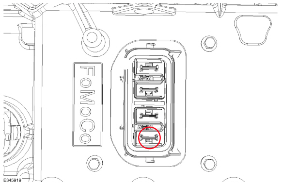
C4236D-1 (component side)
  • For PHEV , measure and record:
    Positive Lead Measurement / Action Negative Lead
    C494-1 (component side) C495-4 (male side)

Is the resistance less than 3 ohms?
Yes GO to AG7
No VERIFY the high voltage high current fuse (150A) is OK
REFER to: High Voltage High Current Fuse - Hybrid Electric Vehicle (HEV) (414-03A High Voltage Battery, Mounting and Cables, Removal and Installation).
or REFER to: High Voltage High Current Fuse - Plug-In Hybrid Electric Vehicle (PHEV) (414-03A High Voltage Battery, Mounting and Cables, Removal and Installation).
If OK, REPAIR circuit. If not OK, REFER to the Wiring Diagrams manual to identify the possible causes of the circuit resistance. INSTALL new high voltage cables from the Inverter System Controller (ISC) to the traction battery, if necessary.REFER to: High Voltage Battery Cables - Hybrid Electric Vehicle (HEV) (414-03A High Voltage Battery, Mounting and Cables, Removal and Installation).

AG7 VERIFY THAT THE CONCERN IS PRESENT

NOTE: Clearing the Inverter System Controller (ISC) Diagnostic Trouble Codes (DTCs) will erase any Inverter System Controller (ISC) recorded freeze frame data. Make sure to record any Inverter System Controller (ISC) freeze frame information before proceeding any further. Refer to the scan tool instruction manual for freeze frame Parameter Identification (PID) menu.

  • INSTALL the Inverter System Controller (ISC) side cover.
    REFER to: Inverter System Controller [SOBDMC] (303-14D Electric Powertrain Control, Removal and Installation).
  • For HEV , inspect the High Voltage Battery Junction Box C4236D and Inverter System Controller (ISC) C199C connectors for damaged or pushed-out pins.
  • For PHEV , inspect Inverter System Controller (ISC) C199C, C494 and C495 connectors for damaged or pushed-out pins.
  • Repair:
    • corrosion, damaged or bent pins, and/or pushed-out pins - replace the high voltage harness between the Inverter System Controller (ISC) and battery
      REFER to: High Voltage Battery Cables - Hybrid Electric Vehicle (HEV) (414-03A High Voltage Battery, Mounting and Cables, Removal and Installation).
  • Connect Inverter System Controller (ISC) C199C .
  • Connect For HEV , High Voltage Battery Junction Box C4236D .
  • Connect For PHEV C494 .
  • Connect For PHEV C495 .
  • Verify the connectors seat and latch correctly.
  • Repower the high voltage system.
    REFER to: High Voltage System De-energizing (414-03A High Voltage Battery, Mounting and Cables, General Procedures).
  • Ignition ON.
  • Clear the Inverter System Controller (ISC) DTC s.
  • Carry out the Inverter System Controller (ISC) self-test.

Is DTC P0DA8 present?
Yes REPLACE the high voltage harness between the Inverter System Controller (ISC) and battery
REFER to: High Voltage Battery Cables - Hybrid Electric Vehicle (HEV) (414-03A High Voltage Battery, Mounting and Cables, Removal and Installation).
No GO to AG8

AG8 CHECK THE HIGH VOLTAGE CABLES FOR AN INTERMITTENT CONCERN
  • Ignition ON.
  • Access the  SOBDMC  and monitor the  GEN_INV_V (V)  PID

  • Carefully wiggle all accessible wiring and connectors associated with the High Voltage Cable from the Inverter System Controller (ISC) to the Traction Battery, and look for a change in the PID state.

Does the voltage vary by more than 10 volts during the wiggle test or by more than 30 volts during the drive cycle test?
Yes REPLACE the high voltage harness between the Inverter System Controller (ISC) and battery
REFER to: High Voltage Battery Cables - Hybrid Electric Vehicle (HEV) (414-03A High Voltage Battery, Mounting and Cables, Removal and Installation).
No The system is operating correctly at this time. The concern may have been caused by a loose or corroded connector.

PINPOINT TEST AH: P0BFD, P1A0E:62, P1A0E:64, P1A0E:96

NOTE: The Inverter System Controller (ISC) is referred to as the SOBDMC (Secondary On-Board Diagnostic Control Module C) in the scan tool.

Normal Operation and Fault Conditions

REFER to: Electric Powertrain Control - System Operation and Component Description (303-14D Electric Powertrain Control, Description and Operation).

DTC Fault Trigger Conditions

DTC Description Fault Trigger Condition
SOBDMC P0BFD:00 Drive Motor 'A' Phase U-V-W Current Sensor Correlation: No Sub Type Information This DTC sets when an internal issue with the Inverter System Controller (ISC) is detected.
SOBDMC P1A0E:62 Hybrid Powertrain Control Module - Motor Disabled: Signal Compare Failure This DTC sets when the motor torque is out of range.
SOBDMC P1A0E:64 Hybrid Powertrain Control Module - Motor Disabled: Signal Plausibility Failure This DTC sets when a plausibility fault with motor torque is detected.
SOBDMC P1A0E:96 Hybrid Powertrain Control Module - Motor Disabled: Component Internal Failure This DTC sets when a motor phase current checksum error is detected.

Possible Sources

  • Other Inverter System Controller (ISC) DTC s
  • Transmission Assembly
  • Inverter System Controller (ISC)
AH1 CHECK FOR INVERTER SYSTEM CONTROLLER (ISC) DIAGNOSTIC TROUBLE CODES (DTCS)
  • Ignition ON.
  • Using a diagnostic scan tool, perform the Inverter System Controller (ISC) self-test.

Are any Inverter System Controller (ISC) DTC s other than P0BFD, P1A0E:62, P1A0E:64 or P1A0E:96 present?
Yes DIAGNOSE all other Inverter System Controller (ISC) DTC s, REFER to the DTC chart in this section.
No GO to AH2

AH2 CHECK THE INVERTER SYSTEM CONTROLLER (ISC) CALIBRATION LEVEL
  • Verify the Inverter System Controller (ISC) is at the latest calibration level.

Is the Inverter System Controller (ISC) at the latest calibration level?
Yes GO to AH3
No UPDATE the Inverter System Controller (ISC) to the latest calibration level.

AH3 VISUAL INSPECTION OF THE HIGH VOLTAGE SYSTEM
  • Ignition OFF.
  • Depower the high voltage system.
    REFER to: High Voltage System De-energizing (414-03A High Voltage Battery, Mounting and Cables, General Procedures).
  • Remove the Inverter System Controller (ISC) side cover. When removing side cover, pull cover straight out approximately 2 inches before moving upwards or damage to the high voltage interlock connector may occur.
    REFER to: Inverter System Controller [SOBDMC] (303-14D Electric Powertrain Control, Removal and Installation).
  • Examine all the high voltage connections for damage and loose or broken conditions.
  • Verify the high voltage terminal bolts are fully seated and torqued to 8  lb.ft ( 10.5  Nm)

Is a concern present?
Yes REPAIR as necessary. CLEAR the Inverter System Controller (ISC) DTC s and REPEAT the self-test.
No GO to AH4

AH4 CHECK FOR MOTOR PHASE CONTINUITY
  • Measure and record:
    Positive Lead Measurement / Action Negative Lead
    ISC/SOBDMC pin 3, component side ISC/SOBDMC pin 4, component side
    ISC/SOBDMC pin 3, component side ISC/SOBDMC pin 5, component side
    ISC/SOBDMC pin 4, component side ISC/SOBDMC pin 5, component side

Is the resistance less than 5 ohms?
Yes GO to AH5
No INSTALL a new Transmission.
REFER to: Transmission (307-01B Automatic Transmission - Automatic Transmission – HF45, Removal and Installation).
CLEAR the Inverter System Controller (ISC) DTC s. REPEAT the self-test.

AH5 CHECK THE ELECTRIC MOTOR FOR A SHORT TO GROUND
  • Measure and record:
    Positive Lead Measurement / Action Negative Lead
    ISC/SOBDMC pin 3, component side   Ground
    ISC/SOBDMC pin 4, component side   Ground
    ISC/SOBDMC pin 5, component side   Ground

Is the resistance greater than 10K ohms?
Yes GO to AH6
No INSTALL a new Transmission.
REFER to: Transmission (307-01B Automatic Transmission - Automatic Transmission – HF45, Removal and Installation).
CLEAR the Inverter System Controller (ISC) DTC s. REPEAT the self-test.

AH6 RECHECK THE INVERTER SYSTEM CONTROLLER (ISC) DIAGNOSTIC TROUBLE CODES (DTCS)
  • Install the Inverter System Controller (ISC) side cover.
    REFER to: Inverter System Controller [SOBDMC] (303-14D Electric Powertrain Control, Removal and Installation).
  • Repower the high voltage system.
    REFER to: High Voltage System De-energizing (414-03A High Voltage Battery, Mounting and Cables, General Procedures).
  • Ignition ON.
  • Using a diagnostic scan tool, clear the Inverter System Controller (ISC) DTC s.
  • Ignition OFF.
  • Ignition ON.
  • Wait 10 seconds.
  • Using a diagnostic scan tool, perform the continuous memory self-test.
  • Check the Inverter System Controller (ISC) DTC s.

Are DTC s P0BFD, P1A0E:62, P1A0E:64 or P1A0E:96 the only DTC s present?
Yes CHECK OASIS for any applicable service articles: TSB , GSB , SSM or FSA . If a service article exists for this concern, DISCONTINUE this test and FOLLOW the service article instructions. If no service articles address this concern, INSTALL a new Inverter System Controller (ISC).
REFER to: Inverter System Controller [SOBDMC] (303-14D Electric Powertrain Control, Removal and Installation).
No The system is operating correctly at this time. The DTC may have set due to high network traffic or an intermittent fault condition. CLEAR the Inverter System Controller (ISC) DTC s and REPEAT the self-test.

PINPOINT TEST AI: P0C17, P0DFC

NOTE: The Inverter System Controller (ISC) is referred to as the SOBDMC (Secondary On-Board Diagnostic Control Module C) in the scan tool.

Normal Operation and Fault Conditions

REFER to: Electric Powertrain Control - System Operation and Component Description (303-14D Electric Powertrain Control, Description and Operation).

DTC Fault Trigger Conditions

DTC Description Fault Trigger Condition
SOBDMC P0C17:00 Drive Motor 'A' Position Sensor Not Learned: No Sub Type Information This DTC sets when the TRID block was either not programmed, erased or lost.
SOBDMC P0DFC:00 Generator Position Sensor Not Learned: No Sub Type Information This DTC sets if the TRID block is programmed, but the data is determined to be out of range.

Possible Sources

  • TRID block programming
  • Inverter System Controller (ISC) calibration
AI1 VERIFY THE INVERTER SYSTEM CONTROLLER (ISC) CALIBRATION LEVEL
  • Verify the Inverter System Controller (ISC) is at the latest calibration level.

Is the Inverter System Controller (ISC) at the latest calibration level?
Yes GO to AI2
No UPDATE the Inverter System Controller (ISC) to the latest calibration level.

AI2 VERIFY THE INVERTER SYSTEM CONTROLLER (ISC) TRID BLOCK HAS BEEN PROGRAMMED CORRECTLY
  • Verify the Inverter System Controller (ISC) TRID block has been programmed correctly. Refer to Module Reprogramming on the scan tool.

Has the TRID block been successfully programmed?
Yes GO to AI3
No CHECK OASIS for any applicable service articles: TSB , GSB , SSM or FSA . If a service article exists for this concern, DISCONTINUE this test and FOLLOW the service article instructions. If no service articles address this concern, reflash the Inverter System Controller (ISC) TRID block.

AI3 REPEAT THE SELF-TEST
  • CLEAR the Inverter System Controller (ISC) DTC s.
  • CARRY out the Inverter System Controller (ISC) self-test.

Is DTC P0C17 or P0DFC present?
Yes CHECK OASIS for any applicable service articles: TSB , GSB , SSM or FSA . If a service article exists for this concern, DISCONTINUE this test and FOLLOW the service article instructions. If no service articles address this concern, reflash the Inverter System Controller (ISC) TRID block. If the concern is still present after the TRID block flash, it is necessary to seek additional help. REFER to the Service Repair And Technical Assistance Process.
No The system is operating correctly at this time. The DTC may have been set due to high network traffic or an intermittent fault condition, the TRID block was not programmed correctly or was erased.

PINPOINT TEST AJ: P0E71

NOTE: The Inverter System Controller (ISC) is referred to as the SOBDMC (Secondary On-Board Diagnostic Control Module C) in the scan tool.

Normal Operation and Fault Conditions

REFER to: Electric Powertrain Control - System Operation and Component Description (303-14D Electric Powertrain Control, Description and Operation).

DTC Fault Trigger Conditions

DTC Description Fault Trigger Condition
SOBDMC P0E71:00 Generator Torque Delivered Performance: No Sub Type Information This DTC sets if the generator system is temporarily disabled and is a notification of other faults in the system.

Possible Sources

  • Other related DTC s within the Inverter System Controller (ISC)
  • Wiring, terminals or connectors
AJ1 CHECK FOR INVERTER SYSTEM CONTROLLER (ISC) DIAGNOSTIC TROUBLE CODES (DTCS)
  • Using a diagnostic scan tool, perform the Inverter System Controller (ISC) self-test.

Is P0E71:00 the only DTC present?
Yes GO to AJ2
No DIAGNOSE all other Inverter System Controller (ISC) DTC s, REFER to the DTC chart in this section.

AJ2 CHECK THE INVERTER SYSTEM CONTROLLER (ISC) CALIBRATION LEVEL
  • Verify the Inverter System Controller (ISC) is at the latest calibration level.

Is the Inverter System Controller (ISC) at the latest calibration level?
Yes The system is operating correctly at this time. The DTC may have been set due to high network traffic or an intermittent fault condition.
No UPDATE the Inverter System Controller (ISC) to the latest calibration level.

PINPOINT TEST AK: P1A07

NOTE: The Inverter System Controller (ISC) is referred to as the SOBDMC (Secondary On-Board Diagnostic Control Module C) in the scan tool.

Normal Operation and Fault Conditions

REFER to: Electric Powertrain Control - System Operation and Component Description (303-14D Electric Powertrain Control, Description and Operation).

DTC Fault Trigger Conditions

DTC Description Fault Trigger Condition
SOBDMC P1A07:00 Inverter High Voltage Performance: No Sub Type Information This DTC sets when the powertrain is trying to protect the battery hardware from extreme voltage (high or low).

Possible Sources

  • Depleted high voltage battery
  • High voltage battery fuse
  • High voltage battery system DTC s
  • High voltage cable connections
  • BECM
AK1 VISUAL INSPECTION OF THE HIGH VOLTAGE SYSTEM
  • Ignition OFF.
  • Depower the high voltage system.
    REFER to: High Voltage System De-energizing (414-03A High Voltage Battery, Mounting and Cables, General Procedures).
  • Remove the Inverter System Controller (ISC) side cover. When removing side cover, pull cover straight out approximately 2 inches before moving upwards or damage to the high voltage interlock connector may occur.
    REFER to: Inverter System Controller [SOBDMC] (303-14D Electric Powertrain Control, Removal and Installation).
  • Examine all the high voltage connections for damage and loose or broken conditions.
  • Verify the high voltage terminal bolts are fully seated and torqued to 8  lb.ft ( 10.5  Nm)

Is a concern present?
Yes REPAIR as necessary. CLEAR the Inverter System Controller (ISC) DTC s and REPEAT the self-test.
No GO to AK2

AK2 VERIFY THE HIGH VOLTAGE TRACTION BATTERY STATE OF CHARGE
  • Install the Inverter System Controller (ISC) side cover.
    REFER to: Inverter System Controller [SOBDMC] (303-14D Electric Powertrain Control, Removal and Installation).
  • Connect all previously disconnected connectors.
  • Re-energize the high voltage system.
    REFER to: High Voltage System De-energizing (414-03A High Voltage Battery, Mounting and Cables, General Procedures).
  • Ignition ON.
  • Access the  SOBDMC  and monitor the  HVBAT_V (V)  PID


Is the voltage greater than 120 volts for HEV or 168 volts for PHEV ?
Yes GO to AK3
No CHARGE the high voltage traction battery.
REFER to: High Voltage Battery Charging - Hybrid Electric Vehicle (HEV) (414-03A High Voltage Battery, Mounting and Cables, General Procedures).
CLEAR the Inverter System Controller (ISC) DTC s. REPEAT the self-test.

AK3 VERIFY CONCERN IS PRESENT

NOTE: Clearing the Inverter System Controller (ISC) Diagnostic Trouble Codes (DTCs) will erase any Inverter System Controller (ISC) recorded freeze frame data. Make sure to record any Inverter System Controller (ISC) freeze frame information before proceeding any further. Refer to the scan tool instruction manual for freeze frame Parameter Identification (PID) menu.

  • CLEAR the Inverter System Controller (ISC) DTC s.
  • CARRY out the Inverter System Controller (ISC) self-test.

Is DTC P1A07 present?
Yes GO to AK4
No GO to AK6

AK4 CHECK THE HIGH VOLTAGE POSITIVE CABLE FOR AN OPEN
  • Ignition OFF.
  • Depower the high voltage system.
    REFER to: High Voltage System De-energizing (414-03A High Voltage Battery, Mounting and Cables, General Procedures).
  • Disconnect High Voltage BJB For HEV C4236D, For PHEV C494 .
  • Disconnect Inverter System Controller (ISC) C199C .
  • Measure and record:

      For HEV


    Positive Lead Measurement / Action Negative Lead
      C4236D-3   C199C-1
      C4236D-4   C199C-4

      For PHEV


    Positive Lead Measurement / Action Negative Lead
      C494-4   C199C-1
      C494-1   C199C-4

Is the resistance less than 5 ohms?
Yes GO to AK5
No INSTALL a new High Voltage Cable from the Inverter System Controller (ISC) to the traction battery.
REFER to: High Voltage Battery Cables - Hybrid Electric Vehicle (HEV) (414-03A High Voltage Battery, Mounting and Cables, Removal and Installation).
. CLEAR the Inverter System Controller (ISC) DTC s. REPEAT the self-test.

AK5 CHECK THE BECM (BATTERY ENERGY CONTROL MODULE) FOR VOLTAGE MISMATCH
  • Ignition ON.
  • CLEAR the Inverter System Controller (ISC) DTC s.
  • Ignition OFF.
  • Wait 5 minutes.
  • Ignition ON.
  • Wait for 5 seconds.
  • Access the  BECM  and monitor the  HVBAT_V (V)  PID

  • Access the  BECM  and monitor the  CONVOLTPOS (V)  PID


Are the PID voltages within 20 volts of each other?
Yes GO to AK6
No INSTALL a new BECM .
REFER to: Battery Energy Control Module (BECM) - Hybrid Electric Vehicle (HEV) (414-03A High Voltage Battery, Mounting and Cables, Removal and Installation).
CLEAR the Inverter System Controller (ISC) DTC s. REPEAT the self-test.

AK6 CHECK THE HIGH VOLTAGE CABLES FOR AN INTERMITTENT CONCERN
  • Ignition OFF.
  • Repair:
    • corrosion (install new connector or terminals – clean module pins)
    • damaged or bent pins – install new terminals/pins
    • pushed-out pins – install new pins as necessary
  • Connect High Voltage BJB For HEV C4236D, For PHEV C494 .
  • Connect Inverter System Controller (ISC) C199C .
  • Repower the high voltage system.
    REFER to: High Voltage System De-energizing (414-03A High Voltage Battery, Mounting and Cables, General Procedures).
  • Ignition ON.
  • Access the  SOBDMC  and monitor the  GEN_INV_V (V)  PID

  • Carefully wiggle all accessible wiring and connectors associated with the High Voltage Cable from the Inverter System Controller (ISC) to the Traction Battery, and look for a change in the PID state.

Is a concern present during the wiggle or drive cycle test?
Yes Repair as necessary.
No The system is operating correctly at this time. The concern may have been caused by a loose or corroded connector.

PINPOINT TEST AL: P1A0A:02

NOTE: The Inverter System Controller (ISC) is referred to as the SOBDMC (Secondary On-Board Diagnostic Control Module C) in the scan tool.

Normal Operation and Fault Conditions

REFER to: Electric Powertrain Control - System Operation and Component Description (303-14D Electric Powertrain Control, Description and Operation).

DTC Fault Trigger Conditions

DTC Description Fault Trigger Condition
SOBDMC P1A0A:02 Immediate Shutdown Signal A: General Signal Failure This DTC sets when the Inverter System Controller (ISC) is commanded to shut down from the BECM or the RCM

Possible Sources

  • High voltage battery DTC s
  • RCM diagnostic trouble codes
AL1 VERIFY THE INVERTER SYSTEM CONTROLLER (ISC) SHUTDOWN REQUEST
  • Confirm the vehicle was not in an accident.

Was the vehicle involved in a collision?
Yes REPAIR any damage to the vehicle. CLEAR the Inverter System Controller (ISC) DTC s.
No GO to AL2

AL2 CHECK THE BECM (BATTERY ENERGY CONTROL MODULE) DIAGNOSTIC TROUBLE CODES (DTCS)
  • Using a diagnostic scan tool, run the BECM self-tests.

Are there any BECM DTC s?
Yes DIAGNOSE and REPAIR any BECM DTC s.
REFER to: High Voltage Battery, Mounting and Cables - Hybrid Electric Vehicle (HEV) (414-03A High Voltage Battery, Mounting and Cables, Diagnosis and Testing).
No GO to AL3

AL3 CHECK THE RCM (RESTRAINTS CONTROL MODULE) DIAGNOSTIC TROUBLE CODES (DTCS)
  • Using a diagnostic scan tool, run the RCM self-tests.

Are there any RCM DTC s?
Yes DIAGNOSE and REPAIR any RCM DTC s.
REFER to: Airbag Supplemental Restraint System (SRS) (501-20B Supplemental Restraint System, Diagnosis and Testing).
No The system is operating correctly at this time. The DTC may have been set due to high network traffic or an intermittent fault condition.

PINPOINT TEST AM: U0100

NOTE: The Inverter System Controller (ISC) is referred to as the SOBDMC (Secondary On-Board Diagnostic Control Module C) in the scan tool.

Normal Operation and Fault Conditions

REFER to: Electric Powertrain Control - System Operation and Component Description (303-14D Electric Powertrain Control, Description and Operation).

DTC Fault Trigger Conditions

DTC Description Fault Trigger Condition
SOBDMC U0100:00 Lost Communication With ECM/PCM 'A': No Sub Type Information This DTC sets when messages are missing from the ECM .

Possible Sources

  • Communications network concern
  • ECM
AM1 VERIFY THE CONCERN
  • Ignition ON.
  • Verify an observable symptom present.

Is an observable symptom present?
Yes GO to AM2
No The system is operating normally at this time. The DTC may have been set due to high network traffic or an intermittent fault condition.

AM2 VERIFY THE DIAGNOSTIC SCAN TOOL COMMUNICATES WITH THE ECM (ENGINE CONTROL MODULE)
  • Connect the diagnostic scan tool to the vehicle.
  • Attempt to establish a vehicle session using the diagnostic scan tool.

Can a vehicle session be established?
Yes GO to AM3
No
REFER to: Communications Network (418-00 Module Communications Network, Diagnosis and Testing).

AM3 CHECK FOR NON-NETWORK DIAGNOSTIC TROUBLE CODES (DTCS)
  • Using a diagnostic scan tool, carry out the Inverter System Controller (ISC) self-test.

Are any non-network DTC s present?
Yes DIAGNOSE all non-network DTC s first. REFER to the appropriate DTC Chart in this section.
No GO to AM4

AM4 CHECK FOR ECM (ENGINE CONTROL MODULE) DIAGNOSTIC TROUBLE CODES (DTCS)
  • Using a diagnostic scan tool, carry out the ECM self-test.

Are any non-network DTC s present?
Yes REFER to Diagnosis and Testing in the appropriate 303-14 section.
No GO to AM5

AM5 CHECK THE INVERTER SYSTEM CONTROLLER (ISC) AND ECM (ENGINE CONTROL MODULE) CALIBRATION LEVELS
  • Verify the Inverter System Controller (ISC) and the ECM are at the latest calibration levels.

Are the Inverter System Controller (ISC) and the ECM at the latest calibration levels?
Yes GO to AM6
No UPDATE the Inverter System Controller (ISC) or ECM to the latest calibration level.

AM6 RECHECK FOR DTC (DIAGNOSTIC TROUBLE CODE) U0100:00
  • Using a diagnostic scan tool, clear the Inverter System Controller (ISC) DTC s.
  • Ignition OFF.
  • Ignition ON.
  • Wait 10 seconds.
  • Using a diagnostic scan tool, carry out the self-test for the Inverter System Controller (ISC).

Is DTC U0100:00 still present?
Yes GO to AM7
No The system is operating correctly at this time. The DTC may have set due to high network traffic or an intermittent fault condition.

AM7 CHECK FOR OTHER CAUSES OF NETWORK COMMUNICATION CONCERN

NOTE: If new modules were installed prior to the DTC being set, the module configuration can be incorrectly set during the PMI or the PMI may not have been carried out.

  • Check the vehicle service history for recent service actions related to the ECM and the Inverter System Controller (ISC). If recent service history is found:
    • verify correct replacement module was installed
      • vehicle parts build list may be used to verify correct part fitment
    • verify the configuration of replacement module was correct
      • re-configure module using as-built data if prior configuration is suspect
    • verify the module was not obtained from a like vehicle and installed into vehicle with concern
      • return the swapped module to source vehicle and obtain new replacement module
  • Operate the system and determine if the observable symptom is still present.

Is the observable symptom still present?
Yes GO to AM8
No The system is operating correctly at this time. The concern may have been due to incorrect parts replacement procedures or incorrect module configuration.

AM8 CHECK FOR CORRECT ECM (ENGINE CONTROL MODULE) OPERATION
  • Ignition OFF.
  • Disconnect and inspect all the ECM connectors.
  • Repair:
    • corrosion (install new connectors or terminals - clean module pins)
    • damaged or bent pins - install new terminals pins
    • pushed-out pins - install new pins as necessary
  • Reconnect the ECM connectors. Make sure they seat and latch correctly.
  • Operate the system and determine if the concern is still present.

Is the concern still present?
Yes CHECK OASIS for any applicable service articles: TSB , GSB , SSM or FSA . If a service article exists for this concern, DISCONTINUE this test and FOLLOW the service article instructions. If no service articles address this concern,
REFER to: Communications Network (418-00 Module Communications Network, Diagnosis and Testing).
No The system is operating correctly at this time. The concern may have been caused by module connections. ADDRESS the root cause of any connector or pin issues.

PINPOINT TEST AN: U0103

NOTE: The Inverter System Controller (ISC) is referred to as the SOBDMC (Secondary On-Board Diagnostic Control Module C) in the scan tool.

Normal Operation and Fault Conditions

REFER to: Electric Powertrain Control - System Operation and Component Description (303-14D Electric Powertrain Control, Description and Operation).

DTC Fault Trigger Conditions

DTC Description Fault Trigger Condition
SOBDMC U0103:87 Lost Communication With Gear Shift Control Module A: Missing Message This DTC sets when messages are missing from the GSM .

Possible Sources

  • Communications network concern
  • GSM
AN1 VERIFY THE CONCERN
  • Ignition ON.
  • Verify an observable symptom present.

Is an observable symptom present?
Yes GO to AN2
No The system is operating normally at this time. The DTC may have been set due to high network traffic or an intermittent fault condition.

AN2 VERIFY THE DIAGNOSTIC SCAN TOOL COMMUNICATES WITH THE GSM (GEAR SHIFT MODULE)
  • Connect the diagnostic scan tool to the vehicle.
  • Attempt to establish a vehicle session using the diagnostic scan tool.

Can a vehicle session be established?
Yes GO to AN3
No
REFER to: Communications Network (418-00 Module Communications Network, Diagnosis and Testing).

AN3 CHECK FOR NON-NETWORK DIAGNOSTIC TROUBLE CODES (DTCS)
  • Using a diagnostic scan tool, carry out the Inverter System Controller (ISC) self-test.

Are any non-network DTC s present?
Yes DIAGNOSE all non-network DTC s first. REFER to the appropriate DTC Chart in this section.
No GO to AN4

AN4 CHECK FOR GSM (GEAR SHIFT MODULE) DIAGNOSTIC TROUBLE CODES (DTCS)
  • Using a diagnostic scan tool, carry out the GSM self-test.

Are any non-network DTC s present?
Yes REFER to Diagnosis and Testing in the appropriate 307-05 section.
No GO to AN5

AN5 CHECK THE INVERTER SYSTEM CONTROLLER (ISC) AND GSM (GEAR SHIFT MODULE) CALIBRATION LEVELS
  • Verify the Inverter System Controller (ISC) and the GSM are at the latest calibration levels.

Are the Inverter System Controller (ISC) and the GSM at the latest calibration levels?
Yes GO to AN6
No UPDATE the Inverter System Controller (ISC) or GSM to the latest calibration level.

AN6 RECHECK FOR DTC (DIAGNOSTIC TROUBLE CODE) U0103:87
  • Using a diagnostic scan tool, clear the Inverter System Controller (ISC) DTC s.
  • Ignition OFF.
  • Ignition ON.
  • Wait 10 seconds.
  • Using a diagnostic scan tool, carry out the self-test for the Inverter System Controller (ISC).

Is DTC U0103:87 still present?
Yes GO to AN7
No The system is operating correctly at this time. The DTC may have set due to high network traffic or an intermittent fault condition.

AN7 CHECK FOR OTHER CAUSES OF NETWORK COMMUNICATION CONCERN

NOTE: If new modules were installed prior to the DTC being set, the module configuration can be incorrectly set during the PMI or the PMI may not have been carried out.

  • Check the vehicle service history for recent service actions related to the GSM and the Inverter System Controller (ISC). If recent service history is found:
    • verify correct replacement module was installed
      • vehicle parts build list may be used to verify correct part fitment
    • verify the configuration of replacement module was correct
      • re-configure module using as-built data if prior configuration is suspect
    • verify the module was not obtained from a like vehicle and installed into vehicle with concern
      • return the swapped module to source vehicle and obtain new replacement module
  • Operate the system and determine if the observable symptom is still present.

Is the observable symptom still present?
Yes GO to AN8
No The system is operating correctly at this time. The concern may have been due to incorrect parts replacement procedures or incorrect module configuration.

AN8 CHECK FOR CORRECT GSM (GEAR SHIFT MODULE) OPERATION
  • Ignition OFF.
  • Disconnect and inspect all the GSM connectors.
  • Repair:
    • corrosion (install new connectors or terminals - clean module pins)
    • damaged or bent pins - install new terminals pins
    • pushed-out pins - install new pins as necessary
  • Reconnect the GSM connectors. Make sure they seat and latch correctly.
  • Operate the system and determine if the concern is still present.

Is the concern still present?
Yes CHECK OASIS for any applicable service articles: TSB , GSB , SSM or FSA . If a service article exists for this concern, DISCONTINUE this test and FOLLOW the service article instructions. If no service articles address this concern,
REFER to: Communications Network (418-00 Module Communications Network, Diagnosis and Testing).
No The system is operating correctly at this time. The concern may have been caused by module connections. ADDRESS the root cause of any connector or pin issues.

PINPOINT TEST AO: U010F

NOTE: The Inverter System Controller (ISC) is referred to as the SOBDMC (Secondary On-Board Diagnostic Control Module C) in the scan tool.

Normal Operation and Fault Conditions

REFER to: Electric Powertrain Control - System Operation and Component Description (303-14D Electric Powertrain Control, Description and Operation).

DTC Fault Trigger Conditions

DTC Description Fault Trigger Condition
SOBDMC U010F:00 Lost Communication With Air Conditioning Control Module: No Sub Type Information This DTC sets when messages are missing from the ACCM .

Possible Sources

  • Communications network concern
  • ACCM
AO1 VERIFY THE CONCERN
  • Ignition ON.
  • Verify an observable symptom present.

Is an observable symptom present?
Yes GO to AO2
No The system is operating normally at this time. The DTC may have been set due to high network traffic or an intermittent fault condition.

AO2 VERIFY THE DIAGNOSTIC SCAN TOOL COMMUNICATES WITH THE ACCM (AIR CONDITIONING CONTROL MODULE)
  • Connect the diagnostic scan tool to the vehicle.
  • Attempt to establish a vehicle session using the diagnostic scan tool.

Can a vehicle session be established?
Yes GO to AO3
No
REFER to: Communications Network (418-00 Module Communications Network, Diagnosis and Testing).

AO3 CHECK FOR NON-NETWORK DIAGNOSTIC TROUBLE CODES (DTCS)
  • Using a diagnostic scan tool, carry out the Inverter System Controller (ISC) self-test.

Are any non-network DTC s present?
Yes DIAGNOSE all non-network DTC s first. REFER to the appropriate DTC Chart in this section.
No GO to AO4

AO4 CHECK FOR ACCM (AIR CONDITIONING CONTROL MODULE) DIAGNOSTIC TROUBLE CODES (DTCS)
  • Using a diagnostic scan tool, carry out the ACCM self-test.

Are any non-network DTC s present?
Yes REFER to Diagnosis and Testing in the appropriate 412-00 section.
No GO to AO5

AO5 CHECK THE INVERTER SYSTEM CONTROLLER (ISC) AND ACCM (AIR CONDITIONING CONTROL MODULE) CALIBRATION LEVELS
  • Verify the Inverter System Controller (ISC) and the ACCM are at the latest calibration levels.

Are the Inverter System Controller (ISC) and the ACCM at the latest calibration levels?
Yes GO to AO6
No UPDATE the Inverter System Controller (ISC) or ACCM to the latest calibration level.

AO6 RECHECK FOR DTC (DIAGNOSTIC TROUBLE CODE) U010F:00
  • Using a diagnostic scan tool, clear the Inverter System Controller (ISC) DTC s.
  • Ignition OFF.
  • Ignition ON.
  • Wait 10 seconds.
  • Using a diagnostic scan tool, carry out the self-test for the Inverter System Controller (ISC).

Is DTC U010F:00 still present?
Yes GO to AO7
No The system is operating correctly at this time. The DTC may have set due to high network traffic or an intermittent fault condition.

AO7 CHECK FOR OTHER CAUSES OF NETWORK COMMUNICATION CONCERN

NOTE: If new modules were installed prior to the DTC being set, the module configuration can be incorrectly set during the PMI or the PMI may not have been carried out.

  • Check the vehicle service history for recent service actions related to the ACCM and the Inverter System Controller (ISC). If recent service history is found:
    • verify correct replacement module was installed
      • vehicle parts build list may be used to verify correct part fitment
    • verify the configuration of replacement module was correct
      • re-configure module using as-built data if prior configuration is suspect
    • verify the module was not obtained from a like vehicle and installed into vehicle with concern
      • return the swapped module to source vehicle and obtain new replacement module
  • Operate the system and determine if the observable symptom is still present.

Is the observable symptom still present?
Yes GO to AO8
No The system is operating correctly at this time. The concern may have been due to incorrect parts replacement procedures or incorrect module configuration.

AO8 CHECK FOR CORRECT ACCM (AIR CONDITIONING CONTROL MODULE) OPERATION
  • Ignition OFF.
  • Disconnect and inspect all the ACCM connectors.
  • Repair:
    • corrosion (install new connectors or terminals - clean module pins)
    • damaged or bent pins - install new terminals pins
    • pushed-out pins - install new pins as necessary
  • Reconnect the ACCM connectors. Make sure they seat and latch correctly.
  • Operate the system and determine if the concern is still present.

Is the concern still present?
Yes CHECK OASIS for any applicable service articles: TSB , GSB , SSM or FSA . If a service article exists for this concern, DISCONTINUE this test and FOLLOW the service article instructions. If no service articles address this concern,
REFER to: Communications Network (418-00 Module Communications Network, Diagnosis and Testing).
No The system is operating correctly at this time. The concern may have been caused by module connections. ADDRESS the root cause of any connector or pin issues.

PINPOINT TEST AP: U0111

NOTE: The Inverter System Controller (ISC) is referred to as the SOBDMC (Secondary On-Board Diagnostic Control Module C) in the scan tool.

Normal Operation and Fault Conditions

REFER to: Electric Powertrain Control - System Operation and Component Description (303-14D Electric Powertrain Control, Description and Operation).

DTC Fault Trigger Conditions

DTC Description Fault Trigger Condition
SOBDMC U0111:00 Lost Communication With Battery Energy Control Module 'A': No Sub Type Information This DTC sets when messages are missing from the BECM .

Possible Sources

  • Communication concern
  • BECM
AP1 VERIFY THE CONCERN
  • Ignition ON.
  • Verify an observable symptom present.

Is an observable symptom present?
Yes GO to AP2
No The system is operating normally at this time. The DTC may have been set due to high network traffic or an intermittent fault condition.

AP2 VERIFY THE DIAGNOSTIC SCAN TOOL COMMUNICATES WITH THE BECM (BATTERY ENERGY CONTROL MODULE)
  • Connect the diagnostic scan tool to the vehicle.
  • Attempt to establish a vehicle session using the diagnostic scan tool.

Can a vehicle session be established?
Yes GO to AP3
No
REFER to: Communications Network (418-00 Module Communications Network, Diagnosis and Testing).

AP3 CHECK FOR NON-NETWORK DIAGNOSTIC TROUBLE CODES (DTCS)
  • Using a diagnostic scan tool, carry out the Inverter System Controller (ISC) self-test.

Are any non-network DTC s present?
Yes DIAGNOSE all non-network DTC s first. REFER to the appropriate DTC Chart in this section.
No GO to AP4

AP4 CHECK FOR BECM (BATTERY ENERGY CONTROL MODULE) DIAGNOSTIC TROUBLE CODES (DTCS)
  • Using a diagnostic scan tool, carry out the BECM self-test.

Are any non-network DTC s present?
Yes REFER to Diagnosis and Testing in the appropriate 414-03 section.
No GO to AP5

AP5 CHECK THE INVERTER SYSTEM CONTROLLER (ISC) AND BECM (BATTERY ENERGY CONTROL MODULE) CALIBRATION LEVELS
  • Verify the Inverter System Controller (ISC) and the BECM are at the latest calibration levels.

Are the Inverter System Controller (ISC) and the BECM at the latest calibration levels?
Yes GO to AP6
No UPDATE the Inverter System Controller (ISC) or BECM to the latest calibration level.

AP6 RECHECK FOR DTC (DIAGNOSTIC TROUBLE CODE) U0111
  • Using a diagnostic scan tool, clear the Inverter System Controller (ISC) DTC s.
  • Ignition OFF.
  • Ignition ON.
  • Wait 10 seconds.
  • Using a diagnostic scan tool, carry out the self-test for the Inverter System Controller (ISC).

Is DTC U0111 still present?
Yes GO to AP7
No The system is operating correctly at this time. The DTC may have set due to high network traffic or an intermittent fault condition.

AP7 CHECK FOR OTHER CAUSES OF NETWORK COMMUNICATION CONCERN

NOTE: If new modules were installed prior to the DTC being set, the module configuration can be incorrectly set during the PMI or the PMI may not have been carried out.

  • Check the vehicle service history for recent service actions related to the BECM and the Inverter System Controller (ISC). If recent service history is found:
    • verify correct replacement module was installed
      • vehicle parts build list may be used to verify correct part fitment
    • verify the configuration of replacement module was correct
      • re-configure module using as-built data if prior configuration is suspect
    • verify the module was not obtained from a like vehicle and installed into vehicle with concern
      • return the swapped module to source vehicle and obtain new replacement module
  • Operate the system and determine if the observable symptom is still present.

Is the observable symptom still present?
Yes GO to AP8
No The system is operating correctly at this time. The concern may have been due to incorrect parts replacement procedures or incorrect module configuration.

AP8 CHECK FOR CORRECT BECM (BATTERY ENERGY CONTROL MODULE) OPERATION
  • Ignition OFF.
  • Disconnect and inspect all the BECM connectors.
  • Repair:
    • corrosion (install new connectors or terminals - clean module pins)
    • damaged or bent pins - install new terminals pins
    • pushed-out pins - install new pins as necessary
  • Reconnect the BECM connectors. Make sure they seat and latch correctly.
  • Operate the system and determine if the concern is still present.

Is the concern still present?
Yes CHECK OASIS for any applicable service articles: TSB , GSB , SSM or FSA . If a service article exists for this concern, DISCONTINUE this test and FOLLOW the service article instructions. If no service articles address this concern,
REFER to: Communications Network (418-00 Module Communications Network, Diagnosis and Testing).
No The system is operating correctly at this time. The concern may have been caused by module connections. ADDRESS the root cause of any connector or pin issues.

PINPOINT TEST AQ: U0121

NOTE: The Inverter System Controller (ISC) is referred to as the SOBDMC (Secondary On-Board Diagnostic Control Module C) in the scan tool.

Normal Operation and Fault Conditions

REFER to: Electric Powertrain Control - System Operation and Component Description (303-14D Electric Powertrain Control, Description and Operation).

DTC Fault Trigger Conditions

DTC Description Fault Trigger Condition
SOBDMC U0121:00 Lost Communication With Anti-Lock Brake System (ABS) Control Module 'A': No Sub Type Information This DTC sets when messages are missing from the ABS module.
SOBDMC U0121:8F Lost Communication With Anti-Lock Brake System (ABS) Control Module 'A': Erratic This DTC sets when messages are missing from the ABS module.

Possible Sources

  • Communications network concern
  • ABS module
AQ1 VERIFY THE CONCERN
  • Ignition ON.
  • Verify there is an observable symptom present.

Is an observable symptom present?
Yes GO to AQ2
No CLEAR the DTC . The system is operating correctly at this time. The DTC may have been set due to high network traffic or an intermittent fault condition.

AQ2 VERIFY THE DIAGNOSTIC SCAN TOOL COMMUNICATES WITH THE ABS (ANTI-LOCK BRAKE SYSTEM) MODULE
  • Connect the diagnostic scan tool to the vehicle.
  • Attempt to establish a vehicle session using the diagnostic scan tool.

Can a vehicle session be established?
Yes GO to AQ3
No
REFER to: Communications Network (418-00 Module Communications Network, Diagnosis and Testing).

AQ3 CHECK FOR NON-NETWORK DIAGNOSTIC TROUBLE CODES (DTCS)
  • Using a diagnostic scan tool, carry out the Inverter System Controller (ISC) self-test.

Are any non-network DTC s present?
Yes DIAGNOSE all non-network DTC s first. REFER to the DTC Chart in this section.
No GO to AQ4

AQ4 CHECK FOR NON-NETWORK ABS (ANTI-LOCK BRAKE SYSTEM) MODULE DIAGNOSTIC TROUBLE CODES (DTCS)
  • Using a diagnostic scan tool, carry out the ABS module self-test.

Are any non-network DTC s present?
Yes REFER to Diagnosis and Testing in the appropriate 206-09 section.
No GO to AQ5

AQ5 CHECK THE INVERTER SYSTEM CONTROLLER (ISC) AND ABS (ANTI-LOCK BRAKE SYSTEM) MODULE CALIBRATION LEVELS
  • Verify the Inverter System Controller (ISC) and the ABS module are at the latest calibration levels.

Are the Inverter System Controller (ISC) and the ABS module at the latest calibration levels?
Yes GO to AQ6
No UPDATE the Inverter System Controller (ISC) or ABS module to the latest calibration level.

AQ6 RECHECK FOR DTC (DIAGNOSTIC TROUBLE CODE) U0121:00 AND U0121:8F
  • Using a diagnostic scan tool, clear the Inverter System Controller (ISC) DTC s.
  • Ignition OFF.
  • Ignition ON.
  • Wait 10 seconds.
  • Using a diagnostic scan tool, carry out the self-test for the Inverter System Controller (ISC).

Is DTC U0121:00 or U0121:8F still present?
Yes GO to AQ7
No The system is operating correctly at this time. The DTC may have been set due to high network traffic or an intermittent fault condition.

AQ7 CHECK FOR OTHER CAUSES OF NETWORK COMMUNICATION CONCERN

NOTE: If new modules were installed prior to the DTC being set, the module configuration can be incorrectly set during the PMI or the PMI may not have been carried out.

  • Check the vehicle service history for recent service actions related to the ABS module and the Inverter System Controller (ISC). If recent service history is found:
    • verify correct replacement module was installed
      • vehicle parts build list may be used to verify correct part fitment
    • verify the configuration of replacement module was correct
      • re-configure module using as-built data if prior configuration is suspect
    • verify the module was not obtained from a like vehicle and installed into vehicle with concern
      • return the swapped module to source vehicle and obtain new replacement module
  • Operate the system and determine if the observable symptom is still present.

Is the observable symptom still present?
Yes GO to AQ8
No The system is operating correctly at this time. The concern may have been due to incorrect parts replacement procedures or incorrect module configuration.

AQ8 CHECK FOR CORRECT ABS (ANTI-LOCK BRAKE SYSTEM) MODULE OPERATION
  • Ignition OFF.
  • Disconnect and inspect the ABS module connectors.
  • Repair:
    • corrosion (install new connectors or terminals - clean module pins)
    • damaged or bent pins - install new terminals pins
    • pushed-out pins - install new pins as necessary
  • Reconnect the ABS module connectors. Make sure they seat and latch correctly.
  • Operate the system and determine if the concern is still present.

Is the concern still present?
Yes CHECK OASIS for any applicable service articles: TSB , GSB , SSM or FSA . If a service article exists for this concern, DISCONTINUE this test and FOLLOW the service article instructions. If no service articles address this concern,
REFER to: Communications Network (418-00 Module Communications Network, Diagnosis and Testing).
No The system is operating correctly at this time. The concern may have been caused by module connections. ADDRESS the root cause of any connector or pin issues.

PINPOINT TEST AR: U0140

NOTE: The Inverter System Controller (ISC) is referred to as the SOBDMC (Secondary On-Board Diagnostic Control Module C) in the scan tool.

Normal Operation and Fault Conditions

REFER to: Electric Powertrain Control - System Operation and Component Description (303-14D Electric Powertrain Control, Description and Operation).

DTC Fault Trigger Conditions

DTC Description Fault Trigger Condition
SOBDMC U0140:00 Lost Communication With Body Control Module: No Sub Type Information This DTC sets when messages are missing from the BCM .

Possible Sources

  • Communications network concern
  • BCM
AR1 VERIFY THE CONCERN
  • Ignition ON.
  • Verify there is an observable symptom present.

Is an observable symptom present?
Yes GO to AR2
No CLEAR the DTC . The system is operating correctly at this time. The DTC may have been set due to high network traffic or an intermittent fault condition.

AR2 VERIFY THE DIAGNOSTIC SCAN TOOL COMMUNICATES WITH THE BCM (BODY CONTROL MODULE)
  • Connect the diagnostic scan tool to the vehicle.
  • Attempt to establish a vehicle session using the diagnostic scan tool.

Can a vehicle session be established?
Yes GO to AR3
No
REFER to: Communications Network (418-00 Module Communications Network, Diagnosis and Testing).

AR3 CHECK FOR NON-NETWORK DIAGNOSTIC TROUBLE CODES (DTCS)
  • Using a diagnostic scan tool, carry out the Inverter System Controller (ISC) self-test.

Are any non-network DTC s present?
Yes DIAGNOSE all non-network DTC s first. REFER to the DTC Chart in this section.
No GO to AR4

AR4 CHECK FOR NON-NETWORK BCM (BODY CONTROL MODULE) DIAGNOSTIC TROUBLE CODES (DTCS)
  • Using a diagnostic scan tool, carry out the BCM self-test.

Are any non-network DTC s present?
Yes REFER to Diagnosis and Testing in the appropriate 419-10 section.
No GO to AR5

AR5 CHECK THE INVERTER SYSTEM CONTROLLER (ISC) AND BCM (BODY CONTROL MODULE) CALIBRATION LEVELS
  • Verify the Inverter System Controller (ISC) and the BCM are at the latest calibration levels.

Are the Inverter System Controller (ISC) and the BCM at the latest calibration levels?
Yes GO to AR6
No UPDATE the Inverter System Controller (ISC) or BCM to the latest calibration level.

AR6 RECHECK FOR DTC (DIAGNOSTIC TROUBLE CODE) U0140
  • Using a diagnostic scan tool, clear the Inverter System Controller (ISC) DTC s.
  • Ignition OFF.
  • Ignition ON.
  • Wait 10 seconds.
  • Using a diagnostic scan tool, carry out the self-test for the Inverter System Controller (ISC).

Is DTC U0140 present?
Yes GO to AR7
No The system is operating correctly at this time. The DTC may have been set due to high network traffic or an intermittent fault condition.

AR7 CHECK FOR OTHER CAUSES OF NETWORK COMMUNICATION CONCERN

NOTE: If new modules were installed prior to the DTC being set, the module configuration can be incorrectly set during the PMI or the PMI may not have been carried out.

  • Check the vehicle service history for recent service actions related to the BCM and the Inverter System Controller (ISC). If recent service history is found:
    • verify correct replacement module was installed
      • vehicle parts build list may be used to verify correct part fitment
    • verify the configuration of replacement module was correct
      • re-configure module using as-built data if prior configuration is suspect
    • verify the module was not obtained from a like vehicle and installed into vehicle with concern
      • return the swapped module to source vehicle and obtain new replacement module
  • Operate the system and determine if the observable symptom is still present.

Is the observable symptom still present?
Yes GO to AR8
No The system is operating correctly at this time. The concern may have been due to incorrect parts replacement procedures or incorrect module configuration.

AR8 CHECK FOR CORRECT BCM (BODY CONTROL MODULE) OPERATION
  • Ignition OFF.
  • Disconnect and inspect the BCM connectors.
  • Repair:
    • corrosion (install new connectors or terminals - clean module pins)
    • damaged or bent pins - install new terminals pins
    • pushed-out pins - install new pins as necessary
  • Reconnect the BCM connectors. Make sure they seat and latch correctly.
  • Operate the system and determine if the concern is still present.

Is the concern still present?
Yes CHECK OASIS for any applicable service articles: TSB , GSB , SSM or FSA . If a service article exists for this concern, DISCONTINUE this test and FOLLOW the service article instructions. If no service articles address this concern,
REFER to: Communications Network (418-00 Module Communications Network, Diagnosis and Testing).
No The system is operating correctly at this time. The concern may have been caused by module connections. ADDRESS the root cause of any connector or pin issues.

PINPOINT TEST AS: U0143

NOTE: The Inverter System Controller (ISC) is referred to as the SOBDMC (Secondary On-Board Diagnostic Control Module C) in the scan tool.

Normal Operation and Fault Conditions

REFER to: Electric Powertrain Control - System Operation and Component Description (303-14D Electric Powertrain Control, Description and Operation).

DTC Fault Trigger Conditions

DTC Description Fault Trigger Condition
SOBDMC U0143:00 Lost Communication With Body Control Module 'C': No Sub Type Information This DTC sets when messages are missing from the BCMC .

Possible Sources

  • Communications network concern
  • BCMC
AS1 VERIFY THE CONCERN
  • Ignition ON.
  • Verify there is an observable symptom present.

Is an observable symptom present?
Yes GO to AS2
No CLEAR the DTC . The system is operating correctly at this time. The DTC may have been set due to high network traffic or an intermittent fault condition.

AS2 VERIFY THE DIAGNOSTIC SCAN TOOL COMMUNICATES WITH THE BCMC (BODY CONTROL MODULE C)
  • Connect the diagnostic scan tool to the vehicle.
  • Attempt to establish a vehicle session using the diagnostic scan tool.

Can a vehicle session be established?
Yes GO to AS3
No
REFER to: Communications Network (418-00 Module Communications Network, Diagnosis and Testing).

AS3 CHECK FOR NON-NETWORK DIAGNOSTIC TROUBLE CODES (DTCS)
  • Using a diagnostic scan tool, carry out the Inverter System Controller (ISC) self-test.

Are any non-network DTC s present?
Yes DIAGNOSE all non-network DTC s first. REFER to the DTC Chart in this section.
No GO to AS4

AS4 CHECK FOR NON-NETWORK BCMC (BODY CONTROL MODULE C) DIAGNOSTIC TROUBLE CODES (DTCS)
  • Using a diagnostic scan tool, carry out the BCMC self-test.

Are any non-network DTC s present?
Yes
REFER to: Body Control Module C (BCMC) (419-10 Multifunction Electronic Modules, Diagnosis and Testing).
No GO to AS5

AS5 CHECK THE INVERTER SYSTEM CONTROLLER (ISC) AND BCMC (BODY CONTROL MODULE C) CALIBRATION LEVELS
  • Verify the Inverter System Controller (ISC) and the BCMC are at the latest calibration levels.

Are the Inverter System Controller (ISC) and the BCMC at the latest calibration levels?
Yes GO to AS6
No UPDATE the Inverter System Controller (ISC) or BCMC to the latest calibration level.

AS6 RECHECK FOR DTC (DIAGNOSTIC TROUBLE CODE) U0143
  • Using a diagnostic scan tool, clear the Inverter System Controller (ISC) DTC s.
  • Ignition OFF.
  • Ignition ON.
  • Wait 10 seconds.
  • Using a diagnostic scan tool, carry out the self-test for the Inverter System Controller (ISC).

Is DTC U0143 present?
Yes GO to AS7
No The system is operating correctly at this time. The DTC may have been set due to high network traffic or an intermittent fault condition.

AS7 CHECK FOR OTHER CAUSES OF NETWORK COMMUNICATION CONCERN

NOTE: If new modules were installed prior to the DTC being set, the module configuration can be incorrectly set during the PMI or the PMI may not have been carried out.

  • Check the vehicle service history for recent service actions related to the BCMC and the Inverter System Controller (ISC). If recent service history is found:
    • verify correct replacement module was installed
      • vehicle parts build list may be used to verify correct part fitment
    • verify the configuration of replacement module was correct
      • re-configure module using as-built data if prior configuration is suspect
    • verify the module was not obtained from a like vehicle and installed into vehicle with concern
      • return the swapped module to source vehicle and obtain new replacement module
  • Operate the system and determine if the observable symptom is still present.

Is the observable symptom still present?
Yes GO to AS8
No The system is operating correctly at this time. The concern may have been due to incorrect parts replacement procedures or incorrect module configuration.

AS8 CHECK FOR CORRECT BCMC (BODY CONTROL MODULE C) OPERATION
  • Ignition OFF.
  • Disconnect and inspect the BCMC connectors.
  • Repair:
    • corrosion (install new connectors or terminals - clean module pins)
    • damaged or bent pins - install new terminals pins
    • pushed-out pins - install new pins as necessary
  • Reconnect the BCMC connectors. Make sure they seat and latch correctly.
  • Operate the system and determine if the concern is still present.

Is the concern still present?
Yes CHECK OASIS for any applicable service articles: TSB , GSB , SSM or FSA . If a service article exists for this concern, DISCONTINUE this test and FOLLOW the service article instructions. If no service articles address this concern,
REFER to: Communications Network (418-00 Module Communications Network, Diagnosis and Testing).
No The system is operating correctly at this time. The concern may have been caused by module connections. ADDRESS the root cause of any connector or pin issues.

PINPOINT TEST AT: U0151

NOTE: The Inverter System Controller (ISC) is referred to as the SOBDMC (Secondary On-Board Diagnostic Control Module C) in the scan tool.

Normal Operation and Fault Conditions

REFER to: Electric Powertrain Control - System Operation and Component Description (303-14D Electric Powertrain Control, Description and Operation).

DTC Fault Trigger Conditions

DTC Description Fault Trigger Condition
SOBDMC U0151:00 Lost Communication With Restraints Control Module: No Sub Type Information This DTC sets when messages are missing from the RCM .

Possible Sources

  • Communications network concern
  • RCM
AT1 VERIFY THE CONCERN
  • Ignition ON.
  • Verify there is an observable symptom present.

Is an observable symptom present?
Yes GO to AT2
No CLEAR the DTC . The system is operating correctly at this time. The DTC may have been set due to high network traffic or an intermittent fault condition.

AT2 VERIFY THE DIAGNOSTIC SCAN TOOL COMMUNICATES WITH THE RCM (RESTRAINTS CONTROL MODULE)
  • Connect the diagnostic scan tool to the vehicle.
  • Attempt to establish a vehicle session using the diagnostic scan tool.

Can a vehicle session be established?
Yes GO to AT3
No
REFER to: Communications Network (418-00 Module Communications Network, Diagnosis and Testing).

AT3 CHECK FOR NON-NETWORK DIAGNOSTIC TROUBLE CODES (DTCS)
  • Using a diagnostic scan tool, carry out the Inverter System Controller (ISC) self-test.

Are any non-network DTC s present?
Yes DIAGNOSE all non-network DTC s first. REFER to the DTC Chart in this section.
No GO to AT4

AT4 CHECK FOR NON-NETWORK RCM (RESTRAINTS CONTROL MODULE) DIAGNOSTIC TROUBLE CODES (DTCS)
  • Using a diagnostic scan tool, carry out the RCM self-test.

Are any non-network DTC s present?
Yes REFER to Diagnosis and Testing in the appropriate 501-20B section.
No GO to AT5

AT5 CHECK THE INVERTER SYSTEM CONTROLLER (ISC) AND RCM (RESTRAINTS CONTROL MODULE) CALIBRATION LEVELS
  • Verify the Inverter System Controller (ISC) and the RCM are at the latest calibration levels.

Are the Inverter System Controller (ISC) and the RCM at the latest calibration levels?
Yes GO to AT6
No UPDATE the Inverter System Controller (ISC) or RCM to the latest calibration level.

AT6 RECHECK FOR DTC (DIAGNOSTIC TROUBLE CODE) U0151
  • Using a diagnostic scan tool, clear the Inverter System Controller (ISC) DTC s.
  • Ignition OFF.
  • Ignition ON.
  • Wait 10 seconds.
  • Using a diagnostic scan tool, carry out the self-test for the Inverter System Controller (ISC).

Is DTC U0151 present?
Yes GO to AT7
No The system is operating correctly at this time. The DTC may have been set due to high network traffic or an intermittent fault condition.

AT7 CHECK FOR OTHER CAUSES OF NETWORK COMMUNICATION CONCERN

NOTE: If new modules were installed prior to the DTC being set, the module configuration can be incorrectly set during the PMI or the PMI may not have been carried out.

  • Check the vehicle service history for recent service actions related to the RCM and the Inverter System Controller (ISC). If recent service history is found:
    • verify correct replacement module was installed
      • vehicle parts build list may be used to verify correct part fitment
    • verify the configuration of replacement module was correct
      • re-configure module using as-built data if prior configuration is suspect
    • verify the module was not obtained from a like vehicle and installed into vehicle with concern
      • return the swapped module to source vehicle and obtain new replacement module
  • Operate the system and determine if the observable symptom is still present.

Is the observable symptom still present?
Yes GO to AT8
No The system is operating correctly at this time. The concern may have been due to incorrect parts replacement procedures or incorrect module configuration.

AT8 CHECK FOR CORRECT RCM (RESTRAINTS CONTROL MODULE) OPERATION
  • Ignition OFF.
  • Disconnect and inspect the RCM connectors.
  • Repair:
    • corrosion (install new connectors or terminals - clean module pins)
    • damaged or bent pins - install new terminals pins
    • pushed-out pins - install new pins as necessary
  • Reconnect the RCM connectors. Make sure they seat and latch correctly.
  • Operate the system and determine if the concern is still present.

Is the concern still present?
Yes CHECK OASIS for any applicable service articles: TSB , GSB , SSM or FSA . If a service article exists for this concern, DISCONTINUE this test and FOLLOW the service article instructions. If no service articles address this concern,
REFER to: Communications Network (418-00 Module Communications Network, Diagnosis and Testing).
No The system is operating correctly at this time. The concern may have been caused by module connections. ADDRESS the root cause of any connector or pin issues.

PINPOINT TEST AU: U0155

NOTE: The Inverter System Controller (ISC) is referred to as the SOBDMC (Secondary On-Board Diagnostic Control Module C) in the scan tool.

Normal Operation and Fault Conditions

REFER to: Electric Powertrain Control - System Operation and Component Description (303-14D Electric Powertrain Control, Description and Operation).

DTC Fault Trigger Conditions

DTC Description Fault Trigger Condition
SOBDMC U0155:00 Lost Communication With Instrument Panel Cluster (IPC) Control Module: No Sub Type Information This DTC sets when messages are missing from the IPC .

Possible Sources

  • Communications network concern
  • IPC
AU1 VERIFY THE CONCERN
  • Ignition ON.
  • Verify there is an observable symptom present.

Is an observable symptom present?
Yes GO to AU2
No CLEAR the DTC . The system is operating correctly at this time. The DTC may have been set due to high network traffic or an intermittent fault condition.

AU2 VERIFY THE DIAGNOSTIC SCAN TOOL COMMUNICATES WITH THE IPC (INSTRUMENT PANEL CLUSTER)
  • Connect the diagnostic scan tool to the vehicle.
  • Attempt to establish a vehicle session using the diagnostic scan tool.

Can a vehicle session be established?
Yes GO to AU3
No
REFER to: Communications Network (418-00 Module Communications Network, Diagnosis and Testing).

AU3 CHECK FOR NON-NETWORK DIAGNOSTIC TROUBLE CODES (DTCS)
  • Using a diagnostic scan tool, carry out the Inverter System Controller (ISC) self-test.

Are any non-network DTC s present?
Yes DIAGNOSE all non-network DTC s first. REFER to the DTC Chart in this section.
No GO to AU4

AU4 CHECK FOR NON-NETWORK IPC (INSTRUMENT PANEL CLUSTER) DIAGNOSTIC TROUBLE CODES (DTCS)
  • Using a diagnostic scan tool, carry out the IPC self-test.

Are any non-network DTC s present?
Yes REFER to Diagnosis and Testing in the appropriate 413-00 section.
No GO to AU5

AU5 CHECK THE INVERTER SYSTEM CONTROLLER (ISC) AND IPC (INSTRUMENT PANEL CLUSTER) CALIBRATION LEVELS
  • Verify the Inverter System Controller (ISC) and the IPC are at the latest calibration levels.

Are the Inverter System Controller (ISC) and the IPC at the latest calibration levels?
Yes GO to AU6
No UPDATE the Inverter System Controller (ISC) or IPC to the latest calibration level.

AU6 RECHECK FOR DTC (DIAGNOSTIC TROUBLE CODE) U0155
  • Using a diagnostic scan tool, clear the Inverter System Controller (ISC) DTC s.
  • Ignition OFF.
  • Ignition ON.
  • Wait 10 seconds.
  • Using a diagnostic scan tool, carry out the self-test for the Inverter System Controller (ISC).

Is DTC U0155 present?
Yes GO to AU7
No The system is operating correctly at this time. The DTC may have been set due to high network traffic or an intermittent fault condition.

AU7 CHECK FOR OTHER CAUSES OF NETWORK COMMUNICATION CONCERN

NOTE: If new modules were installed prior to the DTC being set, the module configuration can be incorrectly set during the PMI or the PMI may not have been carried out.

  • Check the vehicle service history for recent service actions related to the IPC and the Inverter System Controller (ISC). If recent service history is found:
    • verify correct replacement module was installed
      • vehicle parts build list may be used to verify correct part fitment
    • verify the configuration of replacement module was correct
      • re-configure module using as-built data if prior configuration is suspect
    • verify the module was not obtained from a like vehicle and installed into vehicle with concern
      • return the swapped module to source vehicle and obtain new replacement module
  • Operate the system and determine if the observable symptom is still present.

Is the observable symptom still present?
Yes GO to AU8
No The system is operating correctly at this time. The concern may have been due to incorrect parts replacement procedures or incorrect module configuration.

AU8 CHECK FOR CORRECT IPC (INSTRUMENT PANEL CLUSTER) OPERATION
  • Ignition OFF.
  • Disconnect and inspect the IPC connectors.
  • Repair:
    • corrosion (install new connectors or terminals - clean module pins)
    • damaged or bent pins - install new terminals pins
    • pushed-out pins - install new pins as necessary
  • Reconnect the IPC connectors. Make sure they seat and latch correctly.
  • Operate the system and determine if the concern is still present.

Is the concern still present?
Yes CHECK OASIS for any applicable service articles: TSB , GSB , SSM or FSA . If a service article exists for this concern, DISCONTINUE this test and FOLLOW the service article instructions. If no service articles address this concern,
REFER to: Communications Network (418-00 Module Communications Network, Diagnosis and Testing).
No The system is operating correctly at this time. The concern may have been caused by module connections. ADDRESS the root cause of any connector or pin issues.

PINPOINT TEST AV: U0159

NOTE: The Inverter System Controller (ISC) is referred to as the SOBDMC (Secondary On-Board Diagnostic Control Module C) in the scan tool.

Normal Operation and Fault Conditions

REFER to: Electric Powertrain Control - System Operation and Component Description (303-14D Electric Powertrain Control, Description and Operation).

DTC Fault Trigger Conditions

DTC Description Fault Trigger Condition
SOBDMC U0159:87 Lost Communication With Parking Assist Control Module 'A': Missing Message This DTC sets if data messages received from the PAM (part of the BCM ) are missing.

Possible Sources

  • Communication concern
  • PAM
AV1 VERIFY THE CONCERN
  • Ignition ON.
  • Verify there is an observable symptom present.

Is an observable symptom present?
Yes GO to AV2
No CLEAR the DTC . The system is operating correctly at this time. The DTC may have been set due to high network traffic or an intermittent fault condition.

AV2 VERIFY THE DIAGNOSTIC SCAN TOOL COMMUNICATES WITH THE PAM (PARKING ASSIST CONTROL MODULE)
  • Connect the diagnostic scan tool to the vehicle.
  • Attempt to establish a vehicle session using the diagnostic scan tool.

Can a vehicle session be established?
Yes GO to AV3
No
REFER to: Communications Network (418-00 Module Communications Network, Diagnosis and Testing).

AV3 CHECK FOR NON-NETWORK DIAGNOSTIC TROUBLE CODES (DTCS)
  • Using a diagnostic scan tool, perform the Inverter System Controller (ISC) self-test.

Are any non-network DTC s present?
Yes DIAGNOSE all non-network DTC s first. REFER to the appropriate DTC chart in this section.
No GO to AV4

AV4 CHECK FOR NON-NETWORK PAM (PARKING ASSIST CONTROL MODULE) DIAGNOSTIC TROUBLE CODES (DTCS)
  • Using a diagnostic scan tool, perform the PAM self-test.

Are any non-network DTC s present?
Yes REFER to Diagnosis and Testing in the appropriate 413-13 section.
No GO to AV5

AV5 CHECK THE INVERTER SYSTEM CONTROLLER (ISC) AND PAM (PARKING ASSIST CONTROL MODULE) CALIBRATION LEVELS
  • Verify the Inverter System Controller (ISC) and the PAM are at the latest calibration levels.

Are the Inverter System Controller (ISC) and the PAM at the latest calibration levels?
Yes GO to AV6
No UPDATE the Inverter System Controller (ISC) or PAM to the latest calibration level.

AV6 RECHECK FOR DTC (DIAGNOSTIC TROUBLE CODE) U0159
  • Using the scan tool, clear the Inverter System Controller (ISC) DTC s.
  • Ignition OFF.
  • Ignition ON.
  • Wait 10 seconds.
  • Using a diagnostic scan tool, carry out the Inverter System Controller (ISC) self-test.

Is DTC U0159 present?
Yes GO to AV7
No The system is operating correctly at this time. The DTC may have been set due to high network traffic or an intermittent fault condition.

AV7 CHECK FOR OTHER CAUSES OF NETWORK COMMUNICATION CONCERN
  • If new modules were installed prior to the DTC being set, the module configuration can be incorrectly set during the PMI or the PMI may not have been carried out.
  • Check the vehicle service history for recent service actions related to the PAM and the Inverter System Controller (ISC). If recent service history is found:
    • Verify correct replacement module was installed, vehicle parts build list may be used to verify correct part fitment.
    • Verify the configuration of replacement module was correct, re-configure module using as-built data if prior configuration is suspect.
    • Verify the module was not obtained from a like vehicle and installed into vehicle with concern, return the swapped module to source vehicle and obtain new replacement module.
  • Operate the system and determine if the observable symptom is still present.

Is the observable symptom still present?
Yes GO to AV8
No The system is operating correctly at this time. The DTC may have been set due to high network traffic or an intermittent fault condition.

AV8 CHECK FOR CORRECT PAM (PARKING ASSIST CONTROL MODULE) OPERATION
  • Ignition OFF.
  • Disconnect and inspect all the PAM connectors.
  • Repair:
    • Corrosion (install new connector or terminals – clean module pins)
    • Damaged or bent pins – install new terminals/pins
    • Pushed-out pins – install new pins as necessary
  • Reconnect the PAM connectors. Make sure they seat and latch correctly.
  • Ignition ON.
  • Operate the system and determine if the concern is still present.

Is the concern still present?
Yes CHECK OASIS for any applicable service articles: TSB , GSB , SSM or FSA . If a service article exists for this concern, DISCONTINUE this test and FOLLOW the service article instructions. If no service articles address this concern,
REFER to: Communications Network (418-00 Module Communications Network, Diagnosis and Testing).
No The system is operating correctly at this time. The concern may have been caused by module connections. ADDRESS the root cause of any connector or pin issues.

PINPOINT TEST AW: U0164

NOTE: The Inverter System Controller (ISC) is referred to as the SOBDMC (Secondary On-Board Diagnostic Control Module C) in the scan tool.

Normal Operation and Fault Conditions

REFER to: Electric Powertrain Control - System Operation and Component Description (303-14D Electric Powertrain Control, Description and Operation).

DTC Fault Trigger Conditions

DTC Description Fault Trigger Condition
SOBDMC U0164:00 Lost Communication With HVAC Control Module: No Sub Type Information This DTC sets when messages are missing from the HVAC module.

Possible Sources

  • Communications network concern
  • HVAC module.
AW1 VERIFY THE CONCERN
  • Ignition ON.
  • Verify there is an observable symptom present.

Is an observable symptom present?
Yes GO to AW2
No CLEAR the DTC . The system is operating correctly at this time. The DTC may have been set due to high network traffic or an intermittent fault condition.

AW2 VERIFY THE DIAGNOSTIC SCAN TOOL COMMUNICATES WITH THE HVAC (HEATING, VENTILATION AND AIR CONDITIONING) MODULE
  • Connect the diagnostic scan tool to the vehicle.
  • Attempt to establish a vehicle session using the diagnostic scan tool.

Can a vehicle session be established?
Yes GO to AW3
No
REFER to: Communications Network (418-00 Module Communications Network, Diagnosis and Testing).

AW3 CHECK FOR NON-NETWORK DIAGNOSTIC TROUBLE CODES (DTCS)
  • Using a diagnostic scan tool, carry out the Inverter System Controller (ISC) self-test.

Are any non-network DTC s present?
Yes DIAGNOSE all non-network DTC s first. REFER to the DTC Chart in this section.
No GO to AW4

AW4 CHECK FOR NON-NETWORK HVAC (HEATING, VENTILATION AND AIR CONDITIONING) MODULE DIAGNOSTIC TROUBLE CODES (DTCS)
  • Using a diagnostic scan tool, carry out the HVAC module self-test.

Are any non-network DTC s present?
Yes
REFER to: Climate Control System - Vehicles With: Dual Automatic Temperature Control (DATC)/Electronic Automatic Temperature Control (EATC) (412-00 Climate Control System - General Information, Diagnosis and Testing).
No GO to AW5

AW5 CHECK THE INVERTER SYSTEM CONTROLLER (ISC) AND HVAC (HEATING, VENTILATION AND AIR CONDITIONING) MODULE CALIBRATION LEVELS
  • Verify the Inverter System Controller (ISC) and the HVAC module are at the latest calibration levels.

Are the Inverter System Controller (ISC) and the HVAC module at the latest calibration levels?
Yes GO to AW6
No UPDATE the Inverter System Controller (ISC) or HVAC module to the latest calibration level.

AW6 RECHECK FOR DTC (DIAGNOSTIC TROUBLE CODE) U0164
  • Using a diagnostic scan tool, clear the Inverter System Controller (ISC) DTC s.
  • Ignition OFF.
  • Ignition ON.
  • Wait 10 seconds.
  • Using a diagnostic scan tool, carry out the self-test for the Inverter System Controller (ISC).

Is DTC U0164 present?
Yes GO to AW7
No The system is operating correctly at this time. The DTC may have been set due to high network traffic or an intermittent fault condition.

AW7 CHECK FOR OTHER CAUSES OF NETWORK COMMUNICATION CONCERN

NOTE: If new modules were installed prior to the DTC being set, the module configuration can be incorrectly set during the PMI or the PMI may not have been carried out.

  • Check the vehicle service history for recent service actions related to the HVAC module and the Inverter System Controller (ISC). If recent service history is found:
    • verify correct replacement module was installed
      • vehicle parts build list may be used to verify correct part fitment
    • verify the configuration of replacement module was correct
      • re-configure module using as-built data if prior configuration is suspect
    • verify the module was not obtained from a like vehicle and installed into vehicle with concern
      • return the swapped module to source vehicle and obtain new replacement module
  • Operate the system and determine if the observable symptom is still present.

Is the observable symptom still present?
Yes GO to AW8
No The system is operating correctly at this time. The concern may have been due to incorrect parts replacement procedures or incorrect module configuration.

AW8 CHECK FOR CORRECT HVAC (HEATING, VENTILATION AND AIR CONDITIONING) MODULE OPERATION
  • Ignition OFF.
  • Disconnect and inspect the HVAC module connectors.
  • Repair:
    • corrosion (install new connectors or terminals - clean module pins)
    • damaged or bent pins - install new terminals pins
    • pushed-out pins - install new pins as necessary
  • Reconnect the HVAC module connectors. Make sure they seat and latch correctly.
  • Operate the system and determine if the concern is still present.

Is the concern still present?
Yes CHECK OASIS for any applicable service articles: TSB , GSB , SSM or FSA . If a service article exists for this concern, DISCONTINUE this test and FOLLOW the service article instructions. If no service articles address this concern,
REFER to: Communications Network (418-00 Module Communications Network, Diagnosis and Testing).
No The system is operating correctly at this time. The concern may have been caused by module connections. ADDRESS the root cause of any connector or pin issues.

PINPOINT TEST AX: U016A:00

NOTE: The Inverter System Controller (ISC) is referred to as the SOBDMC (Secondary On-Board Diagnostic Control Module C) in the scan tool.

Normal Operation and Fault Conditions

REFER to: Electric Powertrain Control - System Operation and Component Description (303-14D Electric Powertrain Control, Description and Operation).

DTC Fault Trigger Conditions

DTC Description Fault Trigger Condition
SOBDMC U016A:00 Lost Communication With Global Positioning System Module: No Sub Type Information This DTC sets when messages are missing from the GPSM .

Possible Sources

  • Communications network concern
  • GPSM
AX1 VERIFY THE CONCERN
  • Ignition ON.
  • Verify there is an observable symptom present.

Is an observable symptom present?
Yes GO to AX2
No The system is operating correctly at this time. The DTC may have been set due to high network traffic or an intermittent fault condition. Using the scan tool, clear the Inverter System Controller (ISC) DTC s.

AX2 VERIFY THE DIAGNOSTIC SCAN TOOL COMMUNICATES WITH THE GPSM (GLOBAL POSITIONING SYSTEM MODULE)
  • Connect the diagnostic scan tool to the vehicle.
  • Attempt to establish a vehicle session using the diagnostic scan tool.

Can a vehicle session be established?
Yes GO to AX3
No
REFER to: Communications Network (418-00 Module Communications Network, Diagnosis and Testing).

AX3 CHECK FOR NON-NETWORK DIAGNOSTIC TROUBLE CODES (DTCS)
  • Using a diagnostic scan tool, perform the Inverter System Controller (ISC) self-test.

Are any non-network DTC s present?
Yes DIAGNOSE all non-network DTC s first. REFER to the appropriate DTC chart in this section.
No GO to AX4

AX4 CHECK FOR NON-NETWORK GPSM (GLOBAL POSITIONING SYSTEM MODULE) DIAGNOSTIC TROUBLE CODES (DTCS)
  • Using a diagnostic scan tool, perform the GPSM self-test.

Are any non-network DTC s present?
Yes REFER to Diagnosis and Testing in the appropriate 415-00 section.
No GO to AX5

AX5 CHECK THE INVERTER SYSTEM CONTROLLER (ISC) AND GPSM (GLOBAL POSITIONING SYSTEM MODULE) CALIBRATION LEVELS
  • Verify the Inverter System Controller (ISC) and the GPSM are at the latest calibration levels.

Are the Inverter System Controller (ISC) and the GPSM at the latest calibration levels?
Yes GO to AX6
No UPDATE the Inverter System Controller (ISC) or GPSM to the latest calibration level.

AX6 RECHECK FOR DTC (DIAGNOSTIC TROUBLE CODE) U016A
  • Using the scan tool, clear the Inverter System Controller (ISC) DTC s.
  • Ignition OFF.
  • Ignition ON.
  • Wait 10 seconds.
  • Using a diagnostic scan tool, carry out the Inverter System Controller (ISC) self-test.

Is DTC U016A still present?
Yes GO to AX7
No The system is operating correctly at this time. The DTC may have been set due to high network traffic or an intermittent fault condition.

AX7 CHECK FOR OTHER CAUSES OF NETWORK COMMUNICATION CONCERN
  • If new modules were installed prior to the DTC being set, the module configuration can be incorrectly set during the PMI or the PMI may not have been carried out.
  • Check the vehicle service history for recent service actions related to the GPSM and the Inverter System Controller (ISC). If recent service history is found:
    • Verify correct replacement module was installed, vehicle parts build list may be used to verify correct part fitment.
    • Verify the configuration of replacement module was correct, re-configure module using as-built data if prior configuration is suspect.
    • Verify the module was not obtained from a like vehicle and installed into vehicle with concern, return the swapped module to source vehicle and obtain new replacement module.
  • Operate the system and determine if the observable symptom is still present.

Is the observable symptom still present?
Yes GO to AX8
No The system is operating correctly at this time. The DTC may have been set due to high network traffic or an intermittent fault condition.

AX8 CHECK FOR CORRECT GPSM (GLOBAL POSITIONING SYSTEM MODULE) OPERATION
  • Ignition OFF.
  • Disconnect and inspect all GPSM connectors.
  • Repair:
    • Corrosion (install new connector or terminals – clean module pins)
    • Damaged or bent pins – install new terminals/pins
    • Pushed-out pins – install new pins as necessary
  • Reconnect the GPSM connectors. Make sure they seat and latch correctly.
  • Ignition ON.
  • Operate the system and determine if the concern is still present.

Is the concern still present?
Yes CHECK OASIS for any applicable service articles: TSB , GSB , SSM or FSA . If a service article exists for this concern, DISCONTINUE this test and FOLLOW the service article instructions. If no service articles address this concern,
REFER to: Communications Network (418-00 Module Communications Network, Diagnosis and Testing).
No The system is operating correctly at this time. The concern may have been caused by module connections. ADDRESS the root cause of any connector or pin issues.

PINPOINT TEST AY: U0198

NOTE: The Inverter System Controller (ISC) is referred to as the SOBDMC (Secondary On-Board Diagnostic Control Module C) in the scan tool.

Normal Operation and Fault Conditions

REFER to: Electric Powertrain Control - System Operation and Component Description (303-14D Electric Powertrain Control, Description and Operation).

DTC Fault Trigger Conditions

DTC Description Fault Trigger Condition
SOBDMC U0198:00 Lost Communication With Telematic Control Module 'A': No Sub Type Information This DTC sets when messages are missing from the TCU .

Possible Sources

  • Communications network concern
  • TCU
AY1 VERIFY THE CONCERN
  • Ignition ON.
  • Verify there is an observable symptom present.

Is an observable symptom present?
Yes GO to AY2
No The system is operating correctly at this time. The DTC may have been set due to high network traffic or an intermittent fault condition. Using the scan tool, clear the Inverter System Controller (ISC) DTC s.

AY2 VERIFY THE DIAGNOSTIC SCAN TOOL COMMUNICATES WITH THE TCU (TELEMATIC CONTROL UNIT MODULE)
  • Connect the diagnostic scan tool to the vehicle.
  • Attempt to establish a vehicle session using the diagnostic scan tool.

Can a vehicle session be established?
Yes GO to AY3
No
REFER to: Communications Network (418-00 Module Communications Network, Diagnosis and Testing).

AY3 CHECK FOR NON-NETWORK DIAGNOSTIC TROUBLE CODES (DTCS)
  • Using a diagnostic scan tool, perform the Inverter System Controller (ISC) self-test.

Are any non-network DTC s present?
Yes DIAGNOSE all non-network DTC s first. REFER to the appropriate DTC chart in this section.
No GO to AY4

AY4 CHECK FOR NON-NETWORK TCU (TELEMATIC CONTROL UNIT MODULE) DIAGNOSTIC TROUBLE CODES (DTCS)
  • Using a diagnostic scan tool, perform the TCU self-test.

Are any non-network DTC s present?
Yes REFER to Diagnosis and Testing in the appropriate 415-00 section.
No GO to AY5

AY5 CHECK THE INVERTER SYSTEM CONTROLLER (ISC) AND TCU (TELEMATIC CONTROL UNIT MODULE) CALIBRATION LEVELS
  • Verify the Inverter System Controller (ISC) and the TCU are at the latest calibration levels.

Are the Inverter System Controller (ISC) and the TCU at the latest calibration levels?
Yes GO to AY6
No UPDATE the Inverter System Controller (ISC) or TCU to the latest calibration level.

AY6 RECHECK FOR DTC (DIAGNOSTIC TROUBLE CODE) U0198
  • Using the scan tool, clear the Inverter System Controller (ISC) DTC s.
  • Ignition OFF.
  • Ignition ON.
  • Wait 10 seconds.
  • Using a diagnostic scan tool, carry out the Inverter System Controller (ISC) self-test.

Is DTC U0198 still present?
Yes GO to AY7
No The system is operating correctly at this time. The DTC may have been set due to high network traffic or an intermittent fault condition.

AY7 CHECK FOR OTHER CAUSES OF NETWORK COMMUNICATION CONCERN
  • If new modules were installed prior to the DTC being set, the module configuration can be incorrectly set during the PMI or the PMI may not have been carried out.
  • Check the vehicle service history for recent service actions related to the TCU and the Inverter System Controller (ISC). If recent service history is found:
    • Verify correct replacement module was installed, vehicle parts build list may be used to verify correct part fitment.
    • Verify the configuration of replacement module was correct, re-configure module using as-built data if prior configuration is suspect.
    • Verify the module was not obtained from a like vehicle and installed into vehicle with concern, return the swapped module to source vehicle and obtain new replacement module.
  • Operate the system and determine if the observable symptom is still present.

Is the observable symptom still present?
Yes GO to AY8
No The system is operating correctly at this time. The DTC may have been set due to high network traffic or an intermittent fault condition.

AY8 CHECK FOR CORRECT TCU (TELEMATIC CONTROL UNIT MODULE) OPERATION
  • Ignition OFF.
  • Disconnect and inspect all TCU connectors.
  • Repair:
    • Corrosion (install new connector or terminals – clean module pins)
    • Damaged or bent pins – install new terminals/pins
    • Pushed-out pins – install new pins as necessary
  • Reconnect the TCU connectors. Make sure they seat and latch correctly.
  • Ignition ON.
  • Operate the system and determine if the concern is still present.

Is the concern still present?
Yes CHECK OASIS for any applicable service articles: TSB , GSB , SSM or FSA . If a service article exists for this concern, DISCONTINUE this test and FOLLOW the service article instructions. If no service articles address this concern,
REFER to: Communications Network (418-00 Module Communications Network, Diagnosis and Testing).
No The system is operating correctly at this time. The concern may have been caused by module connections. ADDRESS the root cause of any connector or pin issues.

PINPOINT TEST AZ: U019B

NOTE: The Inverter System Controller (ISC) is referred to as the SOBDMC (Secondary On-Board Diagnostic Control Module C) in the scan tool.

Normal Operation and Fault Conditions

REFER to: Electric Powertrain Control - System Operation and Component Description (303-14D Electric Powertrain Control, Description and Operation).

DTC Fault Trigger Conditions

DTC Description Fault Trigger Condition
SOBDMC U019B:00 Lost Communication With Battery Charger Control Module 'A': No Sub Type Information This DTC sets when messages are missing from the SOBDM .

Possible Sources

  • Communications network concern
  • SOBDM (Battery Charger Control Module)
AZ1 VERIFY THE CONCERN
  • Ignition ON.
  • Verify there is an observable symptom present.

Is an observable symptom present?
Yes GO to AZ2
No The system is operating correctly at this time. The DTC may have been set due to high network traffic or an intermittent fault condition. Using the scan tool, clear the Inverter System Controller (ISC) DTC s.

AZ2 VERIFY THE DIAGNOSTIC SCAN TOOL COMMUNICATES WITH THE SOBDM (SECONDARY ON-BOARD DIAGNOSTIC CONTROL MODULE A)
  • Connect the diagnostic scan tool to the vehicle.
  • Attempt to establish a vehicle session using the diagnostic scan tool.

Can a vehicle session be established?
Yes GO to AZ3
No
REFER to: Communications Network (418-00 Module Communications Network, Diagnosis and Testing).

AZ3 CHECK FOR NON-NETWORK DIAGNOSTIC TROUBLE CODES (DTCS)
  • Using a diagnostic scan tool, perform the Inverter System Controller (ISC) self-test.

Are any non-network DTC s present?
Yes DIAGNOSE all non-network DTC s first. REFER to the appropriate DTC chart in this section.
No GO to AZ4

AZ4 CHECK FOR NON-NETWORK SOBDM (SECONDARY ON-BOARD DIAGNOSTIC CONTROL MODULE A) DIAGNOSTIC TROUBLE CODES (DTCS)
  • Using a diagnostic scan tool, perform the SOBDM self-test.

Are any non-network DTC s present?
Yes REFER to Diagnosis and Testing in the appropriate 414-03 section.
No GO to AZ5

AZ5 CHECK THE INVERTER SYSTEM CONTROLLER (ISC) AND SOBDM (SECONDARY ON-BOARD DIAGNOSTIC CONTROL MODULE A) CALIBRATION LEVELS
  • Verify the Inverter System Controller (ISC) also known as the SOBDMC can and the Battery Charger Control Module (also known as the SOBDM ) are at the latest calibration levels.

Are the Inverter System Controller (ISC) and the SOBDM at the latest calibration levels?
Yes GO to AZ6
No UPDATE the Inverter System Controller (ISC) or SOBDM to the latest calibration level.

AZ6 RECHECK FOR DTC (DIAGNOSTIC TROUBLE CODE) U019B
  • Using the scan tool, clear the Inverter System Controller (ISC) DTC s.
  • Ignition OFF.
  • Ignition ON.
  • Wait 10 seconds.
  • Using a diagnostic scan tool, carry out the Inverter System Controller (ISC) self-test.

Is DTC U019B still present?
Yes GO to AZ7
No The system is operating correctly at this time. The DTC may have been set due to high network traffic or an intermittent fault condition.

AZ7 CHECK FOR OTHER CAUSES OF NETWORK COMMUNICATION CONCERN
  • If new modules were installed prior to the DTC being set, the module configuration can be incorrectly set during the PMI or the PMI may not have been carried out.
  • Check the vehicle service history for recent service actions related to the SOBDM and the Inverter System Controller (ISC). If recent service history is found:
    • Verify correct replacement module was installed, vehicle parts build list may be used to verify correct part fitment.
    • Verify the configuration of replacement module was correct, re-configure module using as-built data if prior configuration is suspect.
    • Verify the module was not obtained from a like vehicle and installed into vehicle with concern, return the swapped module to source vehicle and obtain new replacement module.
  • Operate the system and determine if the observable symptom is still present.

Is the observable symptom still present?
Yes GO to AZ8
No The system is operating correctly at this time. The DTC may have been set due to high network traffic or an intermittent fault condition.

AZ8 CHECK FOR CORRECT SOBDM (SECONDARY ON-BOARD DIAGNOSTIC CONTROL MODULE A) OPERATION
  • Ignition OFF.
  • Disconnect and inspect all the SOBDM connectors.
  • Repair:
    • Corrosion (install new connector or terminals – clean module pins)
    • Damaged or bent pins – install new terminals/pins
    • Pushed-out pins – install new pins as necessary
  • Reconnect the SOBDM connectors. Make sure they seat and latch correctly.
  • Ignition ON.
  • Operate the system and determine if the concern is still present.

Is the concern still present?
Yes CHECK OASIS for any applicable service articles: TSB , GSB , SSM or FSA . If a service article exists for this concern, DISCONTINUE this test and FOLLOW the service article instructions. If no service articles address this concern,
REFER to: Communications Network (418-00 Module Communications Network, Diagnosis and Testing).
No The system is operating correctly at this time. The concern may have been caused by module connections. ADDRESS the root cause of any connector or pin issues.

PINPOINT TEST BA: U0214

NOTE: The Inverter System Controller (ISC) is referred to as the SOBDMC (Secondary On-Board Diagnostic Control Module C) in the scan tool.

Normal Operation and Fault Conditions

REFER to: Electric Powertrain Control - System Operation and Component Description (303-14D Electric Powertrain Control, Description and Operation).

DTC Fault Trigger Conditions

DTC Description Fault Trigger Condition
SOBDMC U0214:00 Lost Communication With Remote Function Actuation Module: No Sub Type Information This DTC sets when messages are missing from the RFA module.

Possible Sources

  • Communications network concern
  • RFA module
BA1 VERIFY THE CONCERN
  • Ignition ON.
  • Verify there is an observable symptom present.

Is an observable symptom present?
Yes GO to BA2
No The system is operating correctly at this time. The DTC may have been set due to high network traffic or an intermittent fault condition. Using the scan tool, clear the Inverter System Controller (ISC) DTC s.

BA2 VERIFY THE DIAGNOSTIC SCAN TOOL COMMUNICATES WITH THE RFA (REMOTE FUNCTION ACTUATOR) MODULE
  • Connect the diagnostic scan tool to the vehicle.
  • Attempt to establish a vehicle session using the diagnostic scan tool.

Can a vehicle session be established?
Yes GO to BA3
No
REFER to: Communications Network (418-00 Module Communications Network, Diagnosis and Testing).

BA3 CHECK FOR NON-NETWORK DIAGNOSTIC TROUBLE CODES (DTCS)
  • Using a diagnostic scan tool, perform the Inverter System Controller (ISC) self-test.

Are any non-network DTC s present?
Yes DIAGNOSE all non-network DTC s first. REFER to the appropriate DTC chart in this section.
No GO to BA4

BA4 CHECK FOR NON-NETWORK RFA (REMOTE FUNCTION ACTUATOR) MODULE DIAGNOSTIC TROUBLE CODES (DTCS)
  • Using a diagnostic scan tool, perform the RFA module self-test.

Are any non-network DTC s present?
Yes REFER to Diagnosis and Testing in the appropriate 419-10 section.
No GO to BA5

BA5 CHECK THE INVERTER SYSTEM CONTROLLER (ISC) AND RFA (REMOTE FUNCTION ACTUATOR) MODULE CALIBRATION LEVELS
  • Verify the Inverter System Controller (ISC) and the RFA module are at the latest calibration levels.

Are the Inverter System Controller (ISC) and the RFA module at the latest calibration levels?
Yes GO to BA6
No UPDATE the Inverter System Controller (ISC) or RFA module to the latest calibration level.

BA6 RECHECK FOR DTC (DIAGNOSTIC TROUBLE CODE) U0214
  • Using the scan tool, clear the Inverter System Controller (ISC) DTC s.
  • Ignition OFF.
  • Ignition ON.
  • Wait 10 seconds.
  • Using a diagnostic scan tool, carry out the Inverter System Controller (ISC) self-test.

Is DTC U0214 present?
Yes GO to BA7
No The system is operating correctly at this time. The DTC may have been set due to high network traffic or an intermittent fault condition.

BA7 CHECK FOR OTHER CAUSES OF NETWORK COMMUNICATION CONCERN
  • If new modules were installed prior to the DTC being set, the module configuration can be incorrectly set during the PMI or the PMI may not have been carried out.
  • Check the vehicle service history for recent service actions related to the RFA module and the Inverter System Controller (ISC). If recent service history is found:
    • Verify correct replacement module was installed, vehicle parts build list may be used to verify correct part fitment.
    • Verify the configuration of replacement module was correct, re-configure module using as-built data if prior configuration is suspect.
    • Verify the module was not obtained from a like vehicle and installed into vehicle with concern, return the swapped module to source vehicle and obtain new replacement module.
  • Operate the system and determine if the observable symptom is still present.

Is the observable symptom still present?
Yes GO to BA8
No The system is operating correctly at this time. The DTC may have been set due to high network traffic or an intermittent fault condition.

BA8 CHECK FOR CORRECT RFA (REMOTE FUNCTION ACTUATOR) MODULE OPERATION
  • Ignition OFF.
  • Disconnect and inspect all the RFA module connectors.
  • Repair:
    • Corrosion (install new connector or terminals – clean module pins)
    • Damaged or bent pins – install new terminals/pins
    • Pushed-out pins – install new pins as necessary
  • Reconnect the RFA module connectors. Make sure they seat and latch correctly.
  • Ignition ON.
  • Operate the system and determine if the concern is still present.

Is the concern still present?
Yes CHECK OASIS for any applicable service articles: TSB , GSB , SSM or FSA . If a service article exists for this concern, DISCONTINUE this test and FOLLOW the service article instructions. If no service articles address this concern,
REFER to: Communications Network (418-00 Module Communications Network, Diagnosis and Testing).
No The system is operating correctly at this time. The concern may have been caused by module connections. ADDRESS the root cause of any connector or pin issues.

PINPOINT TEST BB: U023A

NOTE: The Inverter System Controller (ISC) is referred to as the SOBDMC (Secondary On-Board Diagnostic Control Module C) in the scan tool.

Normal Operation and Fault Conditions

REFER to: Electric Powertrain Control - System Operation and Component Description (303-14D Electric Powertrain Control, Description and Operation).

DTC Fault Trigger Conditions

DTC Description Fault Trigger Condition
SOBDMC U023A:00 Lost Communication With Image Processing Module A: No Sub Type Information This DTC sets if data messages from the IPMA are missing.

Possible Sources

  • Communications network concern
  • IPMA
BB1 VERIFY THE CONCERN
  • Ignition ON.
  • Verify there is an observable symptom present.

Is an observable symptom present?
Yes GO to BB2
No The system is operating correctly at this time. The DTC may have been set due to high network traffic or an intermittent fault condition. Using the scan tool, clear the Inverter System Controller (ISC) DTC s.

BB2 VERIFY THE DIAGNOSTIC SCAN TOOL COMMUNICATES WITH THE IPMA (IMAGE PROCESSING MODULE A)
  • Connect the diagnostic scan tool to the vehicle.
  • Attempt to establish a vehicle session using the diagnostic scan tool.

Can a vehicle session be established?
Yes GO to BB3
No
REFER to: Communications Network (418-00 Module Communications Network, Diagnosis and Testing).

BB3 CHECK FOR NON-NETWORK DIAGNOSTIC TROUBLE CODES (DTCS)
  • Using a diagnostic scan tool, perform the Inverter System Controller (ISC) self-test.

Are any non-network DTC s present?
Yes DIAGNOSE all non-network DTC s first. REFER to the appropriate DTC chart in this section.
No GO to BB4

BB4 CHECK FOR NON-NETWORK IPMA (IMAGE PROCESSING MODULE A) DIAGNOSTIC TROUBLE CODES (DTCS)
  • Using a diagnostic scan tool, perform the IPMA self-test.

Are any non-network DTC s present?
Yes REFER to Diagnosis and Testing in the appropriate 419-07 section.
No GO to BB5

BB5 CHECK THE INVERTER SYSTEM CONTROLLER (ISC) AND IPMA (IMAGE PROCESSING MODULE A) CALIBRATION LEVELS
  • Verify the Inverter System Controller (ISC) and the IPMA are at the latest calibration levels.

Are the Inverter System Controller (ISC) and the IPMA at the latest calibration levels?
Yes GO to BB6
No UPDATE the Inverter System Controller (ISC) or IPMA to the latest calibration level.

BB6 RECHECK FOR DTC (DIAGNOSTIC TROUBLE CODE) U023A
  • Using the scan tool, clear the Inverter System Controller (ISC) DTC s.
  • Ignition OFF.
  • Ignition ON.
  • Wait 10 seconds.
  • Using a diagnostic scan tool, carry out the Inverter System Controller (ISC) self-test.

Is DTC U023A present?
Yes GO to BB7
No The system is operating correctly at this time. The DTC may have been set due to high network traffic or an intermittent fault condition.

BB7 CHECK FOR OTHER CAUSES OF NETWORK COMMUNICATION CONCERN
  • If new modules were installed prior to the DTC being set, the module configuration can be incorrectly set during the PMI or the PMI may not have been carried out.
  • Check the vehicle service history for recent service actions related to the IPMA and the Inverter System Controller (ISC). If recent service history is found:
    • Verify correct replacement module was installed, vehicle parts build list may be used to verify correct part fitment.
    • Verify the configuration of replacement module was correct, re-configure module using as-built data if prior configuration is suspect.
    • Verify the module was not obtained from a like vehicle and installed into vehicle with concern, return the swapped module to source vehicle and obtain new replacement module.
  • Operate the system and determine if the observable symptom is still present.

Is the observable symptom still present?
Yes GO to BB8
No The system is operating correctly at this time. The DTC may have been set due to high network traffic or an intermittent fault condition.

BB8 CHECK FOR CORRECT IPMA (IMAGE PROCESSING MODULE A) OPERATION
  • Ignition OFF.
  • Disconnect and inspect all the IPMA connectors.
  • Repair:
    • Corrosion (install new connector or terminals – clean module pins)
    • Damaged or bent pins – install new terminals/pins
    • Pushed-out pins – install new pins as necessary
  • Reconnect the IPMA connectors. Make sure they seat and latch correctly.
  • Ignition ON.
  • Operate the system and determine if the concern is still present.

Is the concern still present?
Yes CHECK OASIS for any applicable service articles: TSB , GSB , SSM or FSA . If a service article exists for this concern, DISCONTINUE this test and FOLLOW the service article instructions. If no service articles address this concern,
REFER to: Communications Network (418-00 Module Communications Network, Diagnosis and Testing).
No The system is operating correctly at this time. The concern may have been caused by module connections. ADDRESS the root cause of any connector or pin issues.

PINPOINT TEST BC: U0253:87

NOTE: The Inverter System Controller (ISC) is referred to as the SOBDMC (Secondary On-Board Diagnostic Control Module C) in the scan tool.

Normal Operation and Fault Conditions

REFER to: Electric Powertrain Control - System Operation and Component Description (303-14D Electric Powertrain Control, Description and Operation).

DTC Fault Trigger Conditions

DTC Description Fault Trigger Condition
SOBDMC U0253:87 Lost Communication With Accessory Protocol Interface Module: Missing Message This DTC sets when messages are missing from the APIM .

Possible Sources

  • Communications network concern
  • APIM
BC1 VERIFY THE CONCERN
  • Ignition ON.
  • Verify there is an observable symptom present.

Is an observable symptom present?
Yes GO to BC2
No The system is operating correctly at this time. The DTC may have been set due to high network traffic or an intermittent fault condition. Using the scan tool, clear the Inverter System Controller (ISC) DTC s.

BC2 VERIFY THE DIAGNOSTIC SCAN TOOL COMMUNICATES WITH THE APIM (SYNC MODULE)
  • Connect the diagnostic scan tool to the vehicle.
  • Attempt to establish a vehicle session using the diagnostic scan tool.

Can a vehicle session be established?
Yes GO to BC3
No
REFER to: Communications Network (418-00 Module Communications Network, Diagnosis and Testing).

BC3 CHECK FOR NON-NETWORK DIAGNOSTIC TROUBLE CODES (DTCS)
  • Using a diagnostic scan tool, perform the Inverter System Controller (ISC) self-test.

Are any non-network DTC s present?
Yes DIAGNOSE all non-network DTC s first. REFER to the appropriate DTC chart in this section.
No GO to BC4

BC4 CHECK FOR NON-NETWORK APIM (SYNC MODULE) DIAGNOSTIC TROUBLE CODES (DTCS)
  • Using a diagnostic scan tool, perform the APIM self-test.

Are any non-network DTC s present?
Yes REFER to Diagnosis and Testing in the appropriate 415-00 section.
No GO to BC5

BC5 CHECK THE INVERTER SYSTEM CONTROLLER (ISC) AND APIM (SYNC MODULE) CALIBRATION LEVELS
  • Verify the Inverter System Controller (ISC) and the APIM are at the latest calibration levels.

Are the Inverter System Controller (ISC) and the APIM at the latest calibration levels?
Yes GO to BC6
No UPDATE the Inverter System Controller (ISC) or APIM to the latest calibration level.

BC6 RECHECK FOR DTC (DIAGNOSTIC TROUBLE CODE) U0253
  • Using the scan tool, clear the Inverter System Controller (ISC) DTC s.
  • Ignition OFF.
  • Ignition ON.
  • Wait 10 seconds.
  • Using a diagnostic scan tool, carry out the Inverter System Controller (ISC) self-test.

Is DTC U0253 present?
Yes GO to BC7
No The system is operating correctly at this time. The DTC may have been set due to high network traffic or an intermittent fault condition.

BC7 CHECK FOR OTHER CAUSES OF NETWORK COMMUNICATION CONCERN
  • If new modules were installed prior to the DTC being set, the module configuration can be incorrectly set during the PMI or the PMI may not have been carried out.
  • Check the vehicle service history for recent service actions related to the APIM and the Inverter System Controller (ISC). If recent service history is found:
    • Verify correct replacement module was installed, vehicle parts build list may be used to verify correct part fitment.
    • Verify the configuration of replacement module was correct, re-configure module using as-built data if prior configuration is suspect.
    • Verify the module was not obtained from a like vehicle and installed into vehicle with concern, return the swapped module to source vehicle and obtain new replacement module.
  • Operate the system and determine if the observable symptom is still present.

Is the observable symptom still present?
Yes GO to BC8
No The system is operating correctly at this time. The DTC may have been set due to high network traffic or an intermittent fault condition.

BC8 CHECK FOR CORRECT APIM (SYNC MODULE) OPERATION
  • Ignition OFF.
  • Disconnect and inspect all the APIM connectors.
  • Repair:
    • Corrosion (install new connector or terminals – clean module pins)
    • Damaged or bent pins – install new terminals/pins
    • Pushed-out pins – install new pins as necessary
  • Reconnect the APIM connectors. Make sure they seat and latch correctly.
  • Ignition ON.
  • Operate the system and determine if the concern is still present.

Is the concern still present?
Yes CHECK OASIS for any applicable service articles: TSB , GSB , SSM or FSA . If a service article exists for this concern, DISCONTINUE this test and FOLLOW the service article instructions. If no service articles address this concern,
REFER to: Communications Network (418-00 Module Communications Network, Diagnosis and Testing).
No The system is operating correctly at this time. The concern may have been caused by module connections. ADDRESS the root cause of any connector or pin issues.

PINPOINT TEST BD: U0298

NOTE: The Inverter System Controller (ISC) is referred to as the SOBDMC (Secondary On-Board Diagnostic Control Module C) in the scan tool.

Normal Operation and Fault Conditions

REFER to: Electric Powertrain Control - System Operation and Component Description (303-14D Electric Powertrain Control, Description and Operation).

DTC Fault Trigger Conditions

DTC Description Fault Trigger Condition
SOBDMC U0298:00 Lost Communication With DC/DC Converter Control Module 'A': No Sub Type Information This DTC sets when messages are missing from the DCDC .

Possible Sources

  • Communications network concern
  • DCDC
BD1 VERIFY THE CONCERN
  • Ignition ON.
  • Verify there is an observable symptom present.

Is an observable symptom present?
Yes GO to BD2
No The system is operating correctly at this time. The DTC may have been set due to high network traffic or an intermittent fault condition. Using the scan tool, clear the Inverter System Controller (ISC) DTC s.

BD2 VERIFY THE DIAGNOSTIC SCAN TOOL COMMUNICATES WITH THE DCDC (DIRECT CURRENT/DIRECT CURRENT CONVERTER CONTROL MODULE)
  • Connect the diagnostic scan tool to the vehicle.
  • Attempt to establish a vehicle session using the diagnostic scan tool.

Can a vehicle session be established?
Yes GO to BD3
No
REFER to: Communications Network (418-00 Module Communications Network, Diagnosis and Testing).

BD3 CHECK FOR NON-NETWORK DIAGNOSTIC TROUBLE CODES (DTCS)
  • Using a diagnostic scan tool, perform the Inverter System Controller (ISC) self-test.

Are any non-network DTC s present?
Yes DIAGNOSE all non-network DTC s first. REFER to the appropriate DTC chart in this section.
No GO to BD4

BD4 CHECK FOR NON-NETWORK DCDC (DIRECT CURRENT/DIRECT CURRENT CONVERTER CONTROL MODULE) DIAGNOSTIC TROUBLE CODES (DTCS)
  • Using a diagnostic scan tool, perform the DCDC self-test.

Are any non-network DTC s present?
Yes REFER to Diagnosis and Testing in the appropriate 414-05 section.
No GO to BD5

BD5 CHECK THE INVERTER SYSTEM CONTROLLER (ISC) AND DCDC (DIRECT CURRENT/DIRECT CURRENT CONVERTER CONTROL MODULE) CALIBRATION LEVELS
  • Verify the Inverter System Controller (ISC) and the DCDC are at the latest calibration levels.

Are the Inverter System Controller (ISC) and the DCDC at the latest calibration levels?
Yes GO to BD6
No UPDATE the Inverter System Controller (ISC) or DCDC to the latest calibration level.

BD6 RECHECK FOR DTC (DIAGNOSTIC TROUBLE CODE) U0298
  • Using the scan tool, clear the Inverter System Controller (ISC) DTC s.
  • Ignition OFF.
  • Ignition ON.
  • Wait 10 seconds.
  • Using a diagnostic scan tool, carry out the Inverter System Controller (ISC) self-test.

Is DTC U0298 present?
Yes GO to BD7
No The system is operating correctly at this time. The DTC may have been set due to high network traffic or an intermittent fault condition.

BD7 CHECK FOR OTHER CAUSES OF NETWORK COMMUNICATION CONCERN
  • If new modules were installed prior to the DTC being set, the module configuration can be incorrectly set during the PMI or the PMI may not have been carried out.
  • Check the vehicle service history for recent service actions related to the DCDC and the Inverter System Controller (ISC). If recent service history is found:
    • Verify correct replacement module was installed, vehicle parts build list may be used to verify correct part fitment.
    • Verify the configuration of replacement module was correct, re-configure module using as-built data if prior configuration is suspect.
    • Verify the module was not obtained from a like vehicle and installed into vehicle with concern, return the swapped module to source vehicle and obtain new replacement module.
  • Operate the system and determine if the observable symptom is still present.

Is the observable symptom still present?
Yes GO to BD8
No The system is operating correctly at this time. The DTC may have been set due to high network traffic or an intermittent fault condition.

BD8 CHECK FOR CORRECT DCDC (DIRECT CURRENT/DIRECT CURRENT CONVERTER CONTROL MODULE) OPERATION
  • Ignition OFF.
  • Disconnect and inspect all the DCDC connectors.
  • Repair:
    • Corrosion (install new connector or terminals – clean module pins)
    • Damaged or bent pins – install new terminals/pins
    • Pushed-out pins – install new pins as necessary
  • Reconnect the DCDC connectors. Make sure they seat and latch correctly.
  • Ignition ON.
  • Operate the system and determine if the concern is still present.

Is the concern still present?
Yes CHECK OASIS for any applicable service articles: TSB , GSB , SSM or FSA . If a service article exists for this concern, DISCONTINUE this test and FOLLOW the service article instructions. If no service articles address this concern,
REFER to: Communications Network (418-00 Module Communications Network, Diagnosis and Testing).
No The system is operating correctly at this time. The concern may have been caused by module connections. ADDRESS the root cause of any connector or pin issues.

PINPOINT TEST BE: INVALID DATA RECEIVED

NOTE: The Inverter System Controller (ISC) is referred to as the SOBDMC (Secondary On-Board Diagnostic Control Module C) in the scan tool.

Normal Operation and Fault Conditions

REFER to: Electric Powertrain Control - System Operation and Component Description (303-14D Electric Powertrain Control, Description and Operation).

DTC Fault Trigger Conditions

DTC Description Fault Trigger Condition
SOBDMC U0401:00 Invalid Data Received from ECM/PCM A: No Sub Type Information This DTC sets when invalid network data is received from the ECM .
SOBDMC U0412:00 Invalid Data Received From Battery Energy Control Module 'A': No Sub Type Information This DTC sets when invalid network data is received from the BECM .
SOBDMC U0418:00 Invalid Data Received from Brake System Control Module 'A': No Sub Type Information This DTC sets when invalid network data is received from the ABS module.
SOBDMC U045A:56 Invalid Data Received From Parking Assist Control Module 'A': Invalid/Incompatible Configuration This DTC sets when invalid network data is received from the PAM .
SOBDMC U049C:00 Invalid Data Received From Battery Charger Control Module 'A': No Sub Type Information This DTC sets when invalid network data is received from the PAM .
SOBDMC U0515:82 Invalid Data Received From Remote Function Actuation Module: Alive/Sequence Counter Incorrect/Not Updated This DTC sets when invalid network data is received from the RFA module.
SOBDMC U053B:00 Invalid Data Received From Image Processing Module A: No Sub Type Information This DTC sets when invalid network data is received from the IPMA .

Possible Sources

  • Communications network concern
  • Suspect Module
BE1 CHECK FOR RECENT SERVICE ACTIONS FOR THE MODULE IN QUESTION
  • If new modules were installed prior to the DTC being set, the module configuration can be incorrectly set during the PMI or the PMI may not have been carried out.
  • Check the vehicle service history for recent service actions related to the module in question and the Inverter System Controller (ISC). If recent service history is found:
    • Verify correct replacement module was installed, vehicle parts build list may be used to verify correct part fitment.
    • Verify the configuration of replacement module was correct, re-configure module using as-built data if prior configuration is suspect.
    • Verify the module was not obtained from a like vehicle and installed into vehicle with concern, return the swapped module to source vehicle and obtain new replacement module.
  • Operate the system and determine if the observable symptom is still present.

Is the observable symptom still present?
Yes GO to BE2
No The system is operating correctly at this time. The DTC may have been set due to high network traffic or an intermittent fault condition.

BE2 CHECK FOR DIAGNOSTIC TROUBLE CODES (DTCS) FROM THE MODULE SENDING INVALID DATA
  • Ignition ON.
  • Using a diagnostic scan tool, carry out the self-test for the module in question sending the invalid data.

Are any DTC s present from the module sending the invalid data?
Yes DIAGNOSE the module sending the invalid data. REFER to the appropriate section in the Workshop Manual.
No DIAGNOSE the observable symptom.

PINPOINT TEST BF: U069E:81, U069E:87

NOTE: The Inverter System Controller (ISC) is referred to as the SOBDMC (Secondary On-Board Diagnostic Control Module C) in the scan tool.

Normal Operation and Fault Conditions

REFER to: Electric Powertrain Control - System Operation and Component Description (303-14D Electric Powertrain Control, Description and Operation).

DTC Fault Trigger Conditions

DTC Description Fault Trigger Condition
SOBDMC U069E:81 Lost Communication with Coolant Heater 'B': Invalid Serial Data Received This DTC sets when messages are missing from the Coolant Heater "A".
SOBDMC U069E:87 Lost Communication with Coolant Heater 'B': Missing Message This DTC sets when messages are missing from the Coolant Heater "A".

Possible Sources

  • Communications network concern
  • Cabin Coolant Heater PTC
BF1 VERIFY THE CONCERN
  • Ignition ON.
  • Verify there is an observable symptom present.

Is an observable symptom present?
Yes GO to BF2
No The system is operating correctly at this time. The DTC may have been set due to high network traffic or an intermittent fault condition. Using the scan tool, clear the Inverter System Controller (ISC) DTC s.

BF2 CHECK FOR NON-NETWORK DIAGNOSTIC TROUBLE CODES (DTCS)
  • Using a diagnostic scan tool, perform the Inverter System Controller (ISC) self-test.

Are any non-network DTC s present?
Yes DIAGNOSE all non-network DTC s first. REFER to the appropriate DTC chart in this section.
No GO to BF3

BF3 CHECK THE INVERTER SYSTEM CONTROLLER (ISC) CALIBRATION LEVEL
  • Verify the Inverter System Controller (ISC) is at the latest calibration level.

Is the Inverter System Controller (ISC) is at the latest calibration level?
Yes GO to BF4
No UPDATE the Inverter System Controller (ISC) to the latest calibration level.

BF4 RECHECK FOR DTC (DIAGNOSTIC TROUBLE CODE) U069E
  • Using the scan tool, clear the Inverter System Controller (ISC) DTC s.
  • Ignition OFF.
  • Ignition ON.
  • Wait 10 seconds.
  • Using a diagnostic scan tool, carry out the Inverter System Controller (ISC) self-test.

Is DTC U069E present?
Yes GO to BF5
No The system is operating correctly at this time. The DTC may have been set due to high network traffic or an intermittent fault condition.

BF5 CHECK FOR OTHER CAUSES OF NETWORK COMMUNICATION CONCERN
  • Check the vehicle service history for recent service actions related to the cabin coolant heater and the Inverter System Controller (ISC). If recent service history is found:
    • Verify correct replacement module was installed, vehicle parts build list may be used to verify correct part fitment.
    • Verify the configuration of replacement module was correct, re-configure module using as-built data if prior configuration is suspect.
    • Verify the module was not obtained from a like vehicle and installed into vehicle with concern, return the swapped module to source vehicle and obtain new replacement module.
  • Operate the system and determine if the observable symptom is still present.

Is the observable symptom still present?
Yes GO to BF6
No The system is operating correctly at this time. The DTC may have been set due to high network traffic or an intermittent fault condition.

BF6 CHECK FOR CORRECT HVAC (HEATING, VENTILATION AND AIR CONDITIONING) MODULE OPERATION
  • Ignition OFF.
  • Disconnect and inspect all the cabin coolant heater connectors.
  • Repair:
    • Corrosion (install new connector or terminals – clean module pins)
    • Damaged or bent pins – install new terminals/pins
    • Pushed-out pins – install new pins as necessary
  • Reconnect the cabin coolant heater connectors. Make sure they seat and latch correctly.
  • Ignition ON.
  • Operate the system and determine if the concern is still present.

Is the concern still present?
Yes CHECK OASIS for any applicable service articles: TSB , GSB , SSM or FSA . If a service article exists for this concern, DISCONTINUE this test and FOLLOW the service article instructions. If no service articles address this concern,
REFER to: Communications Network (418-00 Module Communications Network, Diagnosis and Testing).
No The system is operating correctly at this time. The concern may have been caused by module connections. ADDRESS the root cause of any connector or pin issues.

PINPOINT TEST BG: U1011:86

NOTE: The Inverter System Controller (ISC) is referred to as the SOBDMC (Secondary On-Board Diagnostic Control Module C) in the scan tool.

Normal Operation and Fault Conditions

REFER to: Electric Powertrain Control - System Operation and Component Description (303-14D Electric Powertrain Control, Description and Operation).

DTC Fault Trigger Conditions

DTC Description Fault Trigger Condition
SOBDMC U1011:86 Invalid Internal Control Module Monitoring Data Received from ECM/PCM: Signal Invalid This DTC sets when messages are invalid from the ECM .

Possible Sources

  • Communications network concern
  • ECM
BG1 VERIFY THE CONCERN
  • Ignition ON.
  • Verify there is an observable symptom present.

Is an observable symptom present?
Yes GO to BG2
No The system is operating correctly at this time. The DTC may have been set due to high network traffic or an intermittent fault condition. Using the scan tool, clear the Inverter System Controller (ISC) DTC s.

BG2 VERIFY THE DIAGNOSTIC SCAN TOOL COMMUNICATES WITH THE ECM (ENGINE CONTROL MODULE)
  • Connect the diagnostic scan tool to the vehicle.
  • Attempt to establish a vehicle session using the diagnostic scan tool.

Can a vehicle session be established?
Yes GO to BG3
No
REFER to: Communications Network (418-00 Module Communications Network, Diagnosis and Testing).

BG3 CHECK FOR NON-NETWORK DIAGNOSTIC TROUBLE CODES (DTCS)
  • Using a diagnostic scan tool, perform the Inverter System Controller (ISC) self-test.

Are any non-network DTC s present?
Yes DIAGNOSE all non-network DTC s first. REFER to the appropriate DTC chart in this section.
No GO to BG4

BG4 CHECK FOR NON-NETWORK ECM (ENGINE CONTROL MODULE) DIAGNOSTIC TROUBLE CODES (DTCS)
  • Using a diagnostic scan tool, perform the ECM self-test.

Are any non-network DTC s present?
Yes REFER to Diagnosis and Testing in the appropriate 303-14 section.
No GO to BG5

BG5 CHECK THE INVERTER SYSTEM CONTROLLER (ISC) AND ECM (ENGINE CONTROL MODULE) CALIBRATION LEVELS
  • Verify the Inverter System Controller (ISC) and the ECM are at the latest calibration levels.

Are the Inverter System Controller (ISC) and the ECM at the latest calibration levels?
Yes GO to BG6
No UPDATE the Inverter System Controller (ISC) or ECM to the latest calibration level.

BG6 RECHECK FOR DTC (DIAGNOSTIC TROUBLE CODE) U1011
  • Using the scan tool, clear the Inverter System Controller (ISC) DTC s.
  • Ignition OFF.
  • Ignition ON.
  • Wait 10 seconds.
  • Using a diagnostic scan tool, carry out the Inverter System Controller (ISC) self-test.

Is DTC U1011 present?
Yes GO to BG7
No The system is operating correctly at this time. The DTC may have been set due to high network traffic or an intermittent fault condition.

BG7 CHECK FOR OTHER CAUSES OF NETWORK COMMUNICATION CONCERN
  • If new modules were installed prior to the DTC being set, the module configuration can be incorrectly set during the PMI or the PMI may not have been carried out.
  • Check the vehicle service history for recent service actions related to the ECM and the Inverter System Controller (ISC). If recent service history is found:
    • Verify correct replacement module was installed, vehicle parts build list may be used to verify correct part fitment.
    • Verify the configuration of replacement module was correct, re-configure module using as-built data if prior configuration is suspect.
    • Verify the module was not obtained from a like vehicle and installed into vehicle with concern, return the swapped module to source vehicle and obtain new replacement module.
  • Operate the system and determine if the observable symptom is still present.

Is the observable symptom still present?
Yes GO to BG8
No The system is operating correctly at this time. The DTC may have been set due to high network traffic or an intermittent fault condition.

BG8 CHECK FOR CORRECT ECM (ENGINE CONTROL MODULE) OPERATION
  • Ignition OFF.
  • Disconnect and inspect all the ECM connectors.
  • Repair:
    • Corrosion (install new connector or terminals – clean module pins)
    • Damaged or bent pins – install new terminals/pins
    • Pushed-out pins – install new pins as necessary
  • Reconnect the ECM connectors. Make sure they seat and latch correctly.
  • Ignition ON.
  • Operate the system and determine if the concern is still present.

Is the concern still present?
Yes CHECK OASIS for any applicable service articles: TSB , GSB , SSM or FSA . If a service article exists for this concern, DISCONTINUE this test and FOLLOW the service article instructions. If no service articles address this concern,
REFER to: Communications Network (418-00 Module Communications Network, Diagnosis and Testing).
No The system is operating correctly at this time. The concern may have been caused by module connections. ADDRESS the root cause of any connector or pin issues.

PINPOINT TEST BH: U1012

NOTE: The Inverter System Controller (ISC) is referred to as the SOBDMC (Secondary On-Board Diagnostic Control Module C) in the scan tool.

Normal Operation and Fault Conditions

REFER to: Electric Powertrain Control - System Operation and Component Description (303-14D Electric Powertrain Control, Description and Operation).

DTC Fault Trigger Conditions

DTC Description Fault Trigger Condition
SOBDMC U1012:86 Invalid Internal Control Module Monitoring Data Received from Anti-Lock Brake System (ABS) Control Module: Signal Invalid This DTC sets when messages are invalid from the ABS module.

Possible Sources

  • Communications network concern
  • ABS module
BH1 VERIFY THE CONCERN
  • Ignition ON.
  • Verify there is an observable symptom present.

Is an observable symptom present?
Yes GO to BH2
No The system is operating correctly at this time. The DTC may have been set due to high network traffic or an intermittent fault condition. Using the scan tool, clear the Inverter System Controller (ISC) DTC s.

BH2 VERIFY THE DIAGNOSTIC SCAN TOOL COMMUNICATES WITH THE ABS (ANTI-LOCK BRAKE SYSTEM) MODULE
  • Connect the diagnostic scan tool to the vehicle.
  • Attempt to establish a vehicle session using the diagnostic scan tool.

Can a vehicle session be established?
Yes GO to BH3
No
REFER to: Communications Network (418-00 Module Communications Network, Diagnosis and Testing).

BH3 CHECK FOR NON-NETWORK DIAGNOSTIC TROUBLE CODES (DTCS)
  • Using a diagnostic scan tool, perform the Inverter System Controller (ISC) self-test.

Are any non-network DTC s present?
Yes DIAGNOSE all non-network DTC s first. REFER to the appropriate DTC chart in this section.
No GO to BH4

BH4 CHECK FOR NON-NETWORK ABS (ANTI-LOCK BRAKE SYSTEM) MODULE DIAGNOSTIC TROUBLE CODES (DTCS)
  • Using a diagnostic scan tool, perform the ABS module self-test.

Are any non-network DTC s present?
Yes REFER to Diagnosis and Testing in the appropriate 206-09 section.
No GO to BH5

BH5 CHECK THE INVERTER SYSTEM CONTROLLER (ISC) AND ABS (ANTI-LOCK BRAKE SYSTEM) MODULE CALIBRATION LEVELS
  • Verify the Inverter System Controller (ISC) and the ABS module are at the latest calibration levels.

Are the Inverter System Controller (ISC) and the ABS module at the latest calibration levels?
Yes GO to BH6
No UPDATE the Inverter System Controller (ISC) or ABS module to the latest calibration level.

BH6 RECHECK FOR DTC (DIAGNOSTIC TROUBLE CODE) U1012
  • Using the scan tool, clear the Inverter System Controller (ISC) DTC s.
  • Ignition OFF.
  • Ignition ON.
  • Wait 10 seconds.
  • Using a diagnostic scan tool, carry out the Inverter System Controller (ISC) self-test.

Is DTC U1012 present?
Yes GO to BH7
No The system is operating correctly at this time. The DTC may have been set due to high network traffic or an intermittent fault condition.

BH7 CHECK FOR OTHER CAUSES OF NETWORK COMMUNICATION CONCERN
  • If new modules were installed prior to the DTC being set, the module configuration can be incorrectly set during the PMI or the PMI may not have been carried out.
  • Check the vehicle service history for recent service actions related to the ABS module and the Inverter System Controller (ISC). If recent service history is found:
    • Verify correct replacement module was installed, vehicle parts build list may be used to verify correct part fitment.
    • Verify the configuration of replacement module was correct, re-configure module using as-built data if prior configuration is suspect.
    • Verify the module was not obtained from a like vehicle and installed into vehicle with concern, return the swapped module to source vehicle and obtain new replacement module.
  • Operate the system and determine if the observable symptom is still present.

Is the observable symptom still present?
Yes GO to BH8
No The system is operating correctly at this time. The DTC may have been set due to high network traffic or an intermittent fault condition.

BH8 CHECK FOR CORRECT ABS (ANTI-LOCK BRAKE SYSTEM) MODULE OPERATION
  • Ignition OFF.
  • Disconnect and inspect all the ABS module connectors.
  • Repair:
    • Corrosion (install new connector or terminals – clean module pins)
    • Damaged or bent pins – install new terminals/pins
    • Pushed-out pins – install new pins as necessary
  • Reconnect the ABS module connectors. Make sure they seat and latch correctly.
  • Ignition ON.
  • Operate the system and determine if the concern is still present.

Is the concern still present?
Yes CHECK OASIS for any applicable service articles: TSB , GSB , SSM or FSA . If a service article exists for this concern, DISCONTINUE this test and FOLLOW the service article instructions. If no service articles address this concern,
REFER to: Communications Network (418-00 Module Communications Network, Diagnosis and Testing).
No The system is operating correctly at this time. The concern may have been caused by module connections. ADDRESS the root cause of any connector or pin issues.

PINPOINT TEST BI: U101E

NOTE: The Inverter System Controller (ISC) is referred to as the SOBDMC (Secondary On-Board Diagnostic Control Module C) in the scan tool.

Normal Operation and Fault Conditions

REFER to: Electric Powertrain Control - System Operation and Component Description (303-14D Electric Powertrain Control, Description and Operation).

DTC Fault Trigger Conditions

DTC Description Fault Trigger Condition
SOBDMC U101E:86 Invalid Internal Control Module Monitoring Data Received from Gear Shift Module: Signal Invalid This DTC sets when messages are invalid from the GSM .

Possible Sources

  • Communications network concern
  • GSM
BI1 VERIFY THE CONCERN
  • Ignition ON.
  • Verify there is an observable symptom present.

Is an observable symptom present?
Yes GO to BI2
No The system is operating correctly at this time. The DTC may have been set due to high network traffic or an intermittent fault condition. Using the scan tool, clear the Inverter System Controller (ISC) DTC s.

BI2 VERIFY THE DIAGNOSTIC SCAN TOOL COMMUNICATES WITH THE GSM (GEAR SHIFT MODULE)
  • Connect the diagnostic scan tool to the vehicle.
  • Attempt to establish a vehicle session using the diagnostic scan tool.

Can a vehicle session be established?
Yes GO to BI3
No
REFER to: Communications Network (418-00 Module Communications Network, Diagnosis and Testing).

BI3 CHECK FOR NON-NETWORK DIAGNOSTIC TROUBLE CODES (DTCS)
  • Using a diagnostic scan tool, perform the Inverter System Controller (ISC) self-test.

Are any non-network DTC s present?
Yes DIAGNOSE all non-network DTC s first. REFER to the appropriate DTC chart in this section.
No GO to BI4

BI4 CHECK FOR NON-NETWORK GSM (GEAR SHIFT MODULE) DIAGNOSTIC TROUBLE CODES (DTCS)
  • Using a diagnostic scan tool, perform the GSM self-test.

Are any non-network DTC s present?
Yes REFER to Diagnosis and Testing in the appropriate 307-01 section.
No GO to BI5

BI5 CHECK THE INVERTER SYSTEM CONTROLLER (ISC) AND GSM (GEAR SHIFT MODULE) CALIBRATION LEVELS
  • Verify the Inverter System Controller (ISC) and the GSM are at the latest calibration levels.

Are the Inverter System Controller (ISC) and the GSM at the latest calibration levels?
Yes GO to BI6
No UPDATE the Inverter System Controller (ISC) or GSM to the latest calibration level.

BI6 RECHECK FOR DTC (DIAGNOSTIC TROUBLE CODE) U101E
  • Using the scan tool, clear the Inverter System Controller (ISC) DTC s.
  • Ignition OFF.
  • Ignition ON.
  • Wait 10 seconds.
  • Using a diagnostic scan tool, carry out the Inverter System Controller (ISC) self-test.

Is DTC U101E present?
Yes GO to BI7
No The system is operating correctly at this time. The DTC may have been set due to high network traffic or an intermittent fault condition.

BI7 CHECK FOR OTHER CAUSES OF NETWORK COMMUNICATION CONCERN
  • If new modules were installed prior to the DTC being set, the module configuration can be incorrectly set during the PMI or the PMI may not have been carried out.
  • Check the vehicle service history for recent service actions related to the GSM and the Inverter System Controller (ISC). If recent service history is found:
    • Verify correct replacement module was installed, vehicle parts build list may be used to verify correct part fitment.
    • Verify the configuration of replacement module was correct, re-configure module using as-built data if prior configuration is suspect.
    • Verify the module was not obtained from a like vehicle and installed into vehicle with concern, return the swapped module to source vehicle and obtain new replacement module.
  • Operate the system and determine if the observable symptom is still present.

Is the observable symptom still present?
Yes GO to BI8
No The system is operating correctly at this time. The DTC may have been set due to high network traffic or an intermittent fault condition.

BI8 CHECK FOR CORRECT GSM (GEAR SHIFT MODULE) OPERATION
  • Ignition OFF.
  • Disconnect and inspect all the GSM connectors.
  • Repair:
    • Corrosion (install new connector or terminals – clean module pins)
    • Damaged or bent pins – install new terminals/pins
    • Pushed-out pins – install new pins as necessary
  • Reconnect the GSM connectors. Make sure they seat and latch correctly.
  • Ignition ON.
  • Operate the system and determine if the concern is still present.

Is the concern still present?
Yes CHECK OASIS for any applicable service articles: TSB , GSB , SSM or FSA . If a service article exists for this concern, DISCONTINUE this test and FOLLOW the service article instructions. If no service articles address this concern,
REFER to: Communications Network (418-00 Module Communications Network, Diagnosis and Testing).
No The system is operating correctly at this time. The concern may have been caused by module connections. ADDRESS the root cause of any connector or pin issues.

PINPOINT TEST BJ: U103B

NOTE: The Inverter System Controller (ISC) is referred to as the SOBDMC (Secondary On-Board Diagnostic Control Module C) in the scan tool.

Normal Operation and Fault Conditions

REFER to: Electric Powertrain Control - System Operation and Component Description (303-14D Electric Powertrain Control, Description and Operation).

DTC Fault Trigger Conditions

DTC Description Fault Trigger Condition
SOBDMC U103B:00 Invalid Internal Control Module Monitoring Data Received from Differential Control Module - Rear: No Sub Type Information This DTC sets when messages are invalid from the DCMR .

Possible Sources

  • Communications network concern
  • DCMR calibration
  • Inverter System Controller (ISC) calibration
BJ1 CHECK THE INVERTER SYSTEM CONTROLLER (ISC) AND DCMR (DIFFERENTIAL CONTROL MODULE REAR) CALIBRATION LEVELS
  • Verify the Inverter System Controller (ISC) and the DCMR are at the latest calibration levels.

Are the Inverter System Controller (ISC) and the DCMR at the latest calibration levels?
Yes GO to BJ2
No UPDATE the Inverter System Controller (ISC) or DCMR to the latest calibration level.

BJ2 VERIFY THE CONCERN
  • Ignition ON.
  • Verify there is an observable symptom present.

Is an observable symptom present?
Yes GO to BJ3
No The system is operating correctly at this time. The DTC may have been set due to high network traffic or an intermittent fault condition. Using the scan tool, clear the Inverter System Controller (ISC) DTC s.

BJ3 VERIFY THE DIAGNOSTIC SCAN TOOL COMMUNICATES WITH THE DCMR (DIFFERENTIAL CONTROL MODULE REAR)
  • Connect the diagnostic scan tool to the vehicle.
  • Attempt to establish a vehicle session using the diagnostic scan tool.

Can a vehicle session be established?
Yes GO to BJ4
No
REFER to: Communications Network (418-00 Module Communications Network, Diagnosis and Testing).

BJ4 CHECK FOR NON-NETWORK DIAGNOSTIC TROUBLE CODES (DTCS)
  • Using a diagnostic scan tool, perform the Inverter System Controller (ISC) self-test.

Are any non-network DTC s present?
Yes DIAGNOSE all non-network DTC s first. REFER to the appropriate DTC chart in this section.
No GO to BJ5

BJ5 CHECK FOR NON-NETWORK DCMR (DIFFERENTIAL CONTROL MODULE REAR) DIAGNOSTIC TROUBLE CODES (DTCS)
  • Using a diagnostic scan tool, perform the DCMR self-test.

Are any non-network DTC s present?
Yes REFER to Diagnosis and Testing in the appropriate 205-02 section.
No GO to BJ6

BJ6 CHECK THE INVERTER SYSTEM CONTROLLER (ISC) AND DCMR (DIFFERENTIAL CONTROL MODULE REAR) CALIBRATION LEVELS
  • Verify the Inverter System Controller (ISC) and the DCMR are at the latest calibration levels.

Are the Inverter System Controller (ISC) and the DCMR at the latest calibration levels?
Yes GO to BJ7
No UPDATE the Inverter System Controller (ISC) or DCMR to the latest calibration level.

BJ7 RECHECK FOR DTC (DIAGNOSTIC TROUBLE CODE) U103B
  • Using the scan tool, clear the Inverter System Controller (ISC) DTC s.
  • Ignition OFF.
  • Ignition ON.
  • Wait 10 seconds.
  • Using a diagnostic scan tool, carry out the Inverter System Controller (ISC) self-test.

Is DTC U103B present?
Yes GO to BJ8
No The system is operating correctly at this time. The DTC may have been set due to high network traffic or an intermittent fault condition.

BJ8 CHECK FOR OTHER CAUSES OF NETWORK COMMUNICATION CONCERN
  • If new modules were installed prior to the DTC being set, the module configuration can be incorrectly set during the PMI or the PMI may not have been carried out.
  • Check the vehicle service history for recent service actions related to the DCMR and the Inverter System Controller (ISC). If recent service history is found:
    • Verify correct replacement module was installed, vehicle parts build list may be used to verify correct part fitment.
    • Verify the configuration of replacement module was correct, re-configure module using as-built data if prior configuration is suspect.
    • Verify the module was not obtained from a like vehicle and installed into vehicle with concern, return the swapped module to source vehicle and obtain new replacement module.
  • Operate the system and determine if the observable symptom is still present.

Is the observable symptom still present?
Yes GO to BJ9
No The system is operating correctly at this time. The DTC may have been set due to high network traffic or an intermittent fault condition.

BJ9 CHECK FOR CORRECT DCMR (DIFFERENTIAL CONTROL MODULE REAR) OPERATION
  • Ignition OFF.
  • Disconnect and inspect all the DCMR connectors.
  • Repair:
    • Corrosion (install new connector or terminals – clean module pins)
    • Damaged or bent pins – install new terminals/pins
    • Pushed-out pins – install new pins as necessary
  • Reconnect the DCMR connectors. Make sure they seat and latch correctly.
  • Ignition ON.
  • Operate the system and determine if the concern is still present.

Is the concern still present?
Yes CHECK OASIS for any applicable service articles: TSB , GSB , SSM or FSA . If a service article exists for this concern, DISCONTINUE this test and FOLLOW the service article instructions. If no service articles address this concern,
REFER to: Communications Network (418-00 Module Communications Network, Diagnosis and Testing).
No The system is operating correctly at this time. The concern may have been caused by module connections. ADDRESS the root cause of any connector or pin issues.

PINPOINT TEST BK: U2016, U2100, U2101, U2200

NOTE: The Inverter System Controller (ISC) is referred to as the SOBDMC (Secondary On-Board Diagnostic Control Module C) in the scan tool.

Normal Operation and Fault Conditions

REFER to: Electric Powertrain Control - System Operation and Component Description (303-14D Electric Powertrain Control, Description and Operation).

DTC Fault Trigger Conditions

DTC Description Fault Trigger Condition
SOBDMC U2016:04 Control Module Main Software: System Internal Failures This DTC sets when there is an internal failure detected in the module.
SOBDMC U2100:00 Initial Configuration Not Complete: No Sub Type Information This DTC sets when the initial configuration parameters have not been set.
SOBDMC U2101:00 Control Module Configuration Incompatible: No Sub Type Information This DTC sets when the Automated Parking System configuration value is outside of the expected range.
SOBDMC U2200:00 Control Module Configuration Memory Corrupt: No Sub Type Information This DTC sets when the initial configuration parameters have not been set.

Possible Sources

  • Inverter System Controller (ISC) invalid software
BK1 CHECK THE INVERTER SYSTEM CONTROLLER (ISC) CALIBRATION LEVEL
  • Verify the Inverter System Controller (ISC) is at the latest calibration level.

Is the Inverter System Controller (ISC) at the latest calibration level?
Yes GO to BK2
No UPDATE the Inverter System Controller (ISC) to the latest calibration level.

BK2 CHECK THE VEHICLE SERVICE HISTORY
  • Check the vehicle service history for recent service actions related to this module.

Have there been any recent service actions related to this module?
Yes INSTALL As-Built data from PTS following diagnostic scan tool instructions under Module Programming>As-Built.
No GO to BK3

BK3 VERIFY THE INVERTER SYSTEM CONTROLLER (ISC) TRID BLOCK HAS BEEN PROGRAMMED CORRECTLY
  • Verify the Inverter System Controller (ISC) TRID block has been programmed correctly. Refer to Module Reprogramming on the scan tool.

Has the TRID block been successfully programmed?
Yes GO to BK4
No CHECK OASIS for any applicable service articles: TSB , GSB , SSM or FSA . If a service article exists for this concern, DISCONTINUE this test and FOLLOW the service article instructions. If no service articles address this concern, reflash the Inverter System Controller (ISC) TRID block.

BK4 CHECK FOR CORRECT INVERTER SYSTEM CONTROLLER (ISC) OPERATION
  • Ignition OFF.
  • Disconnect and inspect all Inverter System Controller (ISC) connectors.
  • Repair:
    • Corrosion (install new connector or terminals – clean module pins)
    • Damaged or bent pins – install new terminals/pins
    • Pushed-out pins – install new pins as necessary
  • Reconnect the Inverter System Controller (ISC) connectors. Make sure they seat and latch correctly.
  • Ignition ON.
  • Operate the system and determine if the concern is still present.

Is the concern still present?
Yes CHECK OASIS for any applicable service articles: TSB , GSB , SSM or FSA . If a service article exists for this concern, DISCONTINUE this test and FOLLOW the service article instructions. If no service articles address this concern, it is necessary to seek additional help. REFER to the Service Repair And Technical Assistance Process. A vehicle data recorder (VDR) or similar recorder may also be useful.
No The system is operating correctly at this time. The concern may have been caused by module connections. ADDRESS the root cause of any connector or pin issues. CLEAR the DTC s and REPEAT the self-test.

PINPOINT TEST BL: U301B

NOTE: The Inverter System Controller (ISC) is referred to as the SOBDMC (Secondary On-Board Diagnostic Control Module C) in the scan tool.

Normal Operation and Fault Conditions

REFER to: Electric Powertrain Control - System Operation and Component Description (303-14D Electric Powertrain Control, Description and Operation).

DTC Fault Trigger Conditions

DTC Description Fault Trigger Condition
SOBDMC U301B:00 Control Module Wake-up Circuit 'A' Low: No Sub Type Information This DTC sets when a wiring fault in the wake-up circuit is detected.

Possible Sources

  • Wiring, terminals or connectors
  • BECM
  • DCDC
  • ECM
  • ACCM
BL1 CHECK THE WAKE-UP SIGNAL CIRCUIT FOR A SHORT TO GROUND
  • Ignition OFF.
  • Depower the high voltage system.
    REFER to: High Voltage System De-energizing (414-03A High Voltage Battery, Mounting and Cables, General Procedures).
  • Disconnect Inverter System Controller (ISC) C199A .
  • Measure and record:
    Positive Lead Measurement / Action Negative Lead
      C199A-3   Ground

Is the resistance greater than 10K ohms?
Yes GO to BL2
No GO to BL4

BL2 CHECK THE WAKE-UP SIGNAL CIRCUIT FOR AN OPEN
  • Disconnect High Voltage Battery C3733 HEV or C3732 PHEV .
  • Disconnect DCDC C1457B .
  • Disconnect ECM C1381B .
  • Disconnect SOBDM ( PHEV only) C3471A .
  • Measure:
    Positive Lead Measurement / Action Negative Lead
      C199A-3   C3733-1 HEV
      C199A-3   C3732-1 PHEV
      C199A-3   C1457B-5
      C199A-3   C1381B-21
      C199A-3 C3471A-C2 PHEV only

Is the resistance less than 5 ohms?
Yes GO to BL3
No With the aid of the wiring diagram, REPAIR the open circuit.

BL3 CHECK FOR CORRECT INVERTER SYSTEM CONTROLLER (ISC) OPERATION
  • Reconnect all previously disconnected connectors. Make sure they seat and latch correctly.
  • Repower the high voltage system.
    REFER to: High Voltage System De-energizing (414-03A High Voltage Battery, Mounting and Cables, General Procedures).
  • Ignition ON.
  • Operate the system and determine if the concern is still present.

Is the concern still present?
Yes GO to BL4
No The system is operating correctly at this time. The concern may have been caused by module connections. ADDRESS the root cause of any connector or pin issues. CLEAR the DTC s and REPEAT the self-test.

BL4 CHECK THE WAKE-UP SIGNAL CIRCUIT FOR A SHORT TO GROUND WITH THE BECM (BATTERY ENERGY CONTROL MODULE) DISCONNECTED
  • Ignition OFF.
  • Depower the high voltage system.
    REFER to: High Voltage System De-energizing (414-03A High Voltage Battery, Mounting and Cables, General Procedures).
  • Disconnect Inverter System Controller (ISC) C199A .
  • Disconnect High Voltage Battery C3733 HEV or C3732 PHEV .
  • Measure and record:
    Positive Lead Measurement / Action Negative Lead
      C199A-3   Ground

Is the resistance greater than 10K ohms?
Yes GO to BL5
No GO to BL6

BL5 CHECK FOR CORRECT BECM (BATTERY ENERGY CONTROL MODULE) OPERATION
  • Disconnect and inspect all BECM connectors.
  • Repair:
    • Corrosion (install new connector or terminals – clean module pins)
    • Damaged or bent pins – install new terminals/pins
    • Pushed-out pins – install new pins as necessary
  • Reconnect the BECM connectors. Make sure they seat and latch correctly.
  • Operate the system and determine if the concern is still present.

Is the concern still present?
Yes CHECK OASIS for any applicable service articles: TSB , GSB , SSM or FSA . If a service article exists for this concern, DISCONTINUE this test and FOLLOW the service article instructions. If no service articles address this concern, INSTALL a new BECM .
REFER to: Battery Energy Control Module (BECM) - Hybrid Electric Vehicle (HEV) (414-03A High Voltage Battery, Mounting and Cables, Removal and Installation).
No The system is operating correctly at this time. The concern may have been caused by module connections. Address the root cause of any connector or pin issues.

BL6 CHECK THE WAKE-UP SIGNAL CIRCUIT FOR A SHORT TO GROUND WITH THE DCDC (DIRECT CURRENT/DIRECT CURRENT CONVERTER CONTROL MODULE) DISCONNECTED
  • Disconnect DCDC C1457B .
  • Measure and record:
    Positive Lead Measurement / Action Negative Lead
      C199A-3   Ground

Is the resistance greater than 10K ohms?
Yes GO to BL7
No GO to BL8

BL7 CHECK FOR CORRECT DCDC (DIRECT CURRENT/DIRECT CURRENT CONVERTER CONTROL MODULE) OPERATION
  • Disconnect and inspect all DCDC connectors.
  • Repair:
    • Corrosion (install new connector or terminals – clean module pins)
    • Damaged or bent pins – install new terminals/pins
    • Pushed-out pins – install new pins as necessary
  • Reconnect the DCDC connectors. Make sure they seat and latch correctly.
  • Operate the system and determine if the concern is still present.

Is the concern still present?
Yes CHECK OASIS for any applicable service articles: TSB , GSB , SSM or FSA . If a service article exists for this concern, DISCONTINUE this test and FOLLOW the service article instructions. If no service articles address this concern, INSTALL a new DCDC .
REFER to: Direct Current/Direct Current (DC/DC) Converter Control Module (414-05 Voltage Converter/Inverter, Removal and Installation).
No The system is operating correctly at this time. The concern may have been caused by module connections. Address the root cause of any connector or pin issues.

BL8 CHECK THE WAKE-UP SIGNAL CIRCUIT FOR A SHORT TO GROUND WITH THE ECM (ENGINE CONTROL MODULE) DISCONNECTED
  • Disconnect ECM C1381B .
  • Measure and record:
    Positive Lead Measurement / Action Negative Lead
      C199A-3   Ground

Is the resistance greater than 10K ohms?
Yes GO to BL10
No GO to BL9

BL9 CHECK FOR CORRECT ECM (ENGINE CONTROL MODULE) OPERATION
  • Disconnect and inspect all ECM connectors.
  • Repair:
    • Corrosion (install new connector or terminals – clean module pins)
    • Damaged or bent pins – install new terminals/pins
    • Pushed-out pins – install new pins as necessary
  • Reconnect the ECM connectors. Make sure they seat and latch correctly.
  • Operate the system and determine if the concern is still present.

Is the concern still present?
Yes CHECK OASIS for any applicable service articles: TSB , GSB , SSM or FSA . If a service article exists for this concern, DISCONTINUE this test and FOLLOW the service article instructions. If no service articles address this concern, INSTALL a new ECM .
REFER to: Powertrain Control Module (PCM) (303-14C Electronic Engine Controls, Removal and Installation).
No The system is operating correctly at this time. The concern may have been caused by module connections. Address the root cause of any connector or pin issues.

BL10 CHECK THE WAKE-UP SIGNAL CIRCUIT FOR A SHORT TO GROUND WITH THE SOBDM (SECONDARY ON-BOARD DIAGNOSTIC CONTROL MODULE A) BATTERY CHARGER CONTROL MODULE (BCCM) DISCONNECTED
  • Disconnect SOBDM Battery Charger Control Module (BCCM) C3471A .
  • Measure and record:
    Positive Lead Measurement / Action Negative Lead
      C199A-3   Ground

Is the resistance greater than 10K ohms?
Yes GO to BL11
No REPAIR the circuit.

BL11 CHECK FOR CORRECT SOBDM (SECONDARY ON-BOARD DIAGNOSTIC CONTROL MODULE A) BATTERY CHARGER CONTROL MODULE (BCCM) OPERATION
  • Disconnect and inspect all SOBDM Battery Charger Control Module (BCCM) connectors.
  • Repair:
    • Corrosion (install new connector or terminals – clean module pins)
    • Damaged or bent pins – install new terminals/pins
    • Pushed-out pins – install new pins as necessary
  • Reconnect the SOBDM Battery Charger Control Module (BCCM) connectors. Make sure they seat and latch correctly.
  • Operate the system and determine if the concern is still present.

Is the concern still present?
Yes CHECK OASIS for any applicable service articles: TSB , GSB , SSM or FSA . If a service article exists for this concern, DISCONTINUE this test and FOLLOW the service article instructions. If no service articles address this concern, INSTALL a new SOBDM Battery Charger Control Module (BCCM). REFER to: Secondary On-Board Diagnostic Control Module A (SOBDM) - Plug-In Hybrid Electric Vehicle (PHEV) (414-03B High Voltage Battery Charging System, Removal and Installation).
No The system is operating correctly at this time. The concern may have been caused by module connections. Address the root cause of any connector or pin issues.

PINPOINT TEST BM: U351B

NOTE: The Inverter System Controller (ISC) is referred to as the SOBDMC (Secondary On-Board Diagnostic Control Module C) in the scan tool.

Normal Operation and Fault Conditions

REFER to: Electric Powertrain Control - System Operation and Component Description (303-14D Electric Powertrain Control, Description and Operation).

DTC Fault Trigger Conditions

DTC Description Fault Trigger Condition
SOBDMC U351B:00 High Voltage System Interlock Circuit 'D' Low: No Sub Type Information This DTC sets when a difference is detected between the high voltage battery and the electric AC module.

Possible Sources

  • Wiring, terminals or connectors
  • ACCM
BM1 REVIEW AND RECORD THE INVERTER SYSTEM CONTROLLER (ISC) DIAGNOSTIC TROUBLE CODES (DTCS)
  • Ignition ON.
  • Using a diagnostic scan tool, run the Inverter System Controller (ISC) self-test.

Is DTC U351F and/or U351B present?
Yes For DTC U351B, GO to BM2
For DTC U351F, GO to Pinpoint Test BN
For both U351B and U351F, GO to Pinpoint Test BN
No The system is operating correctly at this time. The DTC may have been set due to high network traffic or an intermittent fault condition.

BM2 CHECK THE ACCM (AIR CONDITIONING CONTROL MODULE) ELECTRIC COMPRESSOR CONNECTORS
  • Ignition OFF.
  • Depower the high voltage system.
    REFER to: High Voltage System De-energizing (414-03A High Voltage Battery, Mounting and Cables, General Procedures).
  • Inspect connectors Cabin Coolant Heater C1815A (for PHEV ), ACCM C1803B and DCDC C1457A (for HEV ):
    • Connecters are fully seated
    • Corrosion (install new connector or terminals – clean module pins)
    • Damaged or bent pins – install new terminals/pins
    • Pushed-out pins – install new pins as necessary

Where any issues found with the connectors?
Yes INSTALL a new High Voltage Cable assembly. For PHEV
REFER to: High Voltage Battery Cables - Plug-In Hybrid Electric Vehicle (PHEV) (414-03A High Voltage Battery, Mounting and Cables, Removal and Installation).
Or for HEV
REFER to: High Voltage Battery Cables - Hybrid Electric Vehicle (HEV) (414-03A High Voltage Battery, Mounting and Cables, Removal and Installation).
CLEAR the Inverter System Controller (ISC) DTC s. REPEAT the self-test.
No GO to BM3

BM3 CHECK THE HIGH VOLTAGE ACCM (AIR CONDITIONING CONTROL MODULE) ELECTRIC COMPRESSOR CIRCUITS FOR AN OPEN
  • Ignition OFF.
  • Disconnect ACCM C495 .
  • Disconnect DCDC C1457A (For HEV ).
  • Disconnect Cabin Coolant Heater C1815A (For PHEV ) .
  • Measure and record:

      For HEV


    Positive Lead Measurement / Action Negative Lead
      C1457A-4   C1803B-B
      C1457A-1   C1803B-A

      For PHEV


    Positive Lead Measurement / Action Negative Lead
      C1815A-1   C1803B-B
      C1815A-4   C1803B-A

Is the resistance less than 3 ohms?
Yes GO to BM4
No INSTALL a new High Voltage Cable assembly.
REFER to: High Voltage Battery Cables - Plug-In Hybrid Electric Vehicle (PHEV) (414-03A High Voltage Battery, Mounting and Cables, Removal and Installation).
Or REFER to: High Voltage Battery Cables - Hybrid Electric Vehicle (HEV) (414-03A High Voltage Battery, Mounting and Cables, Removal and Installation).
CLEAR the Inverter System Controller (ISC) DTC s. REPEAT the self-test.

BM4 CHECK THE HIGH VOLTAGE LOW CURRENT FUSE
  • Ignition OFF.
  • Depower the high voltage system.
    REFER to: High Voltage System De-energizing (414-03A High Voltage Battery, Mounting and Cables, General Procedures).
  • For HEV ,
    REFER to: High Voltage Low Current Fuse - Hybrid Electric Vehicle (HEV) (414-03A High Voltage Battery, Mounting and Cables, Removal and Installation).
    Or for PHEV ,
    REFER to: High Voltage Low Current Fuse - Plug-In Hybrid Electric Vehicle (PHEV) (414-03A High Voltage Battery, Mounting and Cables, Removal and Installation).

Is the resistance for the high voltage low current fuse less than 3 ohms?
Yes GO to BM6
No INSTALL a new High Voltage Cable assembly.
REFER to: High Voltage Battery Cables - Plug-In Hybrid Electric Vehicle (PHEV) (414-03A High Voltage Battery, Mounting and Cables, Removal and Installation).
Or REFER to: High Voltage Battery Cables - Hybrid Electric Vehicle (HEV) (414-03A High Voltage Battery, Mounting and Cables, Removal and Installation).
CLEAR the Inverter System Controller (ISC) DTC s. REPEAT the self-test.

BM5 REVIEW AND RECORD THE BECM (BATTERY ENERGY CONTROL MODULE) DIAGNOSTIC TROUBLE CODES (DTCS)
  • Ignition ON.
  • Using a diagnostic scan tool, run the BECM self-test.

Is DTC P0C78 present?
Yes Diagnosis BECM DTC P0C78; For HEV ,
REFER to: High Voltage Battery, Mounting and Cables - Hybrid Electric Vehicle (HEV) (414-03A High Voltage Battery, Mounting and Cables, Diagnosis and Testing).
Or for PHEV ,
REFER to: High Voltage Battery, Mounting and Cables - Plug-In Hybrid Electric Vehicle (PHEV) (414-03A High Voltage Battery, Mounting and Cables, Diagnosis and Testing).
No GO to BM6

BM6 CHECK FOR CORRECT ACCM (AIR CONDITIONING CONTROL MODULE) OPERATION
  • Ignition OFF.
  • Connect C1803B .
  • Repower the high voltage system.
    REFER to: High Voltage System De-energizing (414-03A High Voltage Battery, Mounting and Cables, General Procedures).
  • Operate the system and determine if the concern is still present.

Is the concern still present?
Yes CHECK OASIS for any applicable service articles: TSB , GSB , SSM or FSA . If a service article exists for this concern, DISCONTINUE this test and FOLLOW the service article instructions. If no service articles address this concern, INSTALL a new ACCM .
REFER to: Air Conditioning (A/C) Compressor - 2.5L Duratec – Hybrid (121kW/164PS) (BG) (412-00 Climate Control System - General Information, Removal and Installation).
No The system is operating correctly at this time. The concern may have been caused by module connections. Address the root cause of any connector or pin issues.

PINPOINT TEST BN: U351F

NOTE: The Inverter System Controller (ISC) is referred to as the SOBDMC (Secondary On-Board Diagnostic Control Module C) in the scan tool.

Normal Operation and Fault Conditions

REFER to: Electric Powertrain Control - System Operation and Component Description (303-14D Electric Powertrain Control, Description and Operation).

DTC Fault Trigger Conditions

DTC Description Fault Trigger Condition
SOBDMC U351F:00 High Voltage System Interlock Circuit 'E' Low: No Sub Type Information This DTC sets when difference is detected between the battery and the PTC heater.

Possible Sources

  • Wiring, terminals or connectors
  • PTC heater
BN1 REVIEW AND RECORD THE INVERTER SYSTEM CONTROLLER (ISC) DIAGNOSTIC TROUBLE CODES (DTCS)
  • Ignition ON.
  • Using a diagnostic scan tool, run the Inverter System Controller (ISC) self-test.

Is DTC U351F and/or U351B present?
Yes For DTC U351B, GO to Pinpoint Test BM
For DTC U351F, GO to BN2
For both U351B and U351F, GO to BN2
No The system is operating correctly at this time. The DTC may have been set due to high network traffic or an intermittent fault condition.

BN2 CHECK THE CABIN COOLANT HEATER CONNECTORS
  • Ignition OFF.
  • Depower the high voltage system.
    REFER to: High Voltage System De-energizing (414-03A High Voltage Battery, Mounting and Cables, General Procedures).
  • Inspect connectors Cabin Coolant Heater C1815A, C1815B, and C1815C; inline connectors C495 and C1222:
    • Connecters are fully seated
    • Corrosion (install new connector or terminals – clean module pins)
    • Damaged or bent pins – install new terminals/pins
    • Pushed-out pins – install new pins as necessary

Where any issues found with the connectors?
Yes INSTALL a new High Voltage Cable assembly.
REFER to: High Voltage Battery Cables - Plug-In Hybrid Electric Vehicle (PHEV) (414-03A High Voltage Battery, Mounting and Cables, Removal and Installation).
CLEAR the Inverter System Controller (ISC) DTC s. REPEAT the self-test.
No GO to BN3

BN3 CHECK THE HIGH VOLTAGE CABIN COOLANT HEATER CIRCUITS FOR AN OPEN
  • Ignition OFF.
  • Disconnect Inline connector C495 .
  • Disconnect Cabin Coolant Heater C1815A .
  • Measure and record:
    Positive Lead Measurement / Action Negative Lead
      C495-3   C1815A-3
      C495-4   C1815A-2

Is the resistance less than 3 ohms?
Yes GO to BN4
No INSTALL a new High Voltage Cable assembly.
REFER to: High Voltage Battery Cables - Plug-In Hybrid Electric Vehicle (PHEV) (414-03A High Voltage Battery, Mounting and Cables, Removal and Installation).
CLEAR the Inverter System Controller (ISC) DTC s. REPEAT the self-test.

BN4 CHECK THE HIGH VOLTAGE LOW CURRENT FUSE
  • Ignition OFF.
  • Depower the high voltage system.
    REFER to: High Voltage System De-energizing (414-03A High Voltage Battery, Mounting and Cables, General Procedures).

  • REFER to: High Voltage Low Current Fuse - Plug-In Hybrid Electric Vehicle (PHEV) (414-03A High Voltage Battery, Mounting and Cables, Removal and Installation).

Is the resistance for the high voltage low current fuse less than 3 ohms?
Yes GO to BN6
No REPLACE the high voltage low current fuse.
REFER to: High Voltage Low Current Fuse - Plug-In Hybrid Electric Vehicle (PHEV) (414-03A High Voltage Battery, Mounting and Cables, Removal and Installation).
GO to BN5

BN5 REVIEW AND RECORD THE BECM (BATTERY ENERGY CONTROL MODULE) DIAGNOSTIC TROUBLE CODES (DTCS)
  • Ignition ON.
  • Using a diagnostic scan tool, run the BECM self-test.

Is DTC P0C78 present?
Yes Diagnosis BECM DTC P0C78;
REFER to: High Voltage Battery, Mounting and Cables - Plug-In Hybrid Electric Vehicle (PHEV) (414-03A High Voltage Battery, Mounting and Cables, Diagnosis and Testing).
No GO to BN6

BN6 CHECK FOR CORRECT CABIN COOLANT HEATER OPERATION
  • Ignition OFF.
  • Connect C1815B .
  • Repower the high voltage system.
    REFER to: High Voltage System De-energizing (414-03A High Voltage Battery, Mounting and Cables, General Procedures).
  • Operate the system and determine if the concern is still present.

Is the concern still present?
Yes CHECK OASIS for any applicable service articles: TSB , GSB , SSM or FSA . If a service article exists for this concern, DISCONTINUE this test and FOLLOW the service article instructions. If no service articles address this concern, INSTALL a new PTC heater. REFER to: (414-03B High Voltage Battery Charging System, Removal and Installation).
No The system is operating correctly at this time. The concern may have been caused by module connections. Address the root cause of any connector or pin issues.

PINPOINT TEST BO: ABS (ANTI-LOCK BRAKE SYSTEM) MODULE CONCERNS

NOTE: The Inverter System Controller (ISC) is referred to as the SOBDMC (Secondary On-Board Diagnostic Control Module C) in the scan tool.

Normal Operation and Fault Conditions

When specific Diagnostic Trouble Codes (DTCs) are set by the ABS module, corresponding Diagnostic Trouble Codes (DTCs) are also set in the SOBDMC . These Diagnostic Trouble Codes (DTCs) do not indicate a concern with the SOBDMC . To clear the SOBDMC Diagnostic Trouble Codes (DTCs) in question, diagnose the corresponding ABS module concern.


   VIN required to access Guided Routine (ABS)

DTC Fault Trigger Conditions

DTC Description Fault Trigger Condition
SOBDMC C0030:00 Left Front Tone Wheel: No Sub Type Information An ABS concern has been identified by the ABS module. To clear this SOBDMC DTC , diagnose the corresponding ABS module concern.
SOBDMC C0033:00 Right Front Tone Wheel: No Sub Type Information An ABS concern has been identified by the ABS module. To clear this SOBDMC DTC , diagnose the corresponding ABS module concern.
SOBDMC C0036:00 Left Rear Tone Wheel: No Sub Type Information An ABS concern has been identified by the ABS module. To clear this SOBDMC DTC , diagnose the corresponding ABS module concern.
SOBDMC C0039:00 Right Rear Tone Wheel: No Sub Type Information An ABS concern has been identified by the ABS module. To clear this SOBDMC DTC , diagnose the corresponding ABS module concern.
SOBDMC C0049:00 Brake Fluid Level: No Sub Type Information An ABS concern has been identified by the ABS module. To clear this SOBDMC DTC , diagnose the corresponding ABS module concern.
SOBDMC C004B:00 Brake Fluid Level Sensor/Switch 'A' Circuit/Open: No Sub Type Information An ABS concern has been identified by the ABS module. To clear this SOBDMC DTC , diagnose the corresponding ABS module concern.
SOBDMC C004C:00 Brake Booster Motor 'A' Position Sensor Exceeded Learning Limit: No Sub Type Information An ABS concern has been identified by the ABS module. To clear this SOBDMC DTC , diagnose the corresponding ABS module concern.
SOBDMC C004E:00 Brake System Pressure Control Valve Actuator Stuck: No Sub Type Information An ABS concern has been identified by the ABS module. To clear this SOBDMC DTC , diagnose the corresponding ABS module concern.
SOBDMC C004F:00 ABS Control Module Over Temperature: No Sub Type Information An ABS concern has been identified by the ABS module. To clear this SOBDMC DTC , diagnose the corresponding ABS module concern.
SOBDMC C0061:00 Lateral Acceleration Sensor: No Sub Type Information An ABS concern has been identified by the ABS module. To clear this SOBDMC DTC , diagnose the corresponding ABS module concern.
SOBDMC C0062:00 Longitudinal Acceleration Sensor: No Sub Type Information An ABS concern has been identified by the ABS module. To clear this SOBDMC DTC , diagnose the corresponding ABS module concern.
SOBDMC C0500:00 Left Front Wheel Speed Sensor 'A' Circuit/Open: No Sub Type Information An ABS concern has been identified by the ABS module. To clear this SOBDMC DTC , diagnose the corresponding ABS module concern.
SOBDMC C0501:00 Left Front Wheel Speed Sensor 'A' Range/Performance: No Sub Type Information An ABS concern has been identified by the ABS module. To clear this SOBDMC DTC , diagnose the corresponding ABS module concern.
SOBDMC C0504:00 Left Front Wheel Speed Sensor 'A' Intermittent/Erratic: No Sub Type Information An ABS concern has been identified by the ABS module. To clear this SOBDMC DTC , diagnose the corresponding ABS module concern.
SOBDMC C0506:00 Right Front Wheel Speed Sensor 'A' Circuit/Open: No Sub Type Information An ABS concern has been identified by the ABS module. To clear this SOBDMC DTC , diagnose the corresponding ABS module concern.
SOBDMC C0507:00 Right Front Wheel Speed Sensor 'A' Range/Performance: No Sub Type Information An ABS concern has been identified by the ABS module. To clear this SOBDMC DTC , diagnose the corresponding ABS module concern.
SOBDMC C050A:00 Right Front Wheel Speed Sensor 'A' Intermittent/Erratic: No Sub Type Information An ABS concern has been identified by the ABS module. To clear this SOBDMC DTC , diagnose the corresponding ABS module concern.
SOBDMC C050C:00 Left Rear Wheel Speed Sensor 'A' Circuit/Open: No Sub Type Information An ABS concern has been identified by the ABS module. To clear this SOBDMC DTC , diagnose the corresponding ABS module concern.
SOBDMC C050D:00 Left Rear Wheel Speed Sensor 'A' Range/Performance: No Sub Type Information An ABS concern has been identified by the ABS module. To clear this SOBDMC DTC , diagnose the corresponding ABS module concern.
SOBDMC C0510:00 Left Rear Wheel Speed Sensor 'A' Intermittent/Erratic: No Sub Type Information An ABS concern has been identified by the ABS module. To clear this SOBDMC DTC , diagnose the corresponding ABS module concern.
SOBDMC C0512:00 Right Rear Wheel Speed Sensor 'A' Circuit/Open: No Sub Type Information An ABS concern has been identified by the ABS module. To clear this SOBDMC DTC , diagnose the corresponding ABS module concern.
SOBDMC C0513:00 Right Rear Wheel Speed Sensor 'A' Range/Performance: No Sub Type Information An ABS concern has been identified by the ABS module. To clear this SOBDMC DTC , diagnose the corresponding ABS module concern.
SOBDMC C0516:00 Right Rear Wheel Speed Sensor 'A' Intermittent/Erratic: No Sub Type Information An ABS concern has been identified by the ABS module. To clear this SOBDMC DTC , diagnose the corresponding ABS module concern.
SOBDMC C0518:00 Left Front Wheel Speed Sensor - Mechanical: No Sub Type Information An ABS concern has been identified by the ABS module. To clear this SOBDMC DTC , diagnose the corresponding ABS module concern.
SOBDMC C0519:00 Right Front Wheel Speed Sensor - Mechanical: No Sub Type Information An ABS concern has been identified by the ABS module. To clear this SOBDMC DTC , diagnose the corresponding ABS module concern.
SOBDMC C051A:00 Left Rear Wheel Speed Sensor - Mechanical: No Sub Type Information An ABS concern has been identified by the ABS module. To clear this SOBDMC DTC , diagnose the corresponding ABS module concern.
SOBDMC C051B:00 Right Rear Wheel Speed Sensor - Mechanical: No Sub Type Information An ABS concern has been identified by the ABS module. To clear this SOBDMC DTC , diagnose the corresponding ABS module concern.
SOBDMC C052B:00 ABS Pump Motor Control Range/Performance: No Sub Type Information An ABS concern has been identified by the ABS module. To clear this SOBDMC DTC , diagnose the corresponding ABS module concern.
SOBDMC C052D:00 ABS Pump Motor Control Circuit High: No Sub Type Information An ABS concern has been identified by the ABS module. To clear this SOBDMC DTC , diagnose the corresponding ABS module concern.
SOBDMC C052E:00 ABS Pump Motor Control Circuit Low: No Sub Type Information An ABS concern has been identified by the ABS module. To clear this SOBDMC DTC , diagnose the corresponding ABS module concern.
SOBDMC C053D:00 Brake Pressure Sensor 'A' Range/Performance: No Sub Type Information An ABS concern has been identified by the ABS module. To clear this SOBDMC DTC , diagnose the corresponding ABS module concern.
SOBDMC C0555:00 Left Front Wheel Speed Sensor 'A' Incorrect Component Installed: No Sub Type Information An ABS concern has been identified by the ABS module. To clear this SOBDMC DTC , diagnose the corresponding ABS module concern.
SOBDMC C0556:00 Right Front Wheel Speed Sensor 'A' Incorrect Component Installed: No Sub Type Information An ABS concern has been identified by the ABS module. To clear this SOBDMC DTC , diagnose the corresponding ABS module concern.
SOBDMC C0557:00 Left Rear Wheel Speed Sensor 'A' Incorrect Component Installed: No Sub Type Information An ABS concern has been identified by the ABS module. To clear this SOBDMC DTC , diagnose the corresponding ABS module concern.
SOBDMC C0558:00 Right Rear Wheel Speed Sensor 'A' Incorrect Component Installed: No Sub Type Information An ABS concern has been identified by the ABS module. To clear this SOBDMC DTC , diagnose the corresponding ABS module concern.
SOBDMC C055C:00 ABS Pump Motor Supply Voltage Circuit 'A' Range/Performance: No Sub Type Information An ABS concern has been identified by the ABS module. To clear this SOBDMC DTC , diagnose the corresponding ABS module concern.
SOBDMC C055E:00 Brake Hydraulic Circuit 'A' Leak: No Sub Type Information An ABS concern has been identified by the ABS module. To clear this SOBDMC DTC , diagnose the corresponding ABS module concern.
SOBDMC C0560:00 Brake Pressure Sensor 'A' Missing Calibration: No Sub Type Information An ABS concern has been identified by the ABS module. To clear this SOBDMC DTC , diagnose the corresponding ABS module concern.
SOBDMC C0563:00 ABS Control Module Performance: No Sub Type Information An ABS concern has been identified by the ABS module. To clear this SOBDMC DTC , diagnose the corresponding ABS module concern.
SOBDMC C0564:00 ABS Control Module System Voltage Low: No Sub Type Information An ABS concern has been identified by the ABS module. To clear this SOBDMC DTC , diagnose the corresponding ABS module concern.
SOBDMC C0565:00 ABS Control Module System Voltage High: No Sub Type Information An ABS concern has been identified by the ABS module. To clear this SOBDMC DTC , diagnose the corresponding ABS module concern.
SOBDMC C056A:00 Brake Booster Pressure Sensor Power Supply Circuit: No Sub Type Information An ABS concern has been identified by the ABS module. To clear this SOBDMC DTC , diagnose the corresponding ABS module concern.
SOBDMC C056B:00 Brake Pressure Sensor 'A' Intermittent/Erratic: No Sub Type Information An ABS concern has been identified by the ABS module. To clear this SOBDMC DTC , diagnose the corresponding ABS module concern.
SOBDMC C0594:00 Brake Booster Motor 'A' Performance: No Sub Type Information An ABS concern has been identified by the ABS module. To clear this SOBDMC DTC , diagnose the corresponding ABS module concern.
SOBDMC C0596:00 Brake Booster Motor 'A' Current Sensor Circuit Range/Performance: No Sub Type Information An ABS concern has been identified by the ABS module. To clear this SOBDMC DTC , diagnose the corresponding ABS module concern.
SOBDMC C0597:00 Brake System Control Module 'A' Performance: No Sub Type Information An ABS concern has been identified by the ABS module. To clear this SOBDMC DTC , diagnose the corresponding ABS module concern.
SOBDMC C1013:00 Brake System Pressure: No Sub Type Information An ABS concern has been identified by the ABS module. To clear this SOBDMC DTC , diagnose the corresponding ABS module concern.
SOBDMC C101F:00 Generic Valve Failure: No Sub Type Information An ABS concern has been identified by the ABS module. To clear this SOBDMC DTC , diagnose the corresponding ABS module concern.
SOBDMC P1A40:00 ABS Control Module Configuration Not Complete: No Sub Type Information An ABS concern has been identified by the ABS module. To clear this SOBDMC DTC , diagnose the corresponding ABS module concern.
SOBDMC P1A41:00 ABS Control Module Programming Error: No Sub Type Information An ABS concern has been identified by the ABS module. To clear this SOBDMC DTC , diagnose the corresponding ABS module concern.
SOBDMC U0315:00 Software Incompatibility with Anti-Lock Brake System (ABS) Control Module: No Sub Type Information An ABS concern has been identified by the ABS module. To clear this SOBDMC DTC , diagnose the corresponding ABS module concern.
SOBDMC U1027:00 ABS Control Module Lost Communication With ECM/PCM 'A': No Sub Type Information An ABS concern has been identified by the ABS module. To clear this SOBDMC DTC , diagnose the corresponding ABS module concern.
SOBDMC U1028:00 ABS Control Module Received Invalid Data from ECM/PCM 'A': No Sub Type Information An ABS concern has been identified by the ABS module. To clear this SOBDMC DTC , diagnose the corresponding ABS module concern.

Possible Sources

  • ABS module concern
Diagnostic steps are not provided for this symptom or DTC.  REFER to: Diagnostic Methods (100-00 General Information, Description and Operation).
PINPOINT TEST BP: P2531:00, P2533:1F, P2533:62

NOTE: The Inverter System Controller (ISC) is referred to as the SOBDMC (Secondary On-Board Diagnostic Control Module C) in the scan tool.

Normal Operation and Fault Conditions

REFER to: Electric Powertrain Control - System Operation and Component Description (303-14D Electric Powertrain Control, Description and Operation).

DTC Fault Trigger Conditions

DTC Description Fault Trigger Condition
SOBDMC P2531:00 Ignition Switch Run Position Circuit Low: No Sub Type Information This DTC sets when the BCM sends a key-on CAN message but the hard-wired signal indicates the circuit is open or shorted to ground.
SOBDMC P2533:1F Ignition Switch On/Start Position Circuit: Circuit Intermittent This DTC sets when an intermittent short is detected on the ignition switch circuit.
SOBDMC P2533:62 Ignition Switch On/Start Position Circuit: Signal Compare Failure This DTC sets when the module is unable to shut off during key-off.

Possible Sources

  • Wiring, terminals or connectors
  • BCMC
  • Automatic Engine Idle Shutdown (AEIS)
BP1 CHECK THE INVERTER SYSTEM CONTROLLER (ISC) ISP-R CIRCUIT FOR A SHORT TO GROUND

NOTE: DTC P2531 can set if the vehicle is left running unattended in park for longer than 30 minutes. This function is called Automatic Engine Idle Shutdown (AEIS) and considered normal operation.

  • Ignition OFF.
  • Disconnect Inverter System Controller (ISC) C199A .
  • Measure:
    Positive Lead Measurement / Action Negative Lead
      C199A-4   Ground

Is the resistance greater than 10,000 ohms?
Yes GO to BP2
No With the aid of the wiring diagram, REPAIR the open circuit.

BP2 CHECK THE INVERTER SYSTEM CONTROLLER (ISC) ISP-R CIRCUIT FOR A SHORT TO VOLTAGE
  • Ignition ON.
  • Measure:
    Positive Lead Measurement / Action Negative Lead
      C199A-4   Ground

Is any voltage present?
Yes With the aid of the wiring diagram, REPAIR the short circuit.
No GO to BP3

BP3 CHECK THE INVERTER SYSTEM CONTROLLER (ISC) ISP-R CIRCUIT FOR AN OPEN
  • Disconnect BCMC C1035A .
  • Measure:
    Positive Lead Measurement / Action Negative Lead
      C1035A-37   C199A-4

Is the resistance less than 5 ohms?
Yes GO to BP4
No With the aid of the wiring diagram, REPAIR the open circuit.

BP4 CHECK THE INVERTER SYSTEM CONTROLLER (ISC) ISP-R CIRCUIT FOR A SHORT TO VOLTAGE
  • Ignition ON.
  • Measure:
    Positive Lead Measurement / Action Negative Lead
      C199A-4   Ground

Is any voltage present?
Yes With the aid of the wiring diagram, REPAIR the short circuit.
No GO to BP5

BP5 CHECK FOR LOW VOLTAGE INVERTER SYSTEM CONTROLLER (ISC) DIAGNOSTIC TROUBLE CODES (DTCS)

NOTE: The key cycle is very important, the DTC will not clear unless a key cycle is completed.

  • Ignition OFF.
  • Connect Inverter System Controller (ISC) C1458A .
  • Connect BCMC C1035B .
  • Ignition ON.
  • Ignition OFF.
  • Wait 5 minutes
  • Ignition ON.
  • Using a diagnostic scan tool, clear the Inverter System Controller (ISC) DTC s.
  • Using a diagnostic scan tool, perform the Inverter System Controller (ISC) self-test.

Are DTC s P2531:00, P2533:1F or P2533:62 present in the Inverter System Controller (ISC)?
Yes GO to BP6
No
REFER to: Powertrain Control Module (PCM) Input and Output Controls (303-14C Electronic Engine Controls, Diagnosis and Testing).
Pinpoint Test Z.

BP6 CHECK FOR CORRECT AN INTERMITTENT WIRING CONCERN
  • Ignition OFF.
  • Disconnect and inspect all Inverter System Controller (ISC) connectors.
  • Repair:
    • Corrosion (install new connector or terminals – clean module pins)
    • Damaged or bent pins – install new terminals/pins
    • Pushed-out pins – install new pins as necessary
  • Reconnect the Inverter System Controller (ISC) connectors. Make sure they seat and latch correctly.
  • Operate the system and determine if the concern is still present.

Is the concern still present?
Yes INSTALL a new BCMC .
REFER to: Body Control Module C (BCMC) (419-10 Multifunction Electronic Modules, Removal and Installation).
No The system is operating correctly at this time. The DTC may have been set due to high network traffic or an intermittent fault condition.

PINPOINT TEST BQ: P0560

NOTE: The Inverter System Controller (ISC) is referred to as the SOBDMC (Secondary On-Board Diagnostic Control Module C) in the scan tool.

Normal Operation and Fault Conditions

REFER to: Electric Powertrain Control - System Operation and Component Description (303-14D Electric Powertrain Control, Description and Operation).

DTC Fault Trigger Conditions

DTC Description Fault Trigger Condition
SOBDMC P0560:00 System Voltage: No Sub Type Information This DTC sets when the internal processor voltages are greater than a calibrated range.

Possible Sources

  • Wiring, terminals or connectors
  • 12V Battery
BQ1 CHECK THE PSR VOLTAGE PARAMETER IDENTIFICATIONS (PIDS)
  • Access the  SOBDMC  and monitor the  ECU_VPWR (V)  PID

  • Access the  SOBDMC  and monitor the  ECU_VPWR_HR (V)  PID


Are the PID voltages within 3 volts of each other?
Yes While monitoring the PID s, inspect the harness for an intermittent circuit issue while wiggling the harness at the Inverter System Controller (ISC). GO to BQ2
No With the aid of the wiring diagram, REPAIR the affected circuit.

BQ2 CHECK THE INVERTER SYSTEM CONTROLLER (ISC) VBATT CIRCUIT VOLTAGE
  • Ignition OFF.
  • Disconnect Inverter System Controller (ISC) C199A .
  • Ignition ON.
  • Measure:
    Positive Lead Measurement / Action Negative Lead
      C199A-34   Ground

Is the voltage within 2 volts of battery voltage?
Yes Test is complete, no faults were found. CLEAR the Inverter System Controller (ISC) DTC s.
No DIAGNOSE the high battery voltage symptom

PINPOINT TEST BR: P0562

NOTE: The Inverter System Controller (ISC) is referred to as the SOBDMC (Secondary On-Board Diagnostic Control Module C) in the scan tool.

Normal Operation and Fault Conditions

REFER to: Electric Powertrain Control - System Operation and Component Description (303-14D Electric Powertrain Control, Description and Operation).

DTC Fault Trigger Conditions

DTC Description Fault Trigger Condition
SOBDMC P0562:00 System Voltage Low: No Sub Type Information This DTC sets when the 12V Battery voltage is low or by an Inverter System Controller (ISC) ground issue.

Possible Sources

  • Wiring, terminals or connectors
  • Low 12V Battery
BR1 CHECK THE INVERTER SYSTEM CONTROLLER (ISC) VBATT CIRCUIT VOLTAGE
  • Ignition OFF.
  • Disconnect Inverter System Controller (ISC) C199A .
  • Ignition ON.
  • Measure:
    Positive Lead Measurement / Action Negative Lead
      C199A-34   Ground

Is the voltage greater than 8 volts?
Yes GO to BR2
No DIAGNOSE the low battery voltage symptom

BR2 MEASURE VOLTAGE DROP OF DCDC (DIRECT CURRENT/DIRECT CURRENT CONVERTER CONTROL MODULE) B+ CABLE
  • Measure:
    Click to display connectors

    NOTE: Place the positive lead on the DC/DC Converter B+ stud.


    Positive Lead Measurement / Action Negative Lead
    C1457C (12V DC/DC B+) 12V BATTERY B+

Is the voltage drop less than 0.5 volt?
Yes Verify the G102 body connection is OK. If not OK, REPAIR the connection. If OK, REPAIR 12V Battery B- circuit or INSTALL a new 12V battery negative cable if necessary. GO to BR3 If there are NO DTC's, GO to BR3
No VERIFY the high current fuse box fuse 4 (300A) is OK. If OK, REPAIR circuit. If not OK, REFER to the Wiring Diagrams manual to identify the possible causes of the circuit short. INSTALL new B+ cables, if necessary.

BR3 VERIFY THE DCDC (DIRECT CURRENT/DIRECT CURRENT CONVERTER CONTROL MODULE) CASE GROUND
  • Start the vehicle (Ready indicator light ON).
  • Turn the headlamps on and the blower on high.
  • Measure:

    NOTE: Place the positive lead on the DC/DC Converter Case.


    Positive Lead Measurement / Action Negative Lead
    DC/DC Case

Is the voltage drop less than 0.5V?
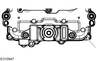
Yes DIAGNOSE the low battery voltage symptom
No INSPECT and REPAIR the DCDC case ground issue or the battery ground for corrosion.

PINPOINT TEST BS: P0A1B, P061A:92, P061A:93, P061B:64

NOTE: The Inverter System Controller (ISC) is referred to as the SOBDMC (Secondary On-Board Diagnostic Control Module C) in the scan tool.

Normal Operation and Fault Conditions

REFER to: Electric Powertrain Control - System Operation and Component Description (303-14D Electric Powertrain Control, Description and Operation).

DTC Fault Trigger Conditions

DTC Description Fault Trigger Condition
SOBDMC P0A1B:06 Drive Motor 'A' Control Module Performance: Algorithm Based Failures This DTC sets when there is an internal issue within the Inverter System Controller (ISC)
SOBDMC P061A:92 Internal Control Module Torque Performance: Performance Or Incorrect Operation This DTC sets when an internal Inverter System Controller (ISC) error is present.
SOBDMC P061A:93 Internal Control Module Torque Performance: No Operation This DTC sets when an internal Inverter System Controller (ISC) error is present.
SOBDMC P061B:64 Internal Control Module Torque Calculation Performance: Signal Plausibility Failure This DTC sets when an internal Inverter System Controller (ISC) error is present.

Possible Sources

  • Inverter System Controller (ISC) calibration
  • Inverter System Controller (ISC)
BS1 CHECK FOR INVERTER SYSTEM CONTROLLER (ISC) DIAGNOSTIC TROUBLE CODES (DTCS)
  • Ignition ON.
  • Using a diagnostic scan tool, perform the Inverter System Controller (ISC) self-test.

Are any Inverter System Controller (ISC) DTC s other than P0A1B, P061A:92, P061A:93 or P061B:64 present?
Yes DIAGNOSE all other Inverter System Controller (ISC) DTC s. REFER to the DTC chart in this section.
No GO to BS2

BS2 VERIFY THE INVERTER SYSTEM CONTROLLER (ISC) CALIBRATION LEVEL
  • Verify the Inverter System Controller (ISC) is at the latest calibration level.

Is the Inverter System Controller (ISC) at the latest calibration level?
Yes GO to BS3
No UPDATE the Inverter System Controller (ISC) to the latest calibration level.

BS3 TEST DRIVE THE VEHICLE
  • Using a diagnostic scan tool, clear the Inverter System Controller (ISC) DTC s.
  • Carry out a road test.
  • Attempt to duplicate the customer's concern.
  • Using a diagnostic scan tool, perform the Inverter System Controller (ISC) self-test.

Are DTC s P0A1B, P061A:92, P061A:93 or P061B:64 the only DTC s present in the Inverter System Controller (ISC)?
Yes INSTALL a new Inverter System Controller (ISC).
REFER to: Inverter System Controller [SOBDMC] (303-14D Electric Powertrain Control, Removal and Installation).
No DIAGNOSE all other Inverter System Controller (ISC) DTC s. REFER to the DTC chart in this section.

PINPOINT TEST BT: P0A0A:13

NOTE: The Inverter System Controller (ISC) is referred to as the SOBDMC (Secondary On-Board Diagnostic Control Module C) in the scan tool.


Refer to Wiring Diagrams Cell 12 for schematic and connector information.

Normal Operation and Fault Conditions

REFER to: Electric Powertrain Control - System Operation and Component Description (303-14D Electric Powertrain Control, Description and Operation).

DTC Fault Trigger Conditions

DTC Description Fault Trigger Condition
SOBDMC P0A0A:13 High Voltage System Interlock Circuit 'A': Circuit Open This DTC sets when a high voltage interlock circuit at the Inverter System Controller (ISC) goes open.

Possible Sources

  • Wiring, terminals or connectors
  • Inverter System Controller (ISC)

  WARNING: To prevent the risk of high-voltage shock, always follow precisely all warnings and service instructions, including instructions to depower the system. The high-voltage system utilizes approximately 300 volts DC, provided through high-voltage cables to its components and modules. The high-voltage cables and wiring are identified by orange harness tape or orange wire covering. All high-voltage components are marked with high-voltage warning labels with a high-voltage symbol. Failure to follow these instructions may result in serious personal injury or death.

NOTE: Use the correct probe adapter(s) from the Flex Probe Kit when taking measurements. Failure to use the correct probe adapter(s) may damage the connector.

BT1 REVIEW AND RECORD THE INTERLOCK DIAGNOSTIC TROUBLE CODES (DTCS)
  • Ignition ON.
  • Using a scan tool, clear all DTC s.
  • Using a scan tool, perform the Inverter System Controller (ISC) self-test and record the DTC s.

Is DTC P0A0A:13 present?
Yes GO to BT3
No The concern is not present at this time. The concern may be have been related to prior repair or service that included disconnecting the service disconnect or a high voltage cable.

BT2 INSPECT THE INVERTER SYSTEM CONTROLLER (ISC) CONNECTOR
  • Ignition OFF.
  • Depower the high voltage system.
    REFER to: High Voltage System De-energizing (414-03A High Voltage Battery, Mounting and Cables, General Procedures).
  • Check that the Inverter System Controller (ISC) C199C is fully seated.

Is the connector fully seated?
Yes GO to BT3
No Repair as necessary. CLEAR the DTC s and REPEAT the self-test.

BT3 CHECK FOR AN OPEN IN THE HIGH VOLTAGE CABLE INTERLOCK STAPLE FOR THE INVERTER SYSTEM CONTROLLER (ISC)
  • Disconnect Inverter System Controller (ISC) C199C .
  • Measure:
    Click to display connectors
    Positive Lead Measurement / Action Negative Lead
    C199C-2 C199C-3

Is the resistance less than 3 ohms?
Yes GO to BT4
No INSTALL a new (14B322) High Voltage cable assembly.

BT4 CHECK FOR CORRECT INVERTER SYSTEM CONTROLLER (ISC) OPERATION
  • Inspect Inverter System Controller (ISC) C199C interlock pins.
  • For:
    • corrosion
    • damaged or bent pins
    • pushed-out pins
  • If any concerns are present INSTALL a new (14B322) high voltage cable.
    REFER to: High Voltage Battery Cables - Hybrid Electric Vehicle (HEV) (414-03A High Voltage Battery, Mounting and Cables, Removal and Installation).
  • Reconnect the Inverter System Controller (ISC) SOBDMC connector. Make sure it seats and latches correctly.
  • Operate the system and determine if the concern is still present.

Is the concern still present?
Yes GO to BT5
No The system is operating correctly at this time. The concern may have been caused by module connections. Address the root cause of any connector or pin issues.

BT5 CHECK FOR AN OPEN IN THE HIGH VOLTAGE INTERLOCK STAPLE FOR THE INVERTER SYSTEM CONTROLLER (ISC)
  • Ignition OFF.
  • Depower the high voltage system.
    REFER to: High Voltage System De-energizing (414-03A High Voltage Battery, Mounting and Cables, General Procedures).
  • Remove the Inverter System Controller (ISC) side cover. When removing side cover, pull cover straight out approximately 2 inches before moving upwards or damage to the high voltage interlock connector may occur.
    REFER to: Inverter System Controller [SOBDMC] (303-14D Electric Powertrain Control, Removal and Installation).
  • Examine the high voltage interlock connector for damage and loose or broken conditions.
  • Measure:
    Click to display connectors
    Positive Lead Measurement / Action Negative Lead
    Inverter System Controller (ISC) side cover pin 1 Inverter System Controller (ISC) side cover pin 2

Is the resistance less than 3 ohms?
Yes GO to BT6
No INSTALL a new Inverter System Controller (ISC) side cover.

BT6 CHECK THE INVERTER SYSTEM CONTROLLER (ISC) SIDE COVER
  • Verify the seal. Check for signs of corrosion.
  • Examine all the high voltage connections for damage and loose or broken conditions.
  • Verify the high voltage terminal bolts are fully seated and torqued to 8  lb.ft ( 10.5  Nm)

Is a concern present?
Yes REPAIR as necessary
No GO to BT7

BT7 CHECK FOR INVERTER SYSTEM CONTROLLER (ISC) DIAGNOSTIC TROUBLE CODES (DTCS)
  • Install the Inverter System Controller (ISC) side cover.
    REFER to: Inverter System Controller [SOBDMC] (303-14D Electric Powertrain Control, Removal and Installation).
  • Repower the high voltage system.
    REFER to: High Voltage System De-energizing (414-03A High Voltage Battery, Mounting and Cables, General Procedures).
  • Ignition ON.
  • Using a diagnostic scan-tool, clear the DTC s.
  • Using a diagnostic scan tool, perform the Inverter System Controller (ISC) self-test.

Is Inverter System Controller (ISC) DTC P0A0A:13 present?
Yes CHECK OASIS for any applicable Technical Service Bulletins (TSBs). If a TSB exists for this concern, discontinue this test and follow TSB instructions. If no Technical Service Bulletins (TSBs) address this concern, INSTALL a new Inverter System Controller (ISC).
REFER to: Inverter System Controller [SOBDMC] (303-14D Electric Powertrain Control, Removal and Installation).
No The system is operating correctly at this time. The concern may have been caused by module connections.

PINPOINT TEST BU: U0293

NOTE: The Inverter System Controller (ISC) is referred to as the SOBDMC (Secondary On-Board Diagnostic Control Module C) in the scan tool.

Normal Operation and Fault Conditions

REFER to: Electric Powertrain Control - System Operation and Component Description (303-14D Electric Powertrain Control, Description and Operation).

DTC Fault Trigger Conditions

DTC Description Fault Trigger Condition
PCM U0293:00 Lost Communication With Hybrid/EV Powertrain Control Module 'A': No Sub Type Information This DTC sets when messages are missing from the Inverter System Controller (ISC).
BECM U0293:00 Lost Communication With Hybrid/EV Powertrain Control Module 'A': No Sub Type Information This DTC sets when messages are missing from the Inverter System Controller (ISC).
IPC U0293:00 Lost Communication With Hybrid/EV Powertrain Control Module 'A': No Sub Type Information This DTC sets when messages are missing from the Inverter System Controller (ISC).
APIM U0293:00 Lost Communication With Hybrid/EV Powertrain Control Module 'A': No Sub Type Information This DTC sets when messages are missing from the Inverter System Controller (ISC).
PAM U0293:00 Lost Communication With Hybrid/EV Powertrain Control Module 'A': No Sub Type Information This DTC sets when messages are missing from the Inverter System Controller (ISC).
BCM U0293:00 Lost Communication With Hybrid/EV Powertrain Control Module 'A': No Sub Type Information This DTC sets when messages are missing from the Inverter System Controller (ISC).
BCMC U0293:00 Lost Communication With Hybrid/EV Powertrain Control Module 'A': No Sub Type Information This DTC sets when messages are missing from the Inverter System Controller (ISC).
DCDC U0293:00 Lost Communication With Hybrid/EV Powertrain Control Module 'A': No Sub Type Information This DTC sets when messages are missing from the Inverter System Controller (ISC).

Possible Sources

  • Wiring, terminals or connectors
  • Inverter System Controller (ISC)
BU1 CARRY OUT THE NETWORK TEST

NOTE: Do not use dielectric grease in the Inverter System Controller (ISC) connector.

  • When using FDRS , the scan tool attempts to communicate with the ECM first. After establishing communication with the ECM , the scan tool then attempts to communicate with all modules on the vehicle. If an FDRS session cannot be established, FDRS may state no communication can be established with the ECM :
    • Choose No when the scan tool prompts whether or not to retry communication.
    • Enter a ECM part number, tear tag or calibration number to identify the vehicle and start a session. The ECM part number and 4- character tear tag are located on the ECM .
  • Ignition ON.

Is the Inverter System Controller (ISC) the only module offline?
Yes GO to BU3
No DIAGNOSE the network concern.
REFER to: Communications Network (418-00 Module Communications Network, Diagnosis and Testing).

BU2 UPDATE THE MODULE REPORTING U0293 TO ITS LATEST SOFTWARE LEVEL
  • Update the software of the module reporting the U0293.

Is there an updated version of software?
Yes UDPATE the software, then clear the DTCs. Repeat the module’s self-test. If DTC U0293 returns, GO to BU3 If U0293 does not return. The system is operating correctly at this time. The DTC may have been set due to outdated software.
No GO to BU3

BU3 UPDATE THE INVERTER SYSTEM CONTROLLER (ISC) SOFTWARE
  • Attempt to update the Inverter System Controller (ISC) software, regardless of whether the ISC responds to the network tool

Was the Inverter System Controller (ISC) software update successful?
Yes CLEAR the DTC s and REPEAT the self-test. If DTC U0293 returns. GO to BU4
If DTC U0293 does not return, The system is operating correctly at this time. The DTC may have been set due the software being erased.
No GO to BU4

BU4 CHECK FOR AN INTERMITTENT CONCERN

NOTE: Do not use dielectric grease in the Inverter System Controller (ISC) connector.

  • Using a diagnostic scan tool, refer to the snapshot data to determine when the fault occurs. Determine if the fault occurs during the following conditions:
    • During power-up
    • While driving
    • Temperature of vehicle
  • Attempt to duplicate the concern.

Can the fault be duplicated?
Yes GO to BU5
No The system is operating correctly at this time. The DTC may have been set due to high network traffic or an intermittent fault condition.

BU5 CHECK THE INVERTER SYSTEM CONTROLLER (ISC) VBATT CIRCUIT FOR VOLTAGE

NOTE: Do not use dielectric grease in the Inverter System Controller (ISC) connector.

  • Ignition OFF.
  • Disconnect Inverter System Controller (ISC) C199A .
  • Ignition ON.
  • Measure and record:
    Positive Lead Measurement / Action Negative Lead
      C199A-34   Ground

Is the voltage within 1.5 volts of battery voltage?
Yes GO to BU6
No With the aid of the wiring diagram, REPAIR the circuit. CLEAR the DTC s and REPEAT the self-test.

BU6 INSPECT THE GROUND CIRCUITS

NOTE: Do not use dielectric grease in the Inverter System Controller (ISC) connector.

  • Ignition OFF.
  • Disconnect and inspect ground circuits G102, G103, G104, G200 and G305 for corrosion or loose connections.

Is a concern present?
Yes Repair as necessary. CLEAR the DTC s and REPEAT the self-test.
No GO to BU7

BU7 CHECK THE INVERTER SYSTEM CONTROLLER (ISC) GROUND CIRCUITS

NOTE: Do not use dielectric grease in the Inverter System Controller (ISC) connector.

  • Ignition OFF.
  • Measure and record:
    Positive Lead Measurement / Action Negative Lead
      C199A-9   Ground
      C199A-10   Ground

Are the resistances less than 3 ohms on both pins?
Yes GO to BU8
No With the aid of the wiring diagram, REPAIR the open circuit. CLEAR the DTC s and REPEAT the self-test.

BU8 CHECK THE INVERTER SYSTEM CONTROLLER (ISC) PSR CONTROL WIRE

NOTE: Do not use dielectric grease in the Inverter System Controller (ISC) connector.

  • Measure and record:
    Positive Lead Measurement / Action Negative Lead
  • Measure and record:
    Positive Lead Measurement / Action Negative Lead
      C199A-14   Ground

Is the voltage within 1.5 volts of battery voltage?
Yes GO to BU10
No GO to BU9

BU9 CHECK THE INVERTER SYSTEM CONTROLLER (ISC) PSR CONTROL WIRE FOR AN OPEN

NOTE: Do not use dielectric grease in the Inverter System Controller (ISC) connector.

  • Ignition OFF.
  • Disconnect BCMC C1002 .
  • Ignition ON.
  • Measure and record:
    Positive Lead Measurement / Action Negative Lead
      C1002-9   C199A-14

Is the resistance less than 3 ohms?
Yes GO to BU10
No REPAIR the open circuit.

BU10 CHECK THE INVERTER SYSTEM CONTROLLER (ISC) VPWR CIRCUITS FOR A SHORT TO VOLTAGE

NOTE: Do not use dielectric grease in the Inverter System Controller (ISC) connector.

  • Measure and record:
    Positive Lead Measurement / Action Negative Lead
      C199A-39   Ground
      C199A-40   Ground

Is any voltage present?
Yes With the aid of the wiring diagram, REPAIR the short circuit. CLEAR the DTC s and REPEAT the self-test.
No GO to BU11

BU11 CHECK THE INVERTER SYSTEM CONTROLLER (ISC) VPWR CIRCUITS FOR VOLTAGE

NOTE: Do not use dielectric grease in the Inverter System Controller (ISC) connector.

  • Ignition OFF.
  • Connect a 5A fused jumper between:
    Positive Lead Measurement / Action Negative Lead
      C199A-14   Ground
  • Ignition ON.
  • Measure and record:
    Positive Lead Measurement / Action Negative Lead
      C199A-39   Ground
      C199A-40   Ground

Is the voltage within 1.5 volts of battery voltage?
Yes GO to BU12
No With the aid of the wiring diagram, REPAIR the open circuit. CLEAR the DTC s and REPEAT the self-test.

BU12 CHECK THE INVERTER SYSTEM CONTROLLER (ISC) CAN (CONTROLLER AREA NETWORK) CIRCUITS

NOTE: Do not use dielectric grease in the Inverter System Controller (ISC) connector.

  • Ignition OFF.
  • Disconnect GWM C2431 .
  • Measure and record:
    Positive Lead Measurement / Action Negative Lead
      C2431-19   C199A-11
      C2431-20   C199A-1

Is the resistance less than 5 ohms?
Yes GO to BU15
No With the aid of the wiring diagram, REPAIR the open circuit. CLEAR the DTC s and REPEAT the self-test.

BU13 CHECK THE INVERTER SYSTEM CONTROLLER (ISC) ISP-R CIRCUIT FOR VOLTAGE

NOTE: Do not use dielectric grease in the Inverter System Controller (ISC) connector.

  • Ignition ON.
  • Measure and record:
    Positive Lead Measurement / Action Negative Lead
      C199A-4   Ground

Is the voltage within 1.5 volts of battery voltage?
Yes GO to BU14
No With the aid of the wiring diagram, REPAIR the circuit. CLEAR the DTC s and REPEAT the self-test.

BU14 CHECK THE INVERTER SYSTEM CONTROLLER (ISC) WAKE UP CIRCUIT FOR VOLTAGE

NOTE: Do not use dielectric grease in the Inverter System Controller (ISC) connector.

  • Measure and record:
    Positive Lead Measurement / Action Negative Lead
      C199A-13   Ground

Is the voltage within 1.5 volts of battery voltage?
Yes GO to BU15
No With the aid of the wiring diagram, REPAIR the circuit. CLEAR the DTC s and REPEAT the self-test.

BU15 CHECK THE INVERTER SYSTEM CONTROLLER (ISC) CONNECTORS

NOTE: Do not use dielectric grease in the Inverter System Controller (ISC) connector.

  • Disconnect and inspect all the Inverter System Controller (ISC) connectors.
  • Visually inspect for:
    • Spread or loose terminals
    • Corrosion
    • Damaged, bent or pushed out pins

Is a concern present?
Yes REPAIR as necessary. CLEAR the DTC s and REPEAT the self-test.
No GO to BU16

BU16 CHECK THE INVERTER SYSTEM CONTROLLER (ISC) FOR CORRECT OPERATION

NOTE: Do not use dielectric grease in the Inverter System Controller (ISC) connector.

  • Reconnect all previously disconnected connectors and make sure they seat correctly.
  • Reconnect all the Inverter System Controller (ISC) connectors and make sure they seat and latch correctly.
  • Using a diagnostic scan-tool, clear the DTC s in the module reporting DTC U0293.
  • Using a diagnostic scan-tool, repeat the self-test.

Is DTC U0293 present?
Yes CHECK OASIS for any applicable service articles: TSB , GSB , SSM or FSA . If a service article exists for this concern, DISCONTINUE this test and FOLLOW the service article instructions. If no service articles address this concern, INSTALL a new Inverter System Controller (ISC).
REFER to: Inverter System Controller [SOBDMC] (303-14D Electric Powertrain Control, Removal and Installation).
No The system is operating correctly at this time. The DTC may have been set due to high network traffic or an intermittent fault condition.

PINPOINT TEST BV: P071A:1F, P071B, P071C

NOTE: The Inverter System Controller (ISC) is referred to as the SOBDMC (Secondary On-Board Diagnostic Control Module C) in the scan tool.

Normal Operation and Fault Conditions

REFER to: Electric Powertrain Control - System Operation and Component Description (303-14D Electric Powertrain Control, Description and Operation).

DTC Fault Trigger Conditions

DTC Description Fault Trigger Condition
SOBDMC P071A:1F Transmission Mode Switch 'A' Circuit: Circuit Intermittent This DTC sets when there is an intermittent concern with the EV mode switch or wiring from the switch to the Inverter System Controller (ISC).
SOBDMC P071B:00 Transmission Mode Switch 'A' Circuit Low: No Sub Type Information This DTC sets when a short to ground is detected in the circuit from the switch to the Inverter System Controller (ISC). The Inverter System Controller (ISC) can also set this DTC if the customer were to press the EV mode button down for prolonged period (several minutes).
SOBDMC P071C:00 Transmission Mode Switch 'A' Circuit High: No Sub Type Information This DTC sets when a short to power is detected in the circuit from the EV mode switch to the Inverter System Controller (ISC).

Possible Sources

  • Wiring, terminals or connectors
  • EV mode button pressed for a prolonged period (several minutes).
BV1 VERIFY THE CUSTOMER CONCERN

NOTE: This DTC will not clear without a key cycle.

  • Confirm with the customer the EV Mode Switch was not pressed down for an extended period of time or an object was placed on the button (such as a box or bag).

Was the EV Mode Switch pressed for an extended period of time?
Yes Inform the customer not to press the EV Mode Switch for an extended period of time. CLEAR the DTC s and REPEAT the self-test.
No GO to BV2

BV2 CHECK THE EV MODE SWITCH CIRCUITS FOR AN OPEN
  • Ignition OFF.
  • Disconnect Instrument Panel Console Switch Assembly C3010 .
  • Disconnect Inverter System Controller (ISC) C199A .
  • Measure and record:
    Positive Lead Measurement / Action Negative Lead
      C3010-11   C199A-33
      C3010-4   C199A-24

Is the resistance below 5 ohms?
Yes GO to BV3
No With the aid of the wiring diagram, REPAIR the open circuit. CLEAR the DTC s and REPEAT the self-test.

BV3 CHECK THE EV MODE SWITCH CIRCUITS FOR A SHORT TO GROUND
  • Measure and record:
    Positive Lead Measurement / Action Negative Lead
      C199A-33   Ground
      C199A-24   Ground

Is the resistance above 10K ohms?
Yes GO to BV4
No With the aid of the wiring diagram, REPAIR the open circuit. CLEAR the DTC s and REPEAT the self-test.

BV4 CHECK THE EV MODE SWITCH CIRCUITS FOR A SHORT TO VOLTAGE
  • Ignition ON.
  • Measure and record:
    Positive Lead Measurement / Action Negative Lead
      C199A-33   Ground
      C199A-24   Ground

Is any voltage present?
Yes With the aid of the wiring diagram, REPAIR the short circuit. CLEAR the Inverter System Controller (ISC) DTC s and REPEAT the self-test.
No GO to BV5

BV5 CHECK THE EV MODE SWITCH CIRCUITS FOR A SHORT TOGETHER
  • Ignition OFF.
  • Measure and record:
    Positive Lead Measurement / Action Negative Lead
      C199A-33   C199A-24

Is the resistance greater than 10K ohms?
Yes GO to BV6
No With the aid of the wiring diagram, REPAIR the short circuit. CLEAR the Inverter System Controller (ISC) DTC s and REPEAT the self-test.

BV6 CHECK THE EV MODE SWITCH OPERATION
  • Connect Instrument Panel Console Switch Assembly C3010 .
  • Ignition ON.
  • Measure and record:
    Positive Lead Measurement / Action Negative Lead
      C199A-33   C199A-24

Is the resistance between 27K and 39K ohms with the EV mode button not pressed?
Yes GO to BV7
No INSTALL a new EV mode switch.

BV7 CHECK THE EV MODE SWITCH OPERATION
  • Have an assistant press the EV mode button.
  • Measure and record:
    Positive Lead Measurement / Action Negative Lead
      C199A-33   C199A-24

Is the resistance less than 5 ohms with the EV mode switch button pressed?
Yes GO to BV8
No INSTALL a new EV mode switch.

BV8 CHECK FOR CORRECT INVERTER SYSTEM CONTROLLER (ISC) OPERATION
  • Ignition OFF.
  • Disconnect and inspect all Inverter System Controller (ISC) connectors.
  • Repair:
    • corrosion (install new connector or terminals – clean module pins)
    • damaged or bent pins – install new terminals/pins
    • pushed-out pins – install new pins as necessary
  • Reconnect the Inverter System Controller (ISC) connectors. Make sure they seat and latch correctly.
  • Ignition ON.
  • Clear the Inverter System Controller (ISC) DTC s.
  • Press and hold the EV mode button for 1 second, 5 times in a row.
  • Using a diagnostic scan tool, perform the Inverter System Controller (ISC) self-test.

Is DTC P071A, P071B or P071C set in the Inverter System Controller (ISC)?
Yes CHECK OASIS for any applicable service articles: TSB , GSB , SSM or FSA . If a service article exists for this concern, DISCONTINUE this test and FOLLOW the service article instructions. If no service articles address this concern, with the aid of the wiring diagram inspect for intermittent circuit concerns related to the EV mode switch and Inverter System Controller (ISC). VERIFY all of the inline connectors from the EV mode switch and Inverter System Controller (ISC) are seated and latched correctly.
If no intermittent circuit concerns related to the EV mode switch and Inverter System Controller (ISC) are found, INSTALL a new EV mode switch.
No The system is operating correctly at this time. The concern may have been caused by module connections. ADDRESS the root cause of any connector or pin issues.

PINPOINT TEST BW: P0726:62

NOTE: The Inverter System Controller (ISC) is referred to as the SOBDMC (Secondary On-Board Diagnostic Control Module C) in the scan tool.

Normal Operation and Fault Conditions

REFER to: Electric Powertrain Control - System Operation and Component Description (303-14D Electric Powertrain Control, Description and Operation).

DTC Fault Trigger Conditions

DTC Description Fault Trigger Condition
SOBDMC P0726:62 Engine Speed Input Circuit Range/Performance: Signal Compare Failure This DTC sets when a CKP fault is detected while the engine is running.

Possible Sources

  • CKP sensor/wiring
  • CMP sensor/wiring
  • Wiring, terminals or connectors
  • ECM
BW1 CHECK FOR ECM (ENGINE CONTROL MODULE) DIAGNOSTIC TROUBLE CODES (DTCS)
  • Ignition ON.
  • Using a diagnostic scan tool, perform the ECM self-test.

Are any CKP or CMP DTC s present in the ECM ?
Yes DIAGNOSE CKP or CMP DTC s. Refer to the appropriate section in Group 303 for the procedure.
No GO to BW2

BW2 CHECK FOR INVERTER SYSTEM CONTROLLER (ISC) DIAGNOSTIC TROUBLE CODES (DTCS)
  • Ignition ON.
  • Using a diagnostic scan tool, perform the Inverter System Controller (ISC) self-test.

Is DTC P1A0C present in the Inverter System Controller (ISC)?
Yes DIAGNOSE DTC P1A0C GO to Pinpoint Test CU
No GO to BW3

BW3 CHECK THE CLEAN TACHOMETER OUTPUT (CTO) CIRCUIT FOR AN OPEN
  • Ignition OFF.
  • Disconnect Inverter System Controller (ISC) C199A .
  • Disconnect ECM C1381B .
  • Measure:
    Positive Lead Measurement / Action Negative Lead
      C199A-2   C1381B-69

Is the resistance below 5 ohms?
Yes GO to BW4
No With the aid of the wiring diagram, REPAIR the open circuit.

BW4 CHECK THE CLEAN TACHOMETER OUTPUT (CTO) CIRCUIT FOR A SHORT TO GROUND
  • Measure:
    Positive Lead Measurement / Action Negative Lead
      C199A-2   Ground

Is the resistance greater than 10K ohms?
Yes GO to BW5
No With the aid of the wiring diagram, REPAIR the short circuit.

BW5 CHECK THE CLEAN TACHOMETER OUTPUT (CTO) CIRCUIT FOR A SHORT TO VOLTAGE
  • Ignition ON.
  • Measure:
    Positive Lead Measurement / Action Negative Lead
      C199A-2   Ground

Is any voltage present?
Yes With the aid of the wiring diagram, REPAIR the short circuit.
No GO to BW6

BW6 CHECK THE CKP (CRANKSHAFT POSITION) SENSOR CIRCUITS FOR AN OPEN
  • Ignition OFF.
  • Disconnect CKP C101 .
  • Disconnect ECM C1381E .
  • Measure and record:
    Positive Lead Measurement / Action Negative Lead
      C101-1   C1381E-11
      C101-2   C1381E-60
      C101-3   C1381E-59

Is the resistance below 5 ohms?
Yes GO to BW7
No With the aid of the wiring diagram, REPAIR the open circuit.

BW7 CHECK THE CKP (CRANKSHAFT POSITION) SENSOR CIRCUITS FOR A SHORT TO GROUND
  • Measure and record:
    Positive Lead Measurement / Action Negative Lead
      C1381E-11   Ground
      C1381E-60   Ground
      C1381E-59   Ground

Is the resistance above 10K ohms?
Yes GO to BW8
No With the aid of the wiring diagram, REPAIR the open circuit.

BW8 CHECK THE CKP (CRANKSHAFT POSITION) SENSOR CIRCUITS FOR A SHORT TO VOLTAGE
  • Ignition ON.
  • Measure and record:
    Positive Lead Measurement / Action Negative Lead
      C1381E-11   Ground
      C1381E-60   Ground
      C1381E-59   Ground

Is any voltage present?
Yes With the aid of the wiring diagram, REPAIR the short circuit. CLEAR the Inverter System Controller (ISC) DTC s and REPEAT the self-test.
No GO to BW9

BW9 CHECK THE CMP (CAMSHAFT POSITION) SENSOR CIRCUITS FOR AN OPEN
  • Ignition OFF.
  • Disconnect CMP C1366 .
  • Measure and record:
    Positive Lead Measurement / Action Negative Lead
      C1366-1   C1381E-45
      C1366-2   C1381E-44
      C1366-3   C1381E-17

Is the resistance below 5 ohms?
Yes GO to BW10
No With the aid of the wiring diagram, REPAIR the open circuit.

BW10 CHECK THE CMP (CAMSHAFT POSITION) SENSOR CIRCUITS FOR A SHORT TO GROUND
  • Measure and record:
    Positive Lead Measurement / Action Negative Lead
      C1381E-45   Ground
      C1381E-44   Ground
      C1381E-17   Ground

Is the resistance above 10K ohms?
Yes GO to BW11
No With the aid of the wiring diagram, REPAIR the open circuit.

BW11 CHECK THE CMP (CAMSHAFT POSITION) SENSOR CIRCUITS FOR A SHORT TO VOLTAGE
  • Ignition ON.
  • Measure and record:
    Positive Lead Measurement / Action Negative Lead
      C1381E-45   Ground
      C1381E-44   Ground
      C1381E-17   Ground

Is any voltage present?
Yes With the aid of the wiring diagram, REPAIR the short circuit. CLEAR the Inverter System Controller (ISC) DTC s and REPEAT the self-test.
No GO to BW12

BW12 CHECK THE INVERTER SYSTEM CONTROLLER (ISC) DIAGNOSTIC TROUBLE CODES (DTCS)
  • Reconnect all previously disconnected connectors.
  • Ignition ON.
  • CLEAR the Inverter System Controller (ISC) DTC s.
  • Start the engine.
  • Force the engine on (apply accelerator in park).
  • Ignition OFF.
  • Ignition ON.
  • Using a diagnostic scan tool, run the Inverter System Controller (ISC) self-test.

Is DTC P0726:62 present?
Yes
REFER to: Powertrain Control Module (PCM) Input and Output Controls (303-14C Electronic Engine Controls, Diagnosis and Testing).
Pinpoint Test Z.
No The system is operating correctly at this time. The concern may have been caused by module connections. ADDRESS the root cause of any connector or pin issues.

PINPOINT TEST BX: P0C2F:71, P088E, P0E4E

NOTE: The Inverter System Controller (ISC) is referred to as the SOBDMC (Secondary On-Board Diagnostic Control Module C) in the scan tool.

Normal Operation and Fault Conditions

REFER to: Electric Powertrain Control - System Operation and Component Description (303-14D Electric Powertrain Control, Description and Operation).

DTC Fault Trigger Conditions

DTC Description Fault Trigger Condition
SOBDMC P0C2F:71 Internal Control Module Drive Motor/Generator-Engine Speed Sensor Performance: Actuator Stuck This DTC sets when an internal error occurs or a speed sensor DTC is present.
SOBDMC P088E:00 Planetary Gear Set Failure: No Sub Type Information This DTC sets when an issue is detected with the main planetary gearset.
SOBDMC P0E4E:00 Engine Failed to Crank: No Sub Type Information This DTC sets if the engine is locked.

Possible Sources

  • Engine concern
  • Transmission concern
BX1 CHECK THE INVERTER SYSTEM CONTROLLER (ISC) CALIBRATION LEVEL
  • Verify the Inverter System Controller (ISC) is at the latest calibration level.

Is the Inverter System Controller (ISC) at the latest calibration level?
Yes GO to BX2
No UPDATE the Inverter System Controller (ISC) to the latest calibration level.

BX2 ATTEMPT TO TURN THE ENGINE OVER

NOTE: Turn the engine clockwise only, using the crankshaft bolt.

  • Accessory ON.
  • Place the vehicle in Neutral Tow mode with the following steps:
    • Press the menu button on the controls on the steering wheel.
    • Select Settings.
    • Select Neutral Tow.
    • Follow the instructions on the information display.
    • Fully press the brake pedal.
  • Select NEUTRAL.
  • Ignition OFF.
  • Depower the high voltage system.
    REFER to: High Voltage System De-energizing (414-03A High Voltage Battery, Mounting and Cables, General Procedures).
  • With the vehicle in Neutral Tow mode and the key off, position the vehicle on a hoist.
    REFER to: Jacking and Lifting - Overview (100-02 Jacking and Lifting, Description and Operation).
  • Using a suitable tool, manually turn the engine.

Does the engine turn freely?
Yes GO to BX3
No
REFER to: Engine (303-01C Engine, Diagnosis and Testing).

BX3 CHECK IF THE WHEELS ARE ROTATING
  • Using a suitable tool, manually turn the engine.

Are any of the wheels rotating as you turn the engine over?
Yes INSTALL a new transmission.
REFER to: Transmission (307-01B Automatic Transmission - Automatic Transmission – HF45, Removal and Installation).
CLEAR the Inverter System Controller (ISC) DTC s. REPEAT the self-test.
No GO to BX4

BX4 MOVE THE VEHICLE
  • Lower the vehicle.
  • While still in Neutral Tow mode with the key off, push the vehicle backward and forward two feet in each direction.

Does the engine spin when the wheels are turned or is excessive mechanical noise heard from the transmission area?
Yes INSTALL a new transmission.
REFER to: Transmission (307-01B Automatic Transmission - Automatic Transmission – HF45, Removal and Installation).
CLEAR the Inverter System Controller (ISC) DTC s. REPEAT the self-test.
No GO to BX5

BX5 CHECK THE TRANSMISSION FLUID CONDITION
  • Check the transmission fluid for any debris.
    REFER to: Transmission Fluid Level Check (307-01B Automatic Transmission - Automatic Transmission – HF45, General Procedures).

Is any excessive debris or contamination is present?
Yes INSTALL a new transmission.
REFER to: Transmission (307-01B Automatic Transmission - Automatic Transmission – HF45, Removal and Installation).
CLEAR the Inverter System Controller (ISC) DTC s. REPEAT the self-test.
No GO to BX6

BX6 CHECK THE ENGINE OIL CONDITION
  • Check engine oil for excessive gasoline contamination.

Is there excessive gasoline contamination in the engine oil?
Yes DIAGNOSE the fuel injector leakage/ stuck-on concern.
REFER to: Engine (303-01C Engine, Diagnosis and Testing).
No GO to BX7

BX7 TEST DRIVE THE VEHICLE
  • Repower the high voltage system.
    REFER to: High Voltage System De-energizing (414-03A High Voltage Battery, Mounting and Cables, General Procedures).
  • Test drive the vehicle listening for any excessive noise.

Is any excessive noise present during the test drive?
Yes DIAGNOSE the mechanical noise issue.
REFER to: Engine (303-01C Engine, Diagnosis and Testing).
No CHECK OASIS for any applicable service articles: TSB , GSB , SSM or FSA . If a service article exists for this concern, DISCONTINUE this test and FOLLOW the service article instructions. If no service articles address this concern,
REFER to: Powertrain Control Module (PCM) Input and Output Controls (303-14C Electronic Engine Controls, Diagnosis and Testing).
Pinpoint Test Z.

PINPOINT TEST BY: P0A2B, P0A2C, P0A2D

NOTE: The Inverter System Controller (ISC) is referred to as the SOBDMC (Secondary On-Board Diagnostic Control Module C) in the scan tool.

Normal Operation and Fault Conditions

REFER to: Electric Powertrain Control - System Operation and Component Description (303-14D Electric Powertrain Control, Description and Operation).

DTC Fault Trigger Conditions

DTC Description Fault Trigger Condition
SOBDMC P0A2B:64 Drive Motor 'A' Temperature Sensor 'A' Circuit Range/Performance: Signal Plausibility Failure This DTC sets when the motor coil temperature sensor reading does not correlate with the generator coil temperature sensor and TFT sensor readings.
SOBDMC P0A2C:00 Drive Motor 'A' Temperature Sensor 'A' Circuit Low: No Sub Type Information This DTC sets when a short to ground is detected in the motor coil temperature circuit.
SOBDMC P0A2D:00 Drive Motor 'A' Temperature Sensor 'A' Circuit High: No Sub Type Information This DTC sets when an open circuit is detected in the motor coil temperature circuit.

Possible Sources

  • Wiring, terminals or connectors
  • Transmission concern
  • Inverter System Controller (ISC) calibration
BY1 CHECK THE INVERTER SYSTEM CONTROLLER (ISC) CALIBRATION LEVEL

NOTE: DTC P0A2B can set due to external aftermarket engine block heater. In such cases the P0A2B can be ignored.

  • Verify the Inverter System Controller (ISC) is at the latest calibration level.

Is the Inverter System Controller (ISC) at the latest calibration level?
Yes GO to BY2
No UPDATE the Inverter System Controller (ISC) to the latest calibration level.

BY2 CHECK FOR APPLICABLE SERVICE ARTICLES
  • Check OASIS for any applicable service articles: TSB , GSB , SSM or FSA .

Are any service articles applicable to the concern?
Yes DISCONTINUE this test and FOLLOW the service article instructions.
No GO to BY3

BY3 CHECK THE AUTOMATIC TRANSMISSION FLUID LEVEL

NOTE: A low automatic transmission fluid level may cause a traction motor over temperature condition.

  • Verify the automatic transmission fluid level and condition is correct.
    REFER to: Transmission Fluid Level Check (307-01B Automatic Transmission - Automatic Transmission – HF45, General Procedures).

Is the transmission fluid level and condition correct?
Yes GO to BY7
No DIAGNOSE the transmission cooling concern.
REFER to: Automatic Transmission (307-01B Automatic Transmission - Automatic Transmission – HF45, Diagnosis and Testing).

BY4 CHECK THE AUTOMATIC TRANSMISSION PARAMETER IDENTIFICATIONS (PIDS)

NOTE: A low automatic transmission fluid level may cause a traction motor over temperature condition.

  • Cold soak the vehicle at ambient temperature for at least 4 hours.
  • Access the  SOBDMC  and monitor the  TFT (Deg C)  PID

  • Access the  SOBDMC  and monitor the  MCLTEMP (Deg C)  PID


Are the PID s within 15°C (27°F) of each other?
Yes GO to BY5
No GO to BY7

BY5 INTERMITTENT CHECK
  • Access the  SOBDMC  and monitor the  TFT (Deg C)  PID

  • Access the  SOBDMC  and monitor the  MCLTEMP (Deg C)  PID

  • While observing the PID s carry out the following:
    • Lightly tap on the transmission assembly connector and wiggle the accessible harness from the transmission assembly to the Inverter System Controller (ISC)
    • Wiggle the transmission assembly connector
    • Look for sudden changes in temperature when the harness and connectors are wiggled

Are any concerns present?
Yes REPAIR as necessary. CLEAR the Inverter System Controller (ISC) DTC s. REPEAT the self-test.
No GO to BY6

BY6 VISUAL INSPECTION OF THE INVERTER SYSTEM CONTROLLER (ISC) CONNECTORS
  • Ignition OFF.
  • Disconnect and inspect all Inverter System Controller (ISC) connectors.
  • Repair:
    • corrosion (install new connector or terminals – clean module pins)
    • damaged or bent pins – install new terminals/pins
    • pushed-out pins – install new pins as necessary
    • water intrusion – install new connector
  • Reconnect the Inverter System Controller (ISC) connectors. Make sure they seat and latch correctly.
  • Test drive and bring the vehicle to operating temperature.
  • CLEAR the Inverter System Controller (ISC) DTC s.
  • Using a diagnostic scan tool, run the Inverter System Controller (ISC) self-test.

Is DTC P0A2B, P0A2C or P0A2D present?
Yes GO to BY7
No The system is operating correctly at this time. The DTC may have been set due to high network traffic or an intermittent fault condition.

BY7 CHECK THE MOTOR TEMPERATURE SENSOR CIRCUITS FOR AN OPEN
  • Ignition OFF.
  • Disconnect HF45 Transmission C1111 .
  • Disconnect Inverter System Controller (ISC) C199B .
  • Measure:
    Positive Lead Measurement / Action Negative Lead
      C199B-11   C1111-35
      C199B-10   C1111-25

Is the resistance less than 3 ohms?
Yes GO to BY8
No With the aid of the wiring diagram, REPAIR the open circuit.
CLEAR the Inverter System Controller (ISC) DTC s. REPEAT the self-test.

BY8 CHECK THE MOTOR TEMPERATURE CIRCUITS FOR A SHORT TOGETHER
  • Ignition OFF.
  • Measure:
    Positive Lead Measurement / Action Negative Lead
      C1111-35 C1111-1 all pins except pin 25

Is the resistance greater than 10K ohms?
Yes GO to BY9
No With the aid of the wiring diagram, REPAIR the short circuit.
CLEAR the Inverter System Controller (ISC) DTC s. REPEAT the self-test

BY9 CHECK THE MOTOR TEMPERATURE SIGNAL CIRCUIT FOR A SHORT TO VOLTAGE
  • Ignition OFF.
  • Measure:
    Positive Lead Measurement / Action Negative Lead
      C1111-35   Ground

Is any voltage present?
Yes With the aid of the wiring diagram, REPAIR the short circuit.
CLEAR the Inverter System Controller (ISC) DTC s. REPEAT the self-test
No GO to BY10

BY10 CHECK THE MOTOR TEMPERATURE RETURN CIRCUIT FOR A SHORT TO VOLTAGE
  • Measure:
    Positive Lead Measurement / Action Negative Lead
      C1111-25   Ground

Is any voltage present?
Yes With the aid of the wiring diagram, REPAIR the short circuit.
CLEAR the Inverter System Controller (ISC) DTC s. REPEAT the self-test
No GO to BY11

BY11 CHECK THE MOTOR TEMPERATURE SIGNAL CIRCUIT FOR A SHORT TO GROUND
  • Ignition OFF.
  • Measure:
    Positive Lead Measurement / Action Negative Lead
      C1111-35   Ground

Is the resistance greater than 10K ohms?
Yes GO to BY12
No With the aid of the wiring diagram, REPAIR the short circuit.
CLEAR the Inverter System Controller (ISC) DTC s. REPEAT the self-test

BY12 CHECK THE MOTOR TEMPERATURE RETURN CIRCUIT FOR A SHORT TO GROUND
  • Measure:
    Positive Lead Measurement / Action Negative Lead
      C1111-25   Ground

Is the resistance greater than 10K ohms?
Yes GO to BY13
No With the aid of the wiring diagram, REPAIR the short circuit.
CLEAR the Inverter System Controller (ISC) DTC s. REPEAT the self-test

BY13 CHECK THE MOTOR TEMPERATURE SENSOR RESISTANCE
  • Measure and record:
    Positive Lead Measurement / Action Negative Lead
    C1111 pin 25, component side C1111 pin 35, component side
  • Record the measurement result and compare with the expected temperature values below:
    • -40 °F ( -40 °C) 1695.776 K ohms - 2302.415 K ohms
    • -31 °F ( -35 °C) 1194.043 K ohms - 1598.148 K ohms
    • -22 °F ( -30 °C) 852.9844 K ohms - 1126.096 K ohms
    • -13 °F ( -25 °C) 617.6642 K ohms - 804.7572 K ohms
    • -4 °F ( -20 °C) 453.0069 K ohms - 582.8025 K ohms
    • 5 °F ( -15 °C) 336.2607 K ohms - 427.3758 K ohms
    • 14 °F ( -10 °C) 252.446 K ohms - 317.117 K ohms
    • 23 °F ( -5 °C) 191.5609 K ohms - 237.9395 K ohms
    • 32 °F ( °C) 146.8371 K ohms - 180.419 K ohms
    • 41 °F ( 5 °C) 113.637 K ohms - 138.172 K ohms
    • 50 °F ( 10 °C) 88.743 K ohms - 106.82 K ohms
    • 59 °F ( 15 °C) 69.9003 K ohms - 83.3236 K ohms
    • 68 °F ( 20 °C) 55.5087 K ohms - 65.5487 K ohms
    • 77 °F ( 25 °C) 44.4225 K ohms - 51.9824 K ohms
    • 86 °F ( 30 °C) 35.8128 K ohms - 41.5406 K ohms
    • 95 °F ( 35 °C) 29.0745 K ohms - 33.4388 K ohms
    • 104 °F ( 40 °C) 23.7617 K ohms - 27.1044 K ohms

Is the resistance within specification?
Yes GO to BY14
No INSTALL a new transmission.
REFER to: Transmission (307-01B Automatic Transmission - Automatic Transmission – HF45, Removal and Installation).
CLEAR the Inverter System Controller (ISC) DTC s. REPEAT the self-test.

BY14 CHECK THE MOTOR TEMPERATURE SENSORS FOR A SHORT TO GROUND
  • Measure and record:
    Positive Lead Measurement / Action Negative Lead
    C1111 pin 25, component side   Ground
    C1111 pin 35, component side   Ground

Is the resistance greater than 10K ohms?
Yes GO to BY15
No INSTALL a new transmission.
REFER to: Transmission (307-01B Automatic Transmission - Automatic Transmission – HF45, Removal and Installation).
CLEAR the Inverter System Controller (ISC) DTC s. REPEAT the self-test.

BY15 VISUAL INSPECTION OF THE INVERTER SYSTEM CONTROLLER (ISC) CONNECTORS
  • Ignition OFF.
  • Disconnect and inspect all Inverter System Controller (ISC) connectors.
  • Repair:
    • corrosion (install new connector or terminals – clean module pins)
    • damaged or bent pins – install new terminals/pins
    • pushed-out pins – install new pins as necessary
    • water intrusion – install new connector
  • Reconnect the Inverter System Controller (ISC) connectors. Make sure they seat and latch correctly.
  • Ignition ON.
  • CLEAR the Inverter System Controller (ISC) DTC s.
  • Carefully wiggle all accessible wiring and connectors associated with the Inverter System Controller (ISC).
  • Test drive and bring the vehicle to operating temperature.
  • Using a diagnostic scan tool, run the Inverter System Controller (ISC) self-test.

Is DTC P0A2B, P0A2C or P0A2D present?
Yes CHECK OASIS for any applicable service articles: TSB , GSB , SSM or FSA . If a service article exists for this concern, DISCONTINUE this test and FOLLOW the service article instructions. If no service articles address this concern, INSTALL a new low voltage harness between the Inverter System Controller (ISC) and the transmission.
CLEAR the Inverter System Controller (ISC) DTC s and repeat the self-test.
No The system is operating correctly at this time. The DTC may have been set due to high network traffic or an intermittent fault condition.

PINPOINT TEST BZ: P0A3F, P0C50

NOTE: The Inverter System Controller (ISC) is referred to as the SOBDMC (Secondary On-Board Diagnostic Control Module C) in the scan tool.

Normal Operation and Fault Conditions

REFER to: Electric Powertrain Control - System Operation and Component Description (303-14D Electric Powertrain Control, Description and Operation).

DTC Fault Trigger Conditions

DTC Description Fault Trigger Condition
SOBDMC P0A3F:00 Drive Motor 'A' Position Sensor Circuit: No Sub Type Information This DTC sets when a resolver wiring concern is detected.
SOBDMC P0C50:00 Drive Motor 'A' Position Sensor Circuit 'A': No Sub Type Information This DTC sets when a wiring concern in the harness between the Inverter System Controller (ISC) and the transmission is detected.

Possible Sources

  • Wiring, terminals or connectors
  • Transmission assembly
BZ1 CHECK FOR INVERTER SYSTEM CONTROLLER (ISC) DTC (DIAGNOSTIC TROUBLE CODE) P0C51

NOTE: Wiring overlays or repinning of circuits are NOT appropriate for DTCs P0A3F or P0C50 due to risk of hardware damage.

  • Ignition ON.
  • Using a diagnostic scan tool, run the Inverter System Controller (ISC) self-test.

Was DTC P0C51 read from the Inverter System Controller (ISC)?
Yes GO to Pinpoint Test Z
No GO to BZ2

BZ2 CHECK THE INVERTER SYSTEM CONTROLLER (ISC) CALIBRATION LEVEL
  • Verify the Inverter System Controller (ISC) is at the latest calibration level.

Is the Inverter System Controller (ISC) at the latest calibration level?
Yes GO to BZ3
No UPDATE the Inverter System Controller (ISC) to the latest calibration level.

BZ3 VISUAL INSPECTION OF THE LOW VOLTAGE SYSTEM
  • Ignition OFF.
  • Depower the high voltage system.
    REFER to: High Voltage System De-energizing (414-03A High Voltage Battery, Mounting and Cables, General Procedures).
  • Visually inspect all the low voltage cables.
  • Make sure all the low voltage connectors are correctly and securely connected and latched.
  • Examine all the low voltage cables and connectors for damaged, burned or overheated insulation and loose or broken conditions.

Is a concern present?
Yes REPAIR as necessary. CLEAR the Inverter System Controller (ISC) DTC s and REPEAT the self-test.
No GO to BZ4

BZ4 CHECK FOR INVERTER SYSTEM CONTROLLER (ISC) DIAGNOSTIC TROUBLE CODES (DTCS)
  • Ignition ON.
  • Using a diagnostic scan tool, run the Inverter System Controller (ISC) self-test.

Was DTC P0C55, P0C57, P0C58, P0C52 or P0C53 read from the Inverter Sy stem Controller (ISC)?
Yes For P0C55 GO to Pinpoint Test CJ
For P0C57 GO to Pinpoint Test CK
For P0C58 GO to Pinpoint Test CL
For P0C52 GO to Pinpoint Test CH
For P0C53 GO to Pinpoint Test CI
No GO to BZ5

BZ5 CHECK THE MOTOR RESOLVER RESISTANCE
  • Disconnect HF 45 Transmission C1111 .
  • Disconnect Inverter System Controller (ISC) C199B .
  • Measure and record:
    Positive Lead Measurement / Action Negative Lead
    HF45 Transmission C1111 pin 1, component side HF45 Transmission C1111 pin 11, component side

Is the resistance between 7.6 and 11.4 ohms?
Yes GO to BZ6
No INSTALL a new Transmission.
REFER to: Transmission (307-01B Automatic Transmission - Automatic Transmission – HF45, Removal and Installation).
CLEAR the Inverter System Controller (ISC) DTC s. REPEAT the self-test.

BZ6 CHECK THE MOTOR RESOLVER RESISTANCE
  • Measure and record:
    Positive Lead Measurement / Action Negative Lead
    HF45 Transmission C1111 pin 3, component side HF45 Transmission C1111 pin 13, component side

Is the resistance between 11.6 and 17.4 ohms?
Yes GO to BZ7
No INSTALL a new Transmission.
REFER to: Transmission (307-01B Automatic Transmission - Automatic Transmission – HF45, Removal and Installation).
CLEAR the Inverter System Controller (ISC) DTC s. REPEAT the self-test.

BZ7 CHECK THE MOTOR RESOLVER RESISTANCE
  • Measure and record:
    Positive Lead Measurement / Action Negative Lead
    HF45 Transmission C1111 pin 2, component side HF45 Transmission C1111 pin 12, component side

Is the resistance between 11.2 and 16.8 ohms?
Yes GO to BZ8
No INSTALL a new Transmission.
REFER to: Transmission (307-01B Automatic Transmission - Automatic Transmission – HF45, Removal and Installation).
CLEAR the Inverter System Controller (ISC) DTC s. REPEAT the self-test.

BZ8 CHECK THE MOTOR RESOLVER MS2 CIRCUIT FOR A SHORT
  • Measure and record:
    Positive Lead Measurement / Action Negative Lead
    C1111 pin 13, component side C1111 all pins except pin 3, component side

Is the resistance greater than 10K ohms?
Yes GO to BZ9
No INSTALL a new transmission.
REFER to: Transmission (307-01B Automatic Transmission - Automatic Transmission – HF45, Removal and Installation).
CLEAR the Inverter System Controller (ISC) DTC s. REPEAT the self-test.

BZ9 CHECK THE MOTOR RESOLVER MS1 CIRCUIT FOR A SHORT
  • Measure and record:
    Positive Lead Measurement / Action Negative Lead
    C1111 pin 12, component side C1111 all pins except pin 2, component side

Is the resistance greater than 10K ohms?
Yes GO to BZ10
No INSTALL a new transmission.
REFER to: Transmission (307-01B Automatic Transmission - Automatic Transmission – HF45, Removal and Installation).
CLEAR the Inverter System Controller (ISC) DTC s. REPEAT the self-test.

BZ10 CHECK THE MOTOR RESOLVER MR2 CIRCUIT FOR A SHORT
  • Measure and record:
    C1111 pin 11, component side C1111 all pins except pin 1, component side

Is the resistance greater than 10K ohms?
Yes GO to BZ11
No INSTALL a new transmission.
REFER to: Transmission (307-01B Automatic Transmission - Automatic Transmission – HF45, Removal and Installation).
CLEAR the Inverter System Controller (ISC) DTC s. REPEAT the self-test.

BZ11 CHECK THE MOTOR RESOLVER SENSOR FOR A SHORT TO GROUND
  • Measure and record:
    Positive Lead Measurement / Action Negative Lead
    C1111 pin 13, component side   Ground
    C1111 pin 3, component side   Ground
    C1111 pin 12, component side   Ground
    C1111 pin 2, component side   Ground
    C1111 pin 1, component side   Ground
    C1111 pin 11, component side   Ground

Is the resistance greater than 10K ohms?
Yes GO to BZ12
No INSTALL a new transmission.
REFER to: Transmission (307-01B Automatic Transmission - Automatic Transmission – HF45, Removal and Installation).
CLEAR the Inverter System Controller (ISC) DTC s. REPEAT the self-test.

BZ12 CHECK THE MOTOR RESOLVER HARNESS CIRCUITS FOR AN OPEN
  • Measure and record:
    Positive Lead Measurement / Action Negative Lead
      C1111-13   C199B-1
      C1111-3   C199B-2
      C1111-12   C199B-7
      C1111-2   C199B-8
      C1111-1   C199B-13
      C1111-11   C199B-19

Is the resistance less than 3 ohms?
Yes GO to BZ13
No With the aid of the wiring diagram REPAIR the open circuit.
CLEAR the Inverter System Controller (ISC) DTC s. REPEAT the self-test.

BZ13 CHECK THE MOTOR RESOLVER HARNESS CIRCUITS FOR A SHORT TOGETHER
  • Measure and record:
    Positive Lead Measurement / Action Negative Lead
      C1111-13   C1111-3
      C1111-13   C1111-12
      C1111-13   C1111-2
      C1111-13   C1111-1
      C1111-13   C1111-11
      C1111-3   C1111-12
      C1111-3   C1111-2
      C1111-3   C1111-1
      C1111-3   C1111-11
      C1111-12   C1111-2
      C1111-12   C1111-1
      C1111-12   C1111-11
      C1111-2   C1111-1
      C1111-2   C1111-11
      C1111-1   C1111-11

Is the resistance greater than 10K ohms?
Yes GO to BZ14
No With the aid of the wiring diagram, REPAIR the short circuit. CLEAR the Inverter System Controller (ISC) DTC s. REPEAT the self-test.

BZ14 CHECK THE MOTOR RESOLVER HARNESS CIRCUITS FOR A SHORT TO GROUND
  • Measure and record:
    Positive Lead Measurement / Action Negative Lead
      C1111-13   Ground
      C1111-3   Ground
      C1111-12   Ground
      C1111-2   Ground
      C1111-1   Ground
      C1111-11   Ground

Is the resistance above 10K ohms?
Yes GO to BZ15
No With the aid of the wiring diagram, REPAIR the open circuit.

BZ15 CHECK THE MOTOR RESOLVER HARNESS CIRCUITS FOR A SHORT TO VOLTAGE
  • Ignition ON.
  • Measure and record:
    Positive Lead Measurement / Action Negative Lead
      C1111-13   Ground
      C1111-3   Ground
      C1111-12   Ground
      C1111-2   Ground
      C1111-1   Ground
      C1111-11   Ground

Is any voltage present?
Yes With the aid of the wiring diagram, REPAIR the short circuit. CLEAR the Inverter System Controller (ISC) DTC s and REPEAT the self-test.
No GO to BZ16

BZ16 CHECK THE MOTOR RESOLVER CIRCUITS FOR A SHORT TO THE EXTERNAL CABLE SHIELD
  • Ignition OFF.
  • Measure and record:
    Positive Lead Measurement / Action Negative Lead
      C199B-1   C199B-9
      C199B-2   C199B-9
      C199B-7   C199B-9
      C199B-8   C199B-9
      C199B-13   C199B-9
      C199B-19   C199B-9

Is the resistance more than 10,000 ohms?
Yes GO to BZ17
No With the aid of the wiring diagram, REPAIR the short circuit. CLEAR the Inverter System Controller (ISC) DTC s. REPEAT the self-test.

BZ17 CHECK FOR CORRECT INVERTER SYSTEM CONTROLLER (ISC) OPERATION
  • Ignition OFF.
  • Disconnect and inspect all Inverter System Controller (ISC) connectors.
  • Repair:
    • corrosion (install new connector or terminals – clean module pins)
    • damaged or bent pins – install new terminals/pins
    • pushed-out pins – install new pins as necessary
  • Reconnect the Inverter System Controller (ISC) connectors. Make sure they seat and latch correctly.
  • Connect HF45 Transmission C1111 .
  • Ignition ON.
  • Ignition OFF.
  • Wait 5 minutes.
  • Ignition ON.
  • Clear the Inverter System Controller (ISC) DTC s
  • Ignition OFF.
  • Start the engine.
  • Using a diagnostic scan tool, run the Inverter System Controller (ISC) self-test.

Is the concern still present?
Yes GO to BZ18
No The system is operating correctly at this time. The concern may have been caused by module connections. ADDRESS the root cause of any connector or pin issues.

BZ18 CHECK FOR APPLICABLE SERVICE ARTICLES
  • CHECK OASIS for any applicable service articles: TSB , GSB , SSM or FSA .

Was a service article found?
Yes DISCONTINUE this test and FOLLOW the service article instructions.
No
REFER to: Powertrain Control Module (PCM) Input and Output Controls (303-14C Electronic Engine Controls, Diagnosis and Testing).
Pinpoint Test Z.

PINPOINT TEST CA: P0A44:92

NOTE: The Inverter System Controller (ISC) is referred to as the SOBDMC (Secondary On-Board Diagnostic Control Module C) in the scan tool.

Normal Operation and Fault Conditions

REFER to: Electric Powertrain Control - System Operation and Component Description (303-14D Electric Powertrain Control, Description and Operation).

DTC Fault Trigger Conditions

DTC Description Fault Trigger Condition
SOBDMC P0A44:92 Drive Motor 'A' Position Sensor Circuit Overspeed: Performance Or Incorrect Operation This DTC sets when an intermittent resolver wiring concern is detected or when an attempt at heavy acceleration with the vehicles wheels are in the air, such as on a hoist has occurred .

Possible Sources

  • Wiring, terminals or connectors
  • Transmission assembly
CA1 CHECK FOR INVERTER SYSTEM CONTROLLER (ISC) MOTOR POSITION DIAGNOSTIC TROUBLE CODES (DTCS)

NOTE: Wiring overlays or repinning of circuits are NOT appropriate for DTC P0A44 due to risk of hardware damage.

  • Ignition ON.
  • Using a diagnostic scan tool, run the Inverter System Controller (ISC) self-test.

Are any motor position DTC s present?
Yes DIAGNOSE all other motor position DTC s, REFER to the DTC chart in this section.
No GO to CA2

CA2 REVIEW THE SNAPSHOT DATA FOR DTC (DIAGNOSTIC TROUBLE CODE) P0A44:92
  • Using a diagnostic scan tool, review the DTC snapshot data for DTC P0A44:92.

Was the DTC set at a high rate of speed (over 100 mph)?
Yes The system is operating correctly at this time. This DTC is expected to set in cases where the driver lost traction at extreme speeds.
CLEAR the Inverter System Controller (ISC) DTC s. REPEAT the self-test.
No GO to CA3

CA3 TEST DRIVE THE VEHICLE
  • Using a diagnostic scan tool, clear the Inverter System Controller (ISC) DTC s.
  • Access the  SOBDMC  and monitor the  M_SPEED (Rpm)  PID

  • Attempt to reproduce the concern by fast acceleration and braking. While monitoring the PID , look for intermittent or erratic behavior.

Did the PID display any erratic behavior during the test drive?
Yes GO to Pinpoint Test BZ
No CHECK OASIS for any applicable service articles: TSB , GSB , SSM or FSA . If a service article exists for this concern, DISCONTINUE this test and FOLLOW the service article instructions. If no service articles address this concern,
REFER to: Powertrain Control Module (PCM) Input and Output Controls (303-14C Electronic Engine Controls, Diagnosis and Testing).
Pinpoint Test Z.

PINPOINT TEST CB: P0A5D, P0A60, P0A63, P0A6F, P0A72, P0A75, P0E52

NOTE: The Inverter System Controller (ISC) is referred to as the SOBDMC (Secondary On-Board Diagnostic Control Module C) in the scan tool.

Normal Operation and Fault Conditions

REFER to: Electric Powertrain Control - System Operation and Component Description (303-14D Electric Powertrain Control, Description and Operation).

DTC Fault Trigger Conditions

DTC Description Fault Trigger Condition
SOBDMC P0A5D:00 Drive Motor 'A' Phase U Current: No Sub Type Information This DTC sets when an internal issue with the Inverter System Controller (ISC) is detected.
SOBDMC P0A60:00 Drive Motor 'A' Phase V Current: No Sub Type Information This DTC sets when an internal issue with the Inverter System Controller (ISC) is detected.
SOBDMC P0A63:00 Drive Motor 'A' Phase W Current: No Sub Type Information This DTC sets when an internal issue with the Inverter System Controller (ISC) is detected.
SOBDMC P0A6F:00 Generator Phase U Current: No Sub Type Information This DTC sets when the U current sensor offset is greater than the calibrated threshold.
SOBDMC P0A72:00 Generator Phase V Current: No Sub Type Information This DTC sets when the V current sensor offset is greater than the calibrated threshold.
SOBDMC P0A75:00 Generator Phase W Current: No Sub Type Information This DTC sets when the W current sensor offset is greater than the calibrated threshold.
SOBDMC P0E52:00 DC/DC Converter Current Sensor 'A' Circuit Range/Performance: No Sub Type Information This DTC sets if the inductor current sensor offset is higher than a calibrated range.

Possible Sources

  • Inverter System Controller (ISC)
CB1 CHECK THE INVERTER SYSTEM CONTROLLER (ISC) CALIBRATION LEVEL
  • Verify the Inverter System Controller (ISC) is at the latest calibration level.

Is the Inverter System Controller (ISC) at the latest calibration level?
Yes GO to CB2
No UPDATE the Inverter System Controller (ISC) to the latest calibration level.

CB2 CHECK INVERTER SYSTEM CONTROLLER (ISC) DIAGNOSTIC TROUBLE CODES (DTCS)
  • Using a diagnostic scan tool, perform the Inverter System Controller (ISC) self-test.

Are DTC s P0A5D, P0A60, P0A63, P0A6F, P0A72, P0A75 or P0E52 present?
Yes CHECK OASIS for any applicable service articles: TSB , GSB , SSM or FSA . If a service article exists for this concern, DISCONTINUE this test and FOLLOW the service article instructions. If no service articles address this concern, INSTALL a new Inverter System Controller (ISC).
REFER to: Inverter System Controller [SOBDMC] (303-14D Electric Powertrain Control, Removal and Installation).
No The system is operating correctly at this time. The DTC may have been set due to high network traffic or an intermittent fault condition.

PINPOINT TEST CC: P0A5F, P0A62, P0A65

NOTE: The Inverter System Controller (ISC) is referred to as the SOBDMC (Secondary On-Board Diagnostic Control Module C) in the scan tool.

Normal Operation and Fault Conditions

REFER to: Electric Powertrain Control - System Operation and Component Description (303-14D Electric Powertrain Control, Description and Operation).

DTC Fault Trigger Conditions

DTC Description Fault Trigger Condition
SOBDMC P0A5F:00 Drive Motor 'A' Phase U Current High: No Sub Type Information This DTC sets when an excessive current condition is detected.
SOBDMC P0A62:00 Drive Motor 'A' Phase V Current High: No Sub Type Information This DTC sets when an excessive current condition is detected.
SOBDMC P0A65:00 Drive Motor 'A' Phase W Current High: No Sub Type Information This DTC sets when an excessive current condition is detected.

Possible Sources

  • Wiring, terminals or connectors
  • Low voltage wiring
  • Other Inverter System Controller (ISC) DTC s
  • Inverter System Controller (ISC) calibration
  • TRID block programming
  • Transmission assembly
CC1 CHECK THE INVERTER SYSTEM CONTROLLER (ISC) DIAGNOSTIC TROUBLE CODES (DTCS)
  • Using a diagnostic scan tool, retrieve the Inverter System Controller (ISC) CMDTC s.

Are any Inverter System Controller (ISC) DTC s other than P0A5F, P0A62 or P0A65 present?
Yes DIAGNOSE all other Inverter System Controller (ISC) DTC s. REFER to the DTC chart in this section.
No GO to CC2

CC2 CHECK THE INVERTER SYSTEM CONTROLLER (ISC) CALIBRATION LEVEL
  • Verify the Inverter System Controller (ISC) is at the latest calibration level.

Is the Inverter System Controller (ISC) at the latest calibration level?
Yes GO to CC3
No UPDATE the Inverter System Controller (ISC) to the latest calibration level.

CC3 VERIFY THE INVERTER SYSTEM CONTROLLER (ISC) TRID BLOCK HAS BEEN PROGRAMMED CORRECTLY
  • Verify the Inverter System Controller (ISC) TRID block has been programmed correctly. Refer to Module Reprogramming on the scan tool.

Has the TRID block been successfully programmed?
Yes GO to CC4
No CHECK OASIS for any applicable service articles: TSB , GSB , SSM or FSA . If a service article exists for this concern, DISCONTINUE this test and FOLLOW the service article instructions. If no service articles address this concern, reflash the Inverter System Controller (ISC) TRID block.

CC4 VISUAL INSPECTION OF THE LOW VOLTAGE SYSTEM
  • Ignition OFF.
  • Depower the high voltage system.
    REFER to: High Voltage System De-energizing (414-03A High Voltage Battery, Mounting and Cables, General Procedures).
  • Visually inspect all the low voltage cables.
  • Make sure all the low voltage connectors are correctly and securely connected.
  • Examine all the low voltage cables and connectors for damaged, burned or overheated insulation and loose or broken conditions.

Is a concern present?
Yes REPAIR as necessary. CLEAR the Inverter System Controller (ISC) DTC s and REPEAT the self-test.
No GO to CC5

CC5 CHECK THE MOTOR RESOLVER CIRCUITS FOR AN OPEN
  • Ignition OFF.
  • Disconnect HF 45 Transmission C1111 .
  • Disconnect Inverter System Controller (ISC) C199B .
  • Measure and record:
    Positive Lead Measurement / Action Negative Lead
      C1111-13   C199B-1
      C1111-3   C199B-2
      C1111-12   C199B-7
      C1111-2   C199B-8
      C1111-1   C199B-13
      C1111-11   C199B-19

Is the resistance less than 5 ohms?
Yes GO to CC6
No INSTALL a new High Voltage Cable from the Inverter System Controller (ISC) to the traction battery.
REFER to: High Voltage Battery Cables - Hybrid Electric Vehicle (HEV) (414-03A High Voltage Battery, Mounting and Cables, Removal and Installation).
. CLEAR the Inverter System Controller (ISC) DTC s. REPEAT the self-test.

CC6 CHECK THE MOTOR RESOLVER CIRCUITS FOR A SHORT TO GROUND
  • Measure and record:
    Positive Lead Measurement / Action Negative Lead
      C1111-13   Ground
      C1111-3   Ground
      C1111-12   Ground
      C1111-2   Ground
      C1111-1   Ground
      C1111-11   Ground

Is the resistance above 10K ohms?
Yes GO to CC7
No With the aid of the wiring diagram, REPAIR the open circuit.

CC7 CHECK THE MOTOR RESOLVER CIRCUITS FOR A SHORT TO VOLTAGE
  • Ignition ON.
  • Measure and record:
    Positive Lead Measurement / Action Negative Lead
      C1111-13   Ground
      C1111-3   Ground
      C1111-12   Ground
      C1111-2   Ground
      C1111-1   Ground
      C1111-11   Ground

Is any voltage present?
Yes With the aid of the wiring diagram, REPAIR the short circuit. CLEAR the Inverter System Controller (ISC) DTC s and REPEAT the self-test.
No GO to CC8

CC8 CHECK THE MOTOR RESOLVER CIRCUITS FOR A SHORT TO THE EXTERNAL CABLE SHIELD
  • Ignition OFF.
  • Measure and record:
    Positive Lead Measurement / Action Negative Lead
      C199B-1   C199B-9
      C199B-2   C199B-9
      C199B-7   C199B-9
      C199B-8   C199B-9
      C199B-13   C199B-9
      C199B-19   C199B-9

Is the resistance less than 5 ohms?
Yes GO to CC9
No With the aid of the wiring diagram, REPAIR the short circuit. CLEAR the Inverter System Controller (ISC) DTC s. REPEAT the self-test.

CC9 CHECK THE MOTOR RESOLVER CIRCUITS FOR A SHORT TOGETHER
  • Measure and record:
    Positive Lead Measurement / Action Negative Lead
      C1111-13   C1111-3
      C1111-13   C1111-12
      C1111-13   C1111-2
      C1111-13   C1111-1
      C1111-13   C1111-11
      C1111-3   C1111-12
      C1111-3   C1111-2
      C1111-3   C1111-1
      C1111-3   C1111-11
      C1111-12   C1111-2
      C1111-12   C1111-1
      C1111-12   C1111-11
      C1111-2   C1111-1
      C1111-2   C1111-11
      C1111-1   C1111-11

Is the resistance greater than 10K ohms?
Yes GO to CC10
No INSTALL a new Transmission.
REFER to: Transmission (307-01B Automatic Transmission - Automatic Transmission – HF45, Removal and Installation).
CLEAR the Inverter System Controller (ISC) DTC s. REPEAT the self-test.

CC10 CHECK THE MOTOR RESOLVER FOR A SHORT TOGETHER
  • Measure and record:
    Positive Lead Measurement / Action Negative Lead
    C1111 pin 13, component side C1111 pin 3, component side
    C1111 pin 13, component side C1111 pin 12, component side
    C1111 pin 13, component side C1111 pin 2, component side
    C1111 pin 13, component side C1111 pin 1, component side
    C1111 pin 13, component side C1111 pin 11, component side
    C1111 pin 3, component side C1111 pin 12, component side
    C1111 pin 3, component side C1111 pin 2, component side
    C1111 pin 3, component side C1111 pin 1, component side
    C1111 pin 3, component side C1111 pin 11, component side
    C1111 pin 12, component side C1111 pin 2, component side
    C1111 pin 12, component side C1111 pin 1, component side
    C1111 pin 12, component side C1111 pin 11, component side
    C1111 pin 2, component side C1111 pin 1, component side
    C1111 pin 2, component side C1111 pin 11, component side
    C1111 pin 1, component side C1111 pin 11, component side

Is the resistance greater than 10K ohms?
Yes GO to CC11
No With the aid of the wiring diagram, REPAIR the short circuit. CLEAR the Inverter System Controller (ISC) DTC s. REPEAT the self-test.

CC11 CHECK THE MOTOR RESOLVER RESISTANCE
  • Measure and record:
    Positive Lead Measurement / Action Negative Lead
    HF45 Transmission C1111 pin 1, component side HF45 Transmission C1111 pin 11, component side

Is the resistance between 7.6 and 11.4 ohms?
Yes GO to CC12
No INSTALL a new Transmission.
REFER to: Transmission (307-01B Automatic Transmission - Automatic Transmission – HF45, Removal and Installation).
CLEAR the Inverter System Controller (ISC) DTC s. REPEAT the self-test.

CC12 CHECK THE MOTOR RESOLVER RESISTANCE
  • Measure and record:
    Positive Lead Measurement / Action Negative Lead
    HF45 Transmission C1111 pin 3, component side HF45 Transmission C1111 pin 13, component side

Is the resistance between 11.6 and 17.4 ohms?
Yes GO to CC13
No INSTALL a new Transmission.
REFER to: Transmission (307-01B Automatic Transmission - Automatic Transmission – HF45, Removal and Installation).
CLEAR the Inverter System Controller (ISC) DTC s. REPEAT the self-test.

CC13 CHECK THE MOTOR RESOLVER RESISTANCE
  • Measure and record:
    Positive Lead Measurement / Action Negative Lead
    HF45 Transmission C1111 pin 2, component side HF45 Transmission C1111 pin 12, component side

Is the resistance between 11.2 and 16.8 ohms?
Yes GO to CC14
No INSTALL a new Transmission.
REFER to: Transmission (307-01B Automatic Transmission - Automatic Transmission – HF45, Removal and Installation).
CLEAR the Inverter System Controller (ISC) DTC s. REPEAT the self-test.

CC14 CHECK THE MOTOR RESOLVER SENSOR FOR A SHORT TO GROUND
  • Measure and record:
    Positive Lead Measurement / Action Negative Lead
    C1111 pin 1, component side   Ground
    C1111 pin 2, component side   Ground
    C1111 pin 3, component side   Ground
    C1111 pin 11, component side   Ground
    C1111 pin 12, component side   Ground
    C1111 pin 13, component side   Ground

Is the resistance greater than 10K ohms?
Yes GO to CC15
No INSTALL a new transmission.
REFER to: Transmission (307-01B Automatic Transmission - Automatic Transmission – HF45, Removal and Installation).
CLEAR the Inverter System Controller (ISC) DTC s. REPEAT the self-test.

CC15 VISUAL INSPECTION OF THE HIGH VOLTAGE SYSTEM
  • Ignition OFF.
  • Depower the high voltage system.
    REFER to: High Voltage System De-energizing (414-03A High Voltage Battery, Mounting and Cables, General Procedures).
  • Remove the Inverter System Controller (ISC) side cover. When removing side cover, pull cover straight out approximately 2 inches before moving upwards or damage to the high voltage interlock connector may occur.
    REFER to: Inverter System Controller [SOBDMC] (303-14D Electric Powertrain Control, Removal and Installation).
  • Examine all the high voltage connections for damage and loose or broken conditions.
  • Verify the high voltage terminal bolts are fully seated and torqued to 8  lb.ft ( 10.5  Nm)

Is a concern present?
Yes REPAIR as necessary. CLEAR the Inverter System Controller (ISC) DTC s and REPEAT the self-test.
No GO to CC16

CC16 CHECK FOR EXCESSIVE PHASE RESISTANCE
  • Measure and record:
    Positive Lead Measurement / Action Negative Lead
    ISC/SOBDMC pin 3, component side ISC/SOBDMC pin 4, component side
    ISC/SOBDMC pin 3, component side ISC/SOBDMC pin 5, component side
    ISC/SOBDMC pin 4, component side ISC/SOBDMC pin 5, component side

Is the resistance less than 5 ohms?
Yes GO to CC17
No INSTALL a new Transmission.
REFER to: Transmission (307-01B Automatic Transmission - Automatic Transmission – HF45, Removal and Installation).
CLEAR the Inverter System Controller (ISC) DTC s. REPEAT the self-test.

CC17 CHECK FOR MOTOR PHASES FOR A SHORT TO GROUND
  • Measure and record:
    Positive Lead Measurement / Action Negative Lead
    ISC/SOBDMC pin 3, component side   Ground
    ISC/SOBDMC pin 4, component side   Ground
    ISC/SOBDMC pin 5, component side   Ground

Is the resistance greater than 10K ohms?
Yes GO to CC18
No INSTALL a new Transmission.
REFER to: Transmission (307-01B Automatic Transmission - Automatic Transmission – HF45, Removal and Installation).
CLEAR the Inverter System Controller (ISC) DTC s. REPEAT the self-test.

CC18 CHECK FOR CORRECT INVERTER SYSTEM CONTROLLER (ISC) OPERATION
  • Ignition OFF.
  • Disconnect and inspect all Inverter System Controller (ISC) connectors.
  • Repair:
    • corrosion (install new connector or terminals – clean module pins)
    • damaged or bent pins – install new terminals/pins
    • pushed-out pins – install new pins as necessary
  • Reconnect all Inverter System Controller (ISC) connectors. Make sure they seat and latch correctly.
  • Install the Inverter System Controller (ISC) side cover.
  • Connect HF45 Transmission C1111 .
  • Ignition ON.
  • CLEAR the Inverter System Controller (ISC) DTC s.
  • Ignition OFF.
  • Wait 60 seconds.
  • Start the engine.
  • Using a diagnostic scan tool, run the Inverter System Controller (ISC) self-test.

Is DTC P0A5F, P0A62 or P0A65 still present?
Yes INSTALL a new Transmission.
REFER to: Transmission (307-01B Automatic Transmission - Automatic Transmission – HF45, Removal and Installation).
CLEAR the Inverter System Controller (ISC) DTC s. REPEAT the self-test.
No The system is operating correctly at this time. The concern may have been caused by module connections. ADDRESS the root cause of any connector or pin issues.

PINPOINT TEST CD: P0A7D

NOTE: The Inverter System Controller (ISC) is referred to as the SOBDMC (Secondary On-Board Diagnostic Control Module C) in the scan tool.

Normal Operation and Fault Conditions

REFER to: Electric Powertrain Control - System Operation and Component Description (303-14D Electric Powertrain Control, Description and Operation).

DTC Fault Trigger Conditions

DTC Description Fault Trigger Condition
SOBDMC P0A7D:00 Hybrid/EV Battery Pack State of Charge Low: No Sub Type Information The Inverter System Controller (ISC) is not allowed to charge the high voltage battery if the gear selector is left in NEUTRAL. This DTC sets when the battery state of charge falls below a calibrated threshold while the gear selector is in NEUTRAL and the Inverter System Controller (ISC) shuts down the vehicle to conserve energy.

Possible Sources

  • Inverter System Controller (ISC)
  • Customer usage
CD1 CHECK FOR INVERTER SYSTEM CONTROLLER (ISC) DIAGNOSTIC TROUBLE CODES (DTCS)
  • Ignition ON.
  • Using a diagnostic scan tool, run the Inverter System Controller (ISC) self-test.

Is DTC s P0A7D:00 the only DTC read from the Inverter System Controller (ISC)?
Yes Inform the customer not to leave the vehicle in NEUTRAL for an extended period of time. Doing so will not allow the HV battery to charge and will eventually get discharged.
No DIAGNOSE all other Inverter System Controller (ISC) DTC s, REFER to the DTC chart in this section.

PINPOINT TEST CE: P0A94

NOTE: The Inverter System Controller (ISC) is referred to as the SOBDMC (Secondary On-Board Diagnostic Control Module C) in the scan tool.

Normal Operation and Fault Conditions

REFER to: Electric Powertrain Control - System Operation and Component Description (303-14D Electric Powertrain Control, Description and Operation).

DTC Fault Trigger Conditions

DTC Description Fault Trigger Condition
SOBDMC P0A94:00 DC/DC Converter 'A' Performance: No Sub Type Information This DTC sets when an internal issue with inductor current sensor (not serviceable) is detected.

Possible Sources

  • Inverter System Controller (ISC) calibration
  • Transmission assembly
  • Inverter System Controller (ISC)
CE1 CHECK THE INVERTER SYSTEM CONTROLLER (ISC) CALIBRATION LEVEL
  • Verify the Inverter System Controller (ISC) is at the latest calibration level.

Is the Inverter System Controller (ISC) at the latest calibration level?
Yes GO to CE2
No UPDATE the Inverter System Controller (ISC) to the latest calibration level.

CE2 TEST DRIVE THE VEHICLE
  • Clear the Inverter System Controller (ISC) DTC s.
  • Drive the vehicle at speeds above 45 mph & aggressive acceleration in an attempt to duplicate the concern
  • Using a diagnostic scan tool, run the Inverter System Controller (ISC) self-test.

Is DTC P0A94 present?
Yes If the vehicle exhibits noticeably decreased performance compared to a similarly equipped vehicle or exhibits noticeably increased engine speed flares (different than a similarly equipped vehicle), INSTALL a new Transmission.
REFER to: Transmission (307-01B Automatic Transmission - Automatic Transmission – HF45, Removal and Installation).
CLEAR the Inverter System Controller (ISC) DTC s. REPEAT the self-test.
If the vehicle performance is comparable to a similarly equipped vehicle, CHECK OASIS for any applicable service articles: TSB , GSB , SSM or FSA . If a service article exists for this concern, DISCONTINUE this test and FOLLOW the service article instructions. If no service articles address this concern, INSTALL a new Inverter System Controller (ISC).
REFER to: Inverter System Controller [SOBDMC] (303-14D Electric Powertrain Control, Removal and Installation).
No GO to CE3

CE3 CHECK THE VEHICLE SERVICE HISTORY
  • CHECK the vehicle service history for recent service actions related to the Inverter System Controller (ISC).

Has the Inverter System Controller (ISC) been recently been replaced for DTC s P0A7A:96 or P0A78:96?
Yes INSTALL a new Transmission.
REFER to: Transmission (307-01B Automatic Transmission - Automatic Transmission – HF45, Removal and Installation).
CLEAR the Inverter System Controller (ISC) DTC s. REPEAT the self-test.
No
REFER to: Powertrain Control Module (PCM) Input and Output Controls (303-14C Electronic Engine Controls, Diagnosis and Testing).
Pinpoint Test Z.

PINPOINT TEST CF: P0C00

NOTE: The Inverter System Controller (ISC) is referred to as the SOBDMC (Secondary On-Board Diagnostic Control Module C) in the scan tool.

Normal Operation and Fault Conditions

REFER to: Electric Powertrain Control - System Operation and Component Description (303-14D Electric Powertrain Control, Description and Operation).

DTC Fault Trigger Conditions

DTC Description Fault Trigger Condition
SOBDMC P0C00:00 Drive Motor 'A' Current Low: No Sub Type Information This DTC sets when the 3 phase motor current is not within the expected range or when the resolver circuitry is incorrectly wired.

Possible Sources

  • Wiring, terminals or connectors
  • Transmission assembly
CF1 CHECK FOR INVERTER SYSTEM CONTROLLER (ISC) DIAGNOSTIC TROUBLE CODES (DTCS)
  • Ignition ON.
  • Using a diagnostic scan tool, run the Inverter System Controller (ISC) self-test.

Are DTC s P0A3F or P0C50 set in the Inverter System Controller (ISC)?
Yes GO to Pinpoint Test BZ
No GO to CF2

CF2 CHECK THE INVERTER SYSTEM CONTROLLER (ISC) CALIBRATION LEVEL
  • Verify the Inverter System Controller (ISC) is at the latest calibration level.

Is the Inverter System Controller (ISC) at the latest calibration level?
Yes GO to CF3
No UPDATE the Inverter System Controller (ISC) to the latest calibration level.

CF3 VISUAL INSPECTION OF THE HIGH VOLTAGE SYSTEM
  • Ignition OFF.
  • Depower the high voltage system.
    REFER to: High Voltage System De-energizing (414-03A High Voltage Battery, Mounting and Cables, General Procedures).
  • Remove the Inverter System Controller (ISC) side cover. When removing side cover, pull cover straight out approximately 2 inches before moving upwards or damage to the high voltage interlock connector may occur.
    REFER to: Inverter System Controller [SOBDMC] (303-14D Electric Powertrain Control, Removal and Installation).
  • Examine all the high voltage connections for damage and loose or broken conditions.
  • Verify the high voltage terminal bolts are fully seated and torqued to 8  lb.ft ( 10.5  Nm)

Is a concern present?
Yes REPAIR as necessary. CLEAR the Inverter System Controller (ISC) DTC s and REPEAT the self-test.
No GO to CF4

CF4 CHECK FOR MOTOR PHASE CONTINUITY
  • Measure and record:
    Positive Lead Measurement / Action Negative Lead
    ISC/SOBDMC pin 3, component side ISC/SOBDMC pin 4, component side
    ISC/SOBDMC pin 3, component side ISC/SOBDMC pin 5, component side
    ISC/SOBDMC pin 4, component side ISC/SOBDMC pin 5, component side

Is the resistance less than 5 ohms?
Yes GO to CF5
No INSTALL a new Transmission.
REFER to: Transmission (307-01B Automatic Transmission - Automatic Transmission – HF45, Removal and Installation).
CLEAR the Inverter System Controller (ISC) DTC s. REPEAT the self-test.

CF5 CHECK FOR MOTOR PHASE SHORT TO GROUND
  • Measure and record:
    Positive Lead Measurement / Action Negative Lead
    ISC/SOBDMC pin 3, component side   Ground
    ISC/SOBDMC pin 4, component side   Ground
    ISC/SOBDMC pin 5, component side   Ground

Is the resistance greater than 10K ohms?
Yes GO to CF6
No INSTALL a new Transmission.
REFER to: Transmission (307-01B Automatic Transmission - Automatic Transmission – HF45, Removal and Installation).
CLEAR the Inverter System Controller (ISC) DTC s. REPEAT the self-test.

CF6 CHECK THE MOTOR RESOLVER HARNESS CIRCUITS FOR AN OPEN
  • Disconnect HF 45 Transmission C1111 .
  • Disconnect Inverter System Controller (ISC) C199B .
  • Measure and record:
    Positive Lead Measurement / Action Negative Lead
      C1111-13   C199B-1
      C1111-3   C199B-2
      C1111-12   C199B-7
      C1111-2   C199B-8
      C1111-1   C199B-13
      C1111-11   C199B-19

Is the resistance less than 3 ohms?
Yes GO to CF7
No With the aid of the wiring diagram REPAIR the open circuit.
CLEAR the Inverter System Controller (ISC) DTC s. REPEAT the self-test.

CF7 CHECK FOR CORRECT INVERTER SYSTEM CONTROLLER (ISC) OPERATION
  • Ignition OFF.
  • Disconnect and inspect all Inverter System Controller (ISC) connectors.
  • Repair:
    • corrosion (install new connector or terminals – clean module pins)
    • damaged or bent pins – install new terminals/pins
    • pushed-out pins – install new pins as necessary
  • Reconnect the Inverter System Controller (ISC) connectors. Make sure they seat and latch correctly.
  • Install the Inverter System Controller (ISC) side cover.
  • Repower the high voltage system.
    REFER to: High Voltage System De-energizing (414-03A High Voltage Battery, Mounting and Cables, General Procedures).
  • Ignition ON.
  • CLEAR the Inverter System Controller (ISC) DTC s.
  • Ignition OFF.
  • Wait 5 minutes.
  • Ignition ON.
  • Using a diagnostic scan tool, run the Inverter System Controller (ISC) self-test.

Is DTC P0C00 still present?
Yes INSTALL a new Transmission.
REFER to: Transmission (307-01B Automatic Transmission - Automatic Transmission – HF45, Removal and Installation).
CLEAR the Inverter System Controller (ISC) DTC s. REPEAT the self-test.
No The system is operating correctly at this time. The concern may have been caused by module connections. ADDRESS the root cause of any connector or pin issues.

PINPOINT TEST CG: P0C19

NOTE: The Inverter System Controller (ISC) is referred to as the SOBDMC (Secondary On-Board Diagnostic Control Module C) in the scan tool.

Normal Operation and Fault Conditions

REFER to: Electric Powertrain Control - System Operation and Component Description (303-14D Electric Powertrain Control, Description and Operation).

DTC Fault Trigger Conditions

DTC Description Fault Trigger Condition
SOBDMC P0C19:00 Drive Motor 'A' Torque Delivered Performance: No Sub Type Information This DTC sets as a tattle-tale for other DTC s. There will always be another DTC set with this DTC .

Possible Sources

  • Related DTC s
CG1 CHECK FOR INVERTER SYSTEM CONTROLLER (ISC) DIAGNOSTIC TROUBLE CODES (DTCS)
  • Using a diagnostic scan tool, perform the Inverter System Controller (ISC) self-test.

Are any Inverter System Controller (ISC) DTC s other than P0C19:00 present?
Yes DIAGNOSE all other Inverter System Controller (ISC) DTC s, REFER to the DTC chart in this section.
No GO to CG2

CG2 INSPECT THE INVERTER SYSTEM CONTROLLER (ISC) CONNECTORS
  • Ignition OFF.
  • Disconnect and inspect all Inverter System Controller (ISC) connectors for:
    • corrosion
    • damaged or bent pins
    • pushed-out pins

Is a concern present?
Yes REPAIR as necessary. CLEAR the DTC s and REPEAT the self-test.
No The system is operating correctly at this time. The DTC may have been set due to high network traffic or an intermittent fault condition.

PINPOINT TEST CH: P0C52

NOTE: The Inverter System Controller (ISC) is referred to as the SOBDMC (Secondary On-Board Diagnostic Control Module C) in the scan tool.

Normal Operation and Fault Conditions

REFER to: Electric Powertrain Control - System Operation and Component Description (303-14D Electric Powertrain Control, Description and Operation).

DTC Fault Trigger Conditions

DTC Description Fault Trigger Condition
SOBDMC P0C52:00 Drive Motor 'A' Position Sensor Circuit 'A' Low: No Sub Type Information This DTC sets when a wiring concern in the harness between the Inverter System Controller (ISC) and the transmission is detected.

Possible Sources

  • Inverter System Controller (ISC) calibration
  • Wiring, terminals or connectors
  • Transmission assembly
CH1 CHECK THE INVERTER SYSTEM CONTROLLER (ISC) CALIBRATION LEVEL

NOTE: Wiring overlays or repinning of circuits are NOT appropriate for DTC P0C52 due to risk of hardware damage.

  • Verify the Inverter System Controller (ISC) is at the latest calibration level.

Is the Inverter System Controller (ISC) at the latest calibration level?
Yes GO to CH2
No UPDATE the Inverter System Controller (ISC) to the latest calibration level.

CH2 CHECK FOR INVERTER SYSTEM CONTROLLER (ISC) CMDTC (CONTINUOUS MEMORY DIAGNOSTIC TROUBLE CODE) P0C52
  • Ignition ON.
  • Using a diagnostic scan tool, check for CMDTC s.

Was CMDTC P0C52 set in the Inverter System Controller (ISC)?
Yes GO to CH3
No The system is operating correctly at this time. The DTC may have been set due to high network traffic or an intermittent fault condition.

CH3 VISUAL INSPECTION OF THE LOW VOLTAGE SYSTEM
  • Ignition OFF.
  • Depower the high voltage system.
    REFER to: High Voltage System De-energizing (414-03A High Voltage Battery, Mounting and Cables, General Procedures).
  • Visually inspect all the low voltage cables.
  • Make sure all the low voltage connectors are correctly and securely connected.
  • Examine all the low voltage cables and connectors for damaged, burned or overheated insulation and loose or broken conditions.

Is a concern present?
Yes REPAIR as necessary. CLEAR the Inverter System Controller (ISC) DTC s and REPEAT the self-test.
No GO to CH4

CH4 CHECK THE MS1 CIRCUIT FOR A SHORT TO GROUND
  • Ignition OFF.
  • Disconnect HF 45 Transmission C1111 .
  • Disconnect Inverter System Controller (ISC) C199B .
  • Measure and record:
    Positive Lead Measurement / Action Negative Lead
      C1111-12   Ground

Is the resistance above 10K ohms?
Yes GO to CH5
No With the aid of the wiring diagram, REPAIR the short circuit. CLEAR the Inverter System Controller (ISC) DTC s. REPEAT the self-test.

CH5 CHECK THE MS3 CIRCUIT FOR A SHORT TO GROUND
  • Measure and record:
    Positive Lead Measurement / Action Negative Lead
      C1111-2   Ground

Is the resistance above 10K ohms?
Yes GO to CH6
No With the aid of the wiring diagram, REPAIR the short circuit. CLEAR the Inverter System Controller (ISC) DTC s. REPEAT the self-test.

CH6 CHECK FOR CORRECT INVERTER SYSTEM CONTROLLER (ISC) OPERATION
  • Ignition OFF.
  • Disconnect and inspect all Inverter System Controller (ISC) connectors.
  • Repair:
    • corrosion (install new connector or terminals – clean module pins)
    • damaged or bent pins – install new terminals/pins
    • pushed-out pins – install new pins as necessary
  • Reconnect the Inverter System Controller (ISC) connectors. Make sure they seat and latch correctly.
  • Connect HF 45 Transmission C1111 .
  • Ignition ON.
  • Operate the system and determine if the concern is still present.

Is the concern still present?
Yes CHECK OASIS for any applicable service articles: TSB , GSB , SSM or FSA . If a service article exists for this concern, DISCONTINUE this test and FOLLOW the service article instructions. If no service articles address this concern, GO to Pinpoint Test BZ (In step CA4 continue through to step CA5 regardless of DTC presence.)
No The system is operating correctly at this time. The concern may have been caused by module connections. ADDRESS the root cause of any connector or pin issues.

PINPOINT TEST CI: P0C53

NOTE: The Inverter System Controller (ISC) is referred to as the SOBDMC (Secondary On-Board Diagnostic Control Module C) in the scan tool.

Normal Operation and Fault Conditions

REFER to: Electric Powertrain Control - System Operation and Component Description (303-14D Electric Powertrain Control, Description and Operation).

DTC Fault Trigger Conditions

DTC Description Fault Trigger Condition
SOBDMC P0C53:00 Drive Motor 'A' Position Sensor Circuit 'A' High: No Sub Type Information This DTC sets when a wiring concern in the harness between the Inverter System Controller (ISC) and the transmission is detected.

Possible Sources

  • Inverter System Controller (ISC) calibration
  • Wiring, terminals or connectors
  • Inverter System Controller (ISC)
CI1 CHECK THE INVERTER SYSTEM CONTROLLER (ISC) CALIBRATION LEVEL

NOTE: Wiring overlays or repinning of circuits are NOT appropriate for DTC P0C53 due to risk of hardware damage.

  • Verify the Inverter System Controller (ISC) is at the latest calibration level.

Is the Inverter System Controller (ISC) at the latest calibration level?
Yes GO to CI2
No UPDATE the Inverter System Controller (ISC) to the latest calibration level.

CI2 CHECK FOR INVERTER SYSTEM CONTROLLER (ISC) CMDTC (CONTINUOUS MEMORY DIAGNOSTIC TROUBLE CODE) P0C53
  • Ignition ON.
  • Using a diagnostic scan tool, check for CMDTC s.

Was CMDTC P0C53 set in the Inverter System Controller (ISC)?
Yes GO to CI3
No The system is operating correctly at this time. The DTC may have been set due to high network traffic or an intermittent fault condition.

CI3 VISUAL INSPECTION OF THE LOW VOLTAGE SYSTEM
  • Ignition OFF.
  • Depower the high voltage system.
    REFER to: High Voltage System De-energizing (414-03A High Voltage Battery, Mounting and Cables, General Procedures).
  • Visually inspect all the low voltage cables.
  • Make sure all the low voltage connectors are correctly and securely connected.
  • Examine all the low voltage cables and connectors for damaged, burned or overheated insulation and loose or broken conditions.

Is a concern present?
Yes REPAIR as necessary. CLEAR the Inverter System Controller (ISC) DTC s and REPEAT the self-test.
No GO to CI4

CI4 CHECK THE MS1 CIRCUIT FOR A SHORT TO VOLTAGE
  • Disconnect HF 45 Transmission C1111 .
  • Disconnect Inverter System Controller (ISC) C199B .
  • Ignition ON.
  • Measure and record:
    Positive Lead Measurement / Action Negative Lead
      C1111-12   Ground

Is any voltage present?
Yes With the aid of the wiring diagram, REPAIR the short circuit. CLEAR the Inverter System Controller (ISC) DTC s and REPEAT the self-test.
No GO to CI5

CI5 CHECK THE MS3 CIRCUIT FOR A SHORT TO VOLTAGE
  • Measure and record:
    Positive Lead Measurement / Action Negative Lead
      C1111-2   Ground

Is any voltage present?
Yes With the aid of the wiring diagram, REPAIR the short circuit. CLEAR the Inverter System Controller (ISC) DTC s and REPEAT the self-test.
No GO to CI6

CI6 CHECK FOR CORRECT INVERTER SYSTEM CONTROLLER (ISC) OPERATION
  • Ignition OFF.
  • Disconnect and inspect all Inverter System Controller (ISC) connectors.
  • Repair:
    • corrosion (install new connector or terminals – clean module pins)
    • damaged or bent pins – install new terminals/pins
    • pushed-out pins – install new pins as necessary
  • Reconnect the Inverter System Controller (ISC) connectors. Make sure they seat and latch correctly.
  • Connect HF 45 Transmission C1111 .
  • Ignition ON.
  • Operate the system and determine if the concern is still present.

Is the concern still present?
Yes CHECK OASIS for any applicable service articles: TSB , GSB , SSM or FSA . If a service article exists for this concern, DISCONTINUE this test and FOLLOW the service article instructions. If no service articles address this concern, GO to Pinpoint Test BZ (In step CA4 continue through to step CA5 regardless of DTC presence.)
No The system is operating correctly at this time. The concern may have been caused by module connections. ADDRESS the root cause of any connector or pin issues.

PINPOINT TEST CJ: P0C55

NOTE: The Inverter System Controller (ISC) is referred to as the SOBDMC (Secondary On-Board Diagnostic Control Module C) in the scan tool.

Normal Operation and Fault Conditions

REFER to: Electric Powertrain Control - System Operation and Component Description (303-14D Electric Powertrain Control, Description and Operation).

DTC Fault Trigger Conditions

DTC Description Fault Trigger Condition
SOBDMC P0C55:00 Drive Motor 'A' Position Sensor Circuit 'B': No Sub Type Information This DTC sets when a wiring concern in the harness between the Inverter System Controller (ISC) and the transmission is detected.

Possible Sources

  • Inverter System Controller (ISC) calibration
  • Wiring, terminals or connectors
  • Transmission assembly
CJ1 CHECK THE INVERTER SYSTEM CONTROLLER (ISC) CALIBRATION LEVEL

NOTE: Wiring overlays or repinning of circuits are NOT appropriate for DTC P0C55 due to risk of hardware damage.

  • Verify the Inverter System Controller (ISC) is at the latest calibration level.

Is the Inverter System Controller (ISC) at the latest calibration level?
Yes GO to CJ2
No UPDATE the Inverter System Controller (ISC) to the latest calibration level.

CJ2 CHECK FOR INVERTER SYSTEM CONTROLLER (ISC) CMDTC (CONTINUOUS MEMORY DIAGNOSTIC TROUBLE CODE) P0C55
  • Ignition ON.
  • Using a diagnostic scan tool, check for CMDTC s.

Is CMDTC P0C55 present?
Yes GO to CJ3
No The system is operating correctly at this time. The DTC may have been set due to high network traffic or an intermittent fault condition.

CJ3 VISUAL INSPECTION OF THE LOW VOLTAGE SYSTEM
  • Ignition OFF.
  • Depower the high voltage system.
    REFER to: High Voltage System De-energizing (414-03A High Voltage Battery, Mounting and Cables, General Procedures).
  • Visually inspect all the low voltage cables.
  • Make sure all the low voltage connectors are correctly and securely connected.
  • Examine all the low voltage cables and connectors for damaged, burned or overheated insulation and loose or broken conditions.

Is a concern present?
Yes REPAIR as necessary. CLEAR the Inverter System Controller (ISC) DTC s and REPEAT the self-test.
No GO to CJ4

CJ4 CHECK THE MOTOR RESOLVER CIRCUITS FOR AN OPEN
  • Ignition OFF.
  • Disconnect HF 45 Transmission C1111 .
  • Disconnect Inverter System Controller (ISC) C199B .
  • Measure and record:
    Positive Lead Measurement / Action Negative Lead
      C1111-13   C199B-1
      C1111-3   C199B-2
      C1111-12   C199B-7
      C1111-2   C199B-8
      C1111-1   C199B-13
      C1111-11   C199B-19

Is the resistance less than 5 ohms?
Yes GO to CJ5
No With the aid of the wiring diagram, REPAIR the open circuit. CLEAR the Inverter System Controller (ISC) DTC s. REPEAT the self-test.

CJ5 CHECK THE MOTOR RESOLVER CIRCUITS FOR A SHORT TO GROUND
  • Measure and record:
    Positive Lead Measurement / Action Negative Lead
      C1111-1   Ground
      C1111-11   Ground

Is the resistance above 10K ohms?
Yes GO to CJ6
No With the aid of the wiring diagram, REPAIR the short circuit. CLEAR the Inverter System Controller (ISC) DTC s and REPEAT the self-test.

CJ6 CHECK THE MOTOR RESOLVER RESISTANCE
  • Measure and record:
    Positive Lead Measurement / Action Negative Lead
    HF45 Transmission C1111 pin 1, component side HF45 Transmission C1111 pin 11, component side

Is the resistance between 7.6 and 11.4 ohms?
Yes GO to CJ7
No INSTALL a new Transmission.
REFER to: Transmission (307-01B Automatic Transmission - Automatic Transmission – HF45, Removal and Installation).
CLEAR the Inverter System Controller (ISC) DTC s. REPEAT the self-test.

CJ7 CHECK THE MOTOR RESOLVER RESISTANCE
  • Measure and record:
    Positive Lead Measurement / Action Negative Lead
    HF45 Transmission C1111 pin 3, component side HF45 Transmission C1111 pin 13, component side

Is the resistance between 11.6 and 17.4 ohms?
Yes GO to CJ8
No INSTALL a new Transmission.
REFER to: Transmission (307-01B Automatic Transmission - Automatic Transmission – HF45, Removal and Installation).
CLEAR the Inverter System Controller (ISC) DTC s. REPEAT the self-test.

CJ8 CHECK THE MOTOR RESOLVER RESISTANCE
  • Measure and record:
    Positive Lead Measurement / Action Negative Lead
    HF45 Transmission C1111 pin 2, component side HF45 Transmission C1111 pin 12, component side

Is the resistance between 11.2 and 16.8 ohms?
Yes GO to CJ9
No INSTALL a new Transmission.
REFER to: Transmission (307-01B Automatic Transmission - Automatic Transmission – HF45, Removal and Installation).
CLEAR the Inverter System Controller (ISC) DTC s. REPEAT the self-test.

CJ9 CHECK FOR CORRECT INVERTER SYSTEM CONTROLLER (ISC) OPERATION
  • Ignition OFF.
  • Disconnect and inspect all Inverter System Controller (ISC) connectors.
  • Repair:
    • corrosion (install new connector or terminals – clean module pins)
    • damaged or bent pins – install new terminals/pins
    • pushed-out pins – install new pins as necessary
  • Reconnect the Inverter System Controller (ISC) connectors. Make sure they seat and latch correctly.
  • Connect HF 45 Transmission C1111 .
  • Ignition ON.
  • Operate the system and determine if the concern is still present.

Is the concern still present?
Yes CHECK OASIS for any applicable service articles: TSB , GSB , SSM or FSA . If a service article exists for this concern, DISCONTINUE this test and FOLLOW the service article instructions. If no service articles address this concern, GO to Pinpoint Test BZ (In step CA4 continue through to step CA5 regardless of DTC presence.)
No The system is operating correctly at this time. The concern may have been caused by module connections. ADDRESS the root cause of any connector or pin issues.

PINPOINT TEST CK: P0C57

NOTE: The Inverter System Controller (ISC) is referred to as the SOBDMC (Secondary On-Board Diagnostic Control Module C) in the scan tool.

Normal Operation and Fault Conditions

REFER to: Electric Powertrain Control - System Operation and Component Description (303-14D Electric Powertrain Control, Description and Operation).

DTC Fault Trigger Conditions

DTC Description Fault Trigger Condition
SOBDMC P0C57:00 Drive Motor 'A' Position Sensor Circuit 'B' Low: No Sub Type Information This DTC sets when a wiring concern in the harness between the Inverter System Controller (ISC) and the transmission is detected.

Possible Sources

  • Inverter System Controller (ISC) calibration
  • Wiring, terminals or connectors
  • Transmission assembly
CK1 CHECK THE INVERTER SYSTEM CONTROLLER (ISC) CALIBRATION LEVEL

NOTE: Wiring overlays or repinning of circuits are NOT appropriate for DTC P0C57 due to risk of hardware damage.

  • Verify the Inverter System Controller (ISC) is at the latest calibration level.

Is the Inverter System Controller (ISC) at the latest calibration level?
Yes GO to CK2
No UPDATE the Inverter System Controller (ISC) to the latest calibration level.

CK2 CHECK FOR INVERTER SYSTEM CONTROLLER (ISC) CMDTC (CONTINUOUS MEMORY DIAGNOSTIC TROUBLE CODE) P0C57
  • Ignition ON.
  • Using a diagnostic scan tool, check for CMDTC s.

Is CMDTC P0C57 present?
Yes GO to CK3
No The system is operating correctly at this time. The DTC may have been set due to high network traffic or an intermittent fault condition.

CK3 VISUAL INSPECTION OF THE LOW VOLTAGE SYSTEM
  • Ignition OFF.
  • Depower the high voltage system.
    REFER to: High Voltage System De-energizing (414-03A High Voltage Battery, Mounting and Cables, General Procedures).
  • Visually inspect all the low voltage cables.
  • Make sure all the low voltage connectors are correctly and securely connected.
  • Examine all the low voltage cables and connectors for damaged, burned or overheated insulation and loose or broken conditions.

Is a concern present?
Yes REPAIR as necessary. CLEAR the Inverter System Controller (ISC) DTC s and REPEAT the self-test.
No GO to CK4

CK4 CHECK THE MOTOR RESOLVER CIRCUITS FOR A SHORT TO GROUND
  • Ignition OFF.
  • Disconnect HF 45 Transmission C1111 .
  • Disconnect Inverter System Controller (ISC) C199B .
  • Measure and record:
    Positive Lead Measurement / Action Negative Lead
      C1111-13   Ground
      C1111-3   Ground

Is the resistance above 10K ohms?
Yes GO to CK5
No With the aid of the wiring diagram, REPAIR the short circuit. CLEAR the Inverter System Controller (ISC) DTC s and REPEAT the self-test.

CK5 CHECK FOR CORRECT INVERTER SYSTEM CONTROLLER (ISC) OPERATION
  • Ignition OFF.
  • Disconnect and inspect all Inverter System Controller (ISC) connectors.
  • Repair:
    • corrosion (install new connector or terminals – clean module pins)
    • damaged or bent pins – install new terminals/pins
    • pushed-out pins – install new pins as necessary
  • Reconnect the Inverter System Controller (ISC) connectors. Make sure they seat and latch correctly.
  • Connect HF 45 Transmission C1111 .
  • Ignition ON.
  • Operate the system and determine if the concern is still present.

Is the concern still present?
Yes CHECK OASIS for any applicable service articles: TSB , GSB , SSM or FSA . If a service article exists for this concern, DISCONTINUE this test and FOLLOW the service article instructions. If no service articles address this concern, GO to Pinpoint Test BZ (In step CA4 continue through to step CA5 regardless of DTC presence.)
No The system is operating correctly at this time. The concern may have been caused by module connections. ADDRESS the root cause of any connector or pin issues.

PINPOINT TEST CL: P0C58

NOTE: The Inverter System Controller (ISC) is referred to as the SOBDMC (Secondary On-Board Diagnostic Control Module C) in the scan tool.

Normal Operation and Fault Conditions

REFER to: Electric Powertrain Control - System Operation and Component Description (303-14D Electric Powertrain Control, Description and Operation).

DTC Fault Trigger Conditions

DTC Description Fault Trigger Condition
SOBDMC P0C58:00 Drive Motor 'A' Position Sensor Circuit 'B' High: No Sub Type Information This DTC sets when a wiring concern in the harness between the Inverter System Controller (ISC) and the transmission is detected.

Possible Sources

  • Inverter System Controller (ISC) calibration
  • Wiring, terminals or connectors
  • Transmission assembly
CL1 CHECK THE INVERTER SYSTEM CONTROLLER (ISC) CALIBRATION LEVEL

NOTE: Wiring overlays or repinning of circuits are NOT appropriate for DTC P0C58 due to risk of hardware damage.

  • Verify the Inverter System Controller (ISC) is at the latest calibration level.

Is the Inverter System Controller (ISC) at the latest calibration level?
Yes GO to CL2
No UPDATE the Inverter System Controller (ISC) to the latest calibration level.

CL2 CHECK FOR INVERTER SYSTEM CONTROLLER (ISC) CMDTC (CONTINUOUS MEMORY DIAGNOSTIC TROUBLE CODE) P0C58
  • Ignition ON.
  • Using a diagnostic scan tool, check for CMDTC s.

Is CMDTC P0C58 present?
Yes GO to CL3
No The system is operating correctly at this time. The DTC may have been set due to high network traffic or an intermittent fault condition.

CL3 VISUAL INSPECTION OF THE LOW VOLTAGE SYSTEM
  • Ignition OFF.
  • Depower the high voltage system.
    REFER to: High Voltage System De-energizing (414-03A High Voltage Battery, Mounting and Cables, General Procedures).
  • Visually inspect all the low voltage cables.
  • Make sure all the low voltage connectors are correctly and securely connected.
  • Examine all the low voltage cables and connectors for damaged, burned or overheated insulation and loose or broken conditions.

Is a concern present?
Yes REPAIR as necessary. CLEAR the Inverter System Controller (ISC) DTC s and REPEAT the self-test.
No GO to CL4

CL4 CHECK THE MOTOR RESOLVER CIRCUITS FOR A SHORT TO VOLTAGE
  • Ignition OFF.
  • Disconnect HF 45 Transmission C1111 .
  • Disconnect Inverter System Controller (ISC) C199B .
  • Ignition ON.
  • Measure and record:
    Positive Lead Measurement / Action Negative Lead
      C1111-13   Ground
      C1111-3   Ground

Is any voltage present?
Yes With the aid of the wiring diagram, REPAIR the short circuit. CLEAR the Inverter System Controller (ISC) DTC s and REPEAT the self-test.
No GO to CL5

CL5 CHECK FOR CORRECT INVERTER SYSTEM CONTROLLER (ISC) OPERATION
  • Ignition OFF.
  • Disconnect and inspect all Inverter System Controller (ISC) connectors.
  • Repair:
    • corrosion (install new connector or terminals – clean module pins)
    • damaged or bent pins – install new terminals/pins
    • pushed-out pins – install new pins as necessary
  • Reconnect the Inverter System Controller (ISC) connectors. Make sure they seat and latch correctly.
  • Connect HF 45 Transmission C1111 .
  • Ignition ON.
  • Operate the system and determine if the concern is still present.

Is the concern still present?
Yes CHECK OASIS for any applicable service articles: TSB , GSB , SSM or FSA . If a service article exists for this concern, DISCONTINUE this test and FOLLOW the service article instructions. If no service articles address this concern, GO to Pinpoint Test BZ (In step CA4 continue through to step CA5 regardless of DTC presence.)
No The system is operating correctly at this time. The concern may have been caused by module connections. ADDRESS the root cause of any connector or pin issues.

PINPOINT TEST CM: P0CA3, P0A11

NOTE: The Inverter System Controller (ISC) is referred to as the SOBDMC (Secondary On-Board Diagnostic Control Module C) in the scan tool.

Normal Operation and Fault Conditions

REFER to: Electric Powertrain Control - System Operation and Component Description (303-14D Electric Powertrain Control, Description and Operation).

DTC Fault Trigger Conditions

DTC Description Fault Trigger Condition
SOBDMC P0A11:00 DC/DC Converter Enable Circuit/Open: No Sub Type Information This DTC sets when there is an internal issue within the Inverter System Controller (ISC).
SOBDMC P0CA3:00 DC/DC Converter Step Up Voltage Performance: No Sub Type Information This DTC sets when an internal boost converter concern is detected.

Possible Sources

  • High voltage fuses
  • High voltage cables
  • Other Inverter System Controller (ISC) DTC s
  • Inverter System Controller (ISC) calibration
  • Inverter System Controller (ISC)
CM1 CHECK FOR INVERTER SYSTEM CONTROLLER (ISC) CONTINUOUS MEMORY DIAGNOSTIC CODES (CMDTCS)
  • Ignition ON.
  • Using a diagnostic scan tool, check for CMDTC s.

Are any CMDTC other than P0A11 or P0CA3 present?
Yes DIAGNOSE all other Inverter System Controller (ISC) DTC s, REFER to the DTC chart in this section.
No GO to CM2

CM2 VERIFY THE INVERTER SYSTEM CONTROLLER (ISC) CALIBRATION LEVEL
  • Verify the Inverter System Controller (ISC) is at the latest calibration level.

Is the Inverter System Controller (ISC) at the latest calibration level?
Yes GO to CM3
No UPDATE the Inverter System Controller (ISC) to the latest calibration level.

CM3 VISUAL INSPECTION OF THE HIGH VOLTAGE SYSTEM
  • Ignition OFF.
  • Depower the high voltage battery.
    REFER to: High Voltage System De-energizing (414-03A High Voltage Battery, Mounting and Cables, General Procedures).
  • Visually inspect all the high voltage cables.
  • Make sure all the high voltage connectors are correctly and securely connected.
  • Examine all the high voltage cables and connectors for damaged, burned or overheated insulation and loose or broken conditions.
  • Remove the Inverter System Controller (ISC) side cover. When removing side cover, pull cover straight out approximately 2 inches before moving upwards or damage to the high voltage interlock connector may occur.
    REFER to: Inverter System Controller [SOBDMC] (303-14D Electric Powertrain Control, Removal and Installation).
  • Examine all the high voltage connections for damage and loose or broken conditions.
  • Verify the high voltage terminal bolts are fully seated and torqued to 8  lb.ft ( 10.5  Nm)

Is a concern present?
Yes REPAIR as necessary. CLEAR the Inverter System Controller (ISC) DTC s and REPEAT the self-test.
No GO to CM4

CM4 CHECK FOR INVERTER SYSTEM CONTROLLER (ISC) DIAGNOSTIC TROUBLE CODES (DTCS)
  • Repower the high voltage system.
    REFER to: High Voltage System De-energizing (414-03A High Voltage Battery, Mounting and Cables, General Procedures).
  • Ignition ON.
  • Using a diagnostic scan tool, clear the Inverter System Controller (ISC) DTC s.
  • Ignition OFF.
  • Wait 5 minutes.
  • Ignition ON.
  • Wait 10 seconds.
  • Using a diagnostic scan tool, perform the Inverter System Controller (ISC) self-test.

Are any other DTC s other than P0A11 or P0CA3 present?
Yes DIAGNOSE all other Inverter System Controller (ISC) DTC s, REFER to the DTC chart in this section.
No CHECK OASIS for any applicable service articles: TSB , GSB , SSM or FSA . If a service article exists for this concern, DISCONTINUE this test and FOLLOW the service article instructions. If no service articles address this concern, INSTALL a new Inverter System Controller (ISC).
REFER to: Inverter System Controller [SOBDMC] (303-14D Electric Powertrain Control, Removal and Installation).

PINPOINT TEST CN: P0D33

NOTE: The Inverter System Controller (ISC) is referred to as the SOBDMC (Secondary On-Board Diagnostic Control Module C) in the scan tool.

Normal Operation and Fault Conditions

REFER to: Electric Powertrain Control - System Operation and Component Description (303-14D Electric Powertrain Control, Description and Operation).

DTC Fault Trigger Conditions

DTC Description Fault Trigger Condition
SOBDMC P0D33:00 DC/DC Converter Current High: No Sub Type Information This DTC sets when the inductor current reading is greater than the calibrated threshold.

Possible Sources

  • Vehicle collision
  • Inverter System Controller (ISC)
CN1 CHECK FOR BECM (BATTERY ENERGY CONTROL MODULE) CONTINUOUS MEMORY DIAGNOSTIC TROUBLE CODES (CMDTCS)
  • Using a diagnostic scan tool, check for CMDTC s.

Are any BECM CMDTC s present?
Yes DIAGNOSE all BECM CMDTC s
REFER to: High Voltage Battery, Mounting and Cables - Hybrid Electric Vehicle (HEV) (414-03A High Voltage Battery, Mounting and Cables, Diagnosis and Testing).
No GO to CN2

CN2 CHECK FOR VEHICLE COLLISION HISTORY
  • Ask the customer if the vehicle has been involved in a collision.

Was the vehicle involved in a collision?
Yes DTC may set after a vehicle collision. CLEAR the Inverter System Controller (ISC) DTC s. GO to CN3
No DIAGNOSE all other Inverter System Controller (ISC) DTC s, REFER to the DTC chart in this section.
If there are no DTC s present, GO to CN4

CN3 TEST DRIVE THE VEHICLE
  • Drive the vehicle making quick accelerations and decelerations.
  • Using a diagnostic scan tool, perform the Inverter System Controller (ISC) self-test.

Is DTC P0D33 present?
Yes CHECK OASIS for any applicable service articles: TSB , GSB , SSM or FSA . If a service article exists for this concern, DISCONTINUE this test and FOLLOW the service article instructions. If no service articles address this concern, INSTALL a new Inverter System Controller (ISC).
REFER to: Inverter System Controller [SOBDMC] (303-14D Electric Powertrain Control, Removal and Installation).
No The system is operating correctly at this time. The DTC may have been set due to a vehicle collision.

CN4 CHECK FOR CORRECT INVERTER SYSTEM CONTROLLER (ISC) OPERATION
  • Depower the high voltage system.
    REFER to: High Voltage System De-energizing (414-03A High Voltage Battery, Mounting and Cables, General Procedures).
  • Ignition OFF.
  • Disconnect and inspect all Inverter System Controller (ISC) connectors.
  • Repair:
    • corrosion (install new connector or terminals – clean module pins)
    • damaged or bent pins – install new terminals/pins
    • pushed-out pins – install new pins as necessary
  • Reconnect the Inverter System Controller (ISC) connectors. Make sure they seat and latch correctly.
  • Repower the high voltage system.
    REFER to: High Voltage System De-energizing (414-03A High Voltage Battery, Mounting and Cables, General Procedures).
  • Check and update the Inverter System Controller (ISC) and BECM software calibrations.
  • Using a diagnostic scan tool, clear the Inverter System Controller (ISC) DTC s.
  • Test drive the vehicle making quick accelerations and decelerations in an attempt to reproduce the concern.
  • Using a diagnostic scan tool, perform the Inverter System Controller (ISC) self-test.

Is DTC P0D33 present?
Yes CHECK OASIS for any applicable service articles: TSB , GSB , SSM or FSA . If a service article exists for this concern, DISCONTINUE this test and FOLLOW the service article instructions. If no service articles address this concern, INSTALL a new Inverter System Controller (ISC).
REFER to: Inverter System Controller [SOBDMC] (303-14D Electric Powertrain Control, Removal and Installation).
No The system is operating correctly at this time.

PINPOINT TEST CO: P0E57

NOTE: The Inverter System Controller (ISC) is referred to as the SOBDMC (Secondary On-Board Diagnostic Control Module C) in the scan tool.

Normal Operation and Fault Conditions

REFER to: Electric Powertrain Control - System Operation and Component Description (303-14D Electric Powertrain Control, Description and Operation).

DTC Fault Trigger Conditions

DTC Description Fault Trigger Condition
SOBDMC P0E57:00 DC/DC Converter Input Voltage Too High: No Sub Type Information This DTC sets if the HV battery voltage reading is higher than the Inverter System Controller (ISC) hardware threshold.

Possible Sources

  • BECM unannounced contactor open
  • Internal high voltage battery/BECM issue
  • Vehicle collision
  • High voltage cables
  • Inverter System Controller (ISC)
CO1 CHECK FOR BECM (BATTERY ENERGY CONTROL MODULE) CONTINUOUS MEMORY DIAGNOSTIC TROUBLE CODES (CMDTCS)

NOTE: DTC P0E57 is expected to set in cases of unannounced contactor open (open fuse, HV circuits open, vehicle collision, or internal high voltage battery issue) in which case this DTC can be cleared from the ISC and the ISC should not be suspect.

  • Using a diagnostic scan tool, check for CMDTC s.

Are any BECM CMDTC s present?
Yes DIAGNOSE all BECM CMDTC s
REFER to: High Voltage Battery, Mounting and Cables - Hybrid Electric Vehicle (HEV) (414-03A High Voltage Battery, Mounting and Cables, Diagnosis and Testing).
No GO to CO2

CO2 CHECK FOR INVERTER SYSTEM CONTROLLER (ISC) DIAGNOSTIC TROUBLE CODES (DTCS)
  • Using a diagnostic scan tool, perform the Inverter System Controller (ISC) self-test.

Are any DTC s other than P0E57 present?
Yes DIAGNOSE all other Inverter System Controller (ISC) DTC s, REFER to the DTC chart in this section.
No GO to CO3

CO3 VISUAL INSPECTION OF THE HIGH VOLTAGE SYSTEM
  • Ignition OFF.
  • Depower the high voltage system.
    REFER to: High Voltage System De-energizing (414-03A High Voltage Battery, Mounting and Cables, General Procedures).
  • Disconnect High Voltage BJB For HEV C4236D, For PHEV C494 .
  • Disconnect Inverter System Controller (ISC) C199C .
  • Repair:
    • corrosion (install new connector or terminals – clean module pins)
    • damaged or bent pins – install new terminals/pins
    • pushed-out pins – install new pins as necessary
  • Visually inspect all the high voltage cables.
  • Examine all the high voltage cables and connectors for damaged, burned or overheated insulation and loose or broken conditions.
  • Reconnect all high voltage cables.
  • Make sure all the high voltage connectors are correctly and securely connected and latched.

Is a concern present?
Yes REPAIR as necessary. CLEAR the Inverter System Controller (ISC) DTC s and REPEAT the self-test.
No GO to CO4

CO4 CHECK FOR INVERTER SYSTEM CONTROLLER (ISC) DIAGNOSTIC TROUBLE CODES (DTCS)
  • Using a diagnostic scan tool, clear the Inverter System Controller (ISC) DTC s.
  • Ignition OFF.
  • Wait 5 minutes.
  • Ignition ON.
  • Wait 10 seconds.
  • Using a diagnostic scan tool, perform the Inverter System Controller (ISC) self-test.

Is P0E57:00 the only DTC present?
Yes CHECK OASIS for any applicable service articles: TSB , GSB , SSM or FSA . If a service article exists for this concern, DISCONTINUE this test and FOLLOW the service article instructions. If no service articles address this concern, INSTALL a new Inverter System Controller (ISC).
REFER to: Inverter System Controller [SOBDMC] (303-14D Electric Powertrain Control, Removal and Installation).
No The system is operating correctly at this time. The DTC may have been set due to high network traffic or an intermittent fault condition.

PINPOINT TEST CP: P0E59

NOTE: The Inverter System Controller (ISC) is referred to as the SOBDMC (Secondary On-Board Diagnostic Control Module C) in the scan tool.

Normal Operation and Fault Conditions

REFER to: Electric Powertrain Control - System Operation and Component Description (303-14D Electric Powertrain Control, Description and Operation).

DTC Fault Trigger Conditions

DTC Description Fault Trigger Condition
SOBDMC P0E59:00 DC/DC Converter Temperature Sensor 'C' Circuit Range/Performance: No Sub Type Information This DTC sets if the inductor temperature sensor circuit is higher than a calibrated range.

Possible Sources

  • Transmission inductor
CP1 CHECK FOR INVERTER SYSTEM CONTROLLER (ISC) DIAGNOSTIC TROUBLE CODES (DTCS)
  • Using a diagnostic scan tool, perform the Inverter System Controller (ISC) self-test.

Are any other DTC s other than P0E59:00 present?
Yes DIAGNOSE all other Inverter System Controller (ISC) DTC s, REFER to the DTC chart in this section.
No GO to CP2

CP2 RECHECK FOR INVERTER SYSTEM CONTROLLER (ISC) DIAGNOSTIC TROUBLE CODES (DTCS)
  • Using a diagnostic scan tool, clear the Inverter System Controller (ISC )DTC s.
  • Cold soak the vehicle at ambient temperature for at least 6 hours.
  • Using a diagnostic scan tool, perform the Inverter System Controller (ISC) self-test.

Is P0E59:00 the only DTC present?
Yes CHECK OASIS for any applicable service articles: TSB , GSB , SSM or FSA . If a service article exists for this concern, DISCONTINUE this test and FOLLOW the service article instructions. If no service articles address this concern, INSTALL a new Inductor
REFER to: Transmission (307-01B Automatic Transmission - Automatic Transmission – HF45, Removal and Installation).
No The system is operating correctly at this time. The DTC may have been set due to high network traffic or an intermittent fault condition.

PINPOINT TEST CQ: P0E5A, P0E5B

NOTE: The Inverter System Controller (ISC) is referred to as the SOBDMC (Secondary On-Board Diagnostic Control Module C) in the scan tool.

Normal Operation and Fault Conditions

REFER to: Electric Powertrain Control - System Operation and Component Description (303-14D Electric Powertrain Control, Description and Operation).

DTC Fault Trigger Conditions

DTC Description Fault Trigger Condition
SOBDMC P0E5A:00 DC/DC Converter Temperature Sensor 'C' Circuit Low: No Sub Type Information This DTC sets if the transmission inductor temperature sensor circuit is open.
SOBDMC P0E5B:00 DC/DC Converter Temperature Sensor 'C' Circuit High: No Sub Type Information This DTC sets if the transmission inductor temperature sensor is shorted.

Possible Sources

  • Transmission inductor
  • Wiring, terminals or connectors
CQ1 VERIFY THE INVERTER SYSTEM CONTROLLER (ISC) CALIBRATION LEVEL
  • Verify the Inverter System Controller (ISC) is at the latest calibration level.

Is the Inverter System Controller (ISC) at the latest calibration level?
Yes GO to CQ2
No UPDATE the Inverter System Controller (ISC) to the latest calibration level.

CQ2 CHECK FOR INVERTER SYSTEM CONTROLLER (ISC) DIAGNOSTIC TROUBLE CODES (DTCS)
  • Ignition OFF.
  • Wait 5 minutes.
  • Ignition ON.
  • Clear the Inverter System Controller (ISC) DTC s
  • Ignition OFF.
  • Wait 5 seconds.
  • Ignition ON.
  • Using a diagnostic scan tool, perform the Inverter System Controller (ISC) self-test.

Is DTC P0E5A or P0E5B present?
Yes GO to CQ3
No The system is operating correctly at this time. The DTC may have been set due to high network traffic or an intermittent fault condition.

CQ3 CHECK THE INDUCTOR CIRCUITS FOR AN OPEN
  • Ignition OFF.
  • Disconnect HF 45 Transmission C1111 .
  • Disconnect Inverter System Controller (ISC) C199B .
  • Measure and record:
    Positive Lead Measurement / Action Negative Lead
      C1111-15   C199B-18
      C1111-5   C199B-17

Is the resistance less than 5 ohms?
Yes GO to CQ4
No With the aid of the wiring diagram, REPAIR the open circuit. CLEAR the Inverter System Controller (ISC) DTC s. REPEAT the self-test.

CQ4 CHECK THE INDUCTOR CIRCUITS FOR A SHORT TO GROUND
  • Measure and record:
    Positive Lead Measurement / Action Negative Lead
      C1111-15   Ground
      C1111-5   Ground

Is the resistance above 10K ohms?
Yes GO to CQ5
No With the aid of the wiring diagram, REPAIR the short circuit. CLEAR the Inverter System Controller (ISC) DTC s. REPEAT the self-test.

CQ5 CHECK THE INDUCTOR CIRCUITS FOR A SHORT TO VOLTAGE
  • Ignition ON.
  • Measure and record:
    Positive Lead Measurement / Action Negative Lead
      C1111-15   Ground
      C1111-5   Ground

Is any voltage present?
Yes With the aid of the wiring diagram, REPAIR the short circuit. CLEAR the Inverter System Controller (ISC) DTC s and REPEAT the self-test.
No GO to CQ6

CQ6 CHECK THE TRANSMISSION INDUCTOR RESISTANCE
  • Ignition OFF.
  • Measure and record:
    Positive Lead Measurement / Action Negative Lead
    C1111 pin 15, component side C1111 pin 5, component side
  • Record the measurement result and compare with the expected temperature values below:
    • -40 °F ( -40 °C) 1480 K ohms - 2008 K ohms
    • -31 °F ( -35 °C) 1068 K ohms - 1429 K ohms
    • -22 °F ( -30 °C) 779.9 K ohms - 1029 K ohms
    • -13 °F ( -25 °C) 575.9 K ohms - 749.9 K ohms
    • -4 °F ( -20 °C) 429.7 K ohms - 552.5 K ohms
    • 5 °F ( -15 °C) 323.8 K ohms - 246.3 K ohms
    • 14 °F ( -10 °C) 246.3 K ohms - 309.2 K ohms
    • 23 °F ( -5 °C) 189 K ohms - 234.7 K ohms
    • 32 °F ( °C) 146.3 K ohms - 179.7 K ohms
    • 41 °F ( 5 °C) 114.1 K ohms - 138.6 K ohms
    • 50 °F ( 10 °C) 89.47 K ohms - 107.8 K ohms
    • 59 °F ( 15 °C) 70.93 K ohms - 84.52 K ohms
    • 68 °F ( 20 °C) 56.56 K ohms - 66.76 K ohms
    • 77 °F ( 25 °C) 45.4 K ohms - 53.11 K ohms
    • 86 °F ( 30 °C) 35.69 K ohms - 42.54 K ohms
    • 95 °F ( 35 °C) 29.83 K ohms - 34.3 K ohms
    • 104 °F ( 40 °C) 24.4 K ohms - 27.82 K ohms

Is the resistance within specification?
Yes GO to CQ7
No REMOVE the transmission
REFER to: Transmission (307-01B Automatic Transmission - Automatic Transmission – HF45, Removal and Installation).
DISASSEMBLE the transmission REFER to: Transmission High Voltage Terminals (307-01B Automatic Transmission - Automatic Transmission – HF45, Disassembly and Assembly of Subassemblies). INSPECT for internal inductior circuit issues, pinched or chaffed wires, pin issues. If wiring issues are found, INSTALL a new transmission
REFER to: Transmission (307-01B Automatic Transmission - Automatic Transmission – HF45, Removal and Installation).
If no wiring issues are found INSTALL a new inductor, REFER to: Transmission High Voltage Terminals (307-01B Automatic Transmission - Automatic Transmission – HF45, Disassembly and Assembly of Subassemblies).

CQ7 CHECK THE LOW VOLTAGE WIRING FOR AN INTERMITTENT CONCERN
  • Connect Inverter System Controller (ISC) C199B .
  • Connect HF45 Transmission C1111 .
  • Verify the connectors seat and latch correctly.
  • Ignition ON.
  • Clear the Inverter System Controller (ISC) DTC s
  • Carefully wiggle all accessible wiring and connectors associated with the low voltage wiring from the Inverter System Controller (ISC) to the transmission.
  • Using a diagnostic scan tool, perform the Inverter System Controller (ISC) self-test.

Is DTC P0E5A or P0E5B present?
Yes REPAIR the low voltage harness between the Inverter System Controller (ISC) and transmission.
No The system is operating correctly at this time. The DTC may have been set due to high network traffic or an intermittent fault condition. CLEAR the Inverter System Controller (ISC) DTC s. REPEAT the self-test.

PINPOINT TEST CR: P1635

NOTE: The Inverter System Controller (ISC) is referred to as the SOBDMC (Secondary On-Board Diagnostic Control Module C) in the scan tool.

Normal Operation and Fault Conditions

REFER to: Electric Powertrain Control - System Operation and Component Description (303-14D Electric Powertrain Control, Description and Operation).

DTC Fault Trigger Conditions

DTC Description Fault Trigger Condition
SOBDMC P1635:00 Tire/Axle Out of Acceptable Range: No Sub Type Information This DTC sets if the VID block is not programmed or programmed incorrectly.

Possible Sources

  • BCM software
  • Inverter System Controller (ISC) calibration
CR1 VERIFY THE BCM (BODY CONTROL MODULE) CALIBRATION LEVEL
  • Verify the BCM is at the latest calibration level.

Is the BCM at the latest calibration level?
Yes GO to CR2
No UPDATE the BCM to the latest calibration level.

CR2 RELOAD THE AS-BUILT DATA IN THE BCM (BODY CONTROL MODULE)
  • Reload the as-built data in the BCM .
  • Clear the Inverter System Controller (ISC) DTC s.
  • Using a diagnostic scan tool, perform the Inverter System Controller (ISC) self-test.

Did DTC P1635 return?
Yes GO to CR3
No The system is operating correctly at this time. The DTC may have been set due to a software issue.

CR3 VERIFY THE INVERTER SYSTEM CONTROLLER (ISC) CALIBRATION LEVEL
  • Verify the Inverter System Controller (ISC) is at the latest calibration level.

Is the Inverter System Controller (ISC) at the latest calibration level?
Yes The system is operating correctly at this time. The DTC may have been set due to high network traffic or an intermittent fault condition. CLEAR the DTC s and REPEAT the self-test.
No UPDATE the Inverter System Controller (ISC) to the latest calibration level.

PINPOINT TEST CS: P174E

NOTE: The Inverter System Controller (ISC) is referred to as the SOBDMC (Secondary On-Board Diagnostic Control Module C) in the scan tool.

Normal Operation and Fault Conditions

REFER to: Electric Powertrain Control - System Operation and Component Description (303-14D Electric Powertrain Control, Description and Operation).

DTC Fault Trigger Conditions

DTC Description Fault Trigger Condition
SOBDMC P174E:00 Output Shaft Speed / ABS Wheel Speed Correlation: No Sub Type Information This DTC sets when the output shaft speed is different than the average wheel speeds reported by the ABS module.

Possible Sources

  • Broken or disconnected half shaft
  • Incorrect wheel speed values
CS1 INSPECT THE HALF SHAFTS
  • Ignition OFF.
  • Visually inspect all half shafts for damage.

Is a concern present?
Yes REPAIR as necessary. CLEAR the Inverter System Controller (ISC) DTC s and REPEAT the self-test.
No GO to CS2

CS2 CHECK FOR ABS (ANTI-LOCK BRAKE SYSTEM) DIAGNOSTIC TROUBLE CODES (DTCS)
  • Using a diagnostic scan tool, perform the ABS module self-test.

Are any ABS DTC s present?
Yes
REFER to: Anti-Lock Brake System (ABS) and Stability Control (206-09 Anti-Lock Brake System (ABS) and Stability Control, Diagnosis and Testing).
No DIAGNOSE the observable symptom.

PINPOINT TEST CT: P0811, P1920

NOTE: The Inverter System Controller (ISC) is referred to as the SOBDMC (Secondary On-Board Diagnostic Control Module C) in the scan tool.

Normal Operation and Fault Conditions

REFER to: Electric Powertrain Control - System Operation and Component Description (303-14D Electric Powertrain Control, Description and Operation).

DTC Fault Trigger Conditions

DTC Description Fault Trigger Condition
SOBDMC P0811:00 Excessive Clutch 'A' Slippage: No Sub Type Information This DTC sets when the engine speed measured by the ECM exceeds the engine speed measured at the transmission.
SOBDMC P1920:62 Engine Speed Signal: Signal Compare Failure This DTC sets when the engine speed is higher than a calibrated range.

Possible Sources

  • Transmission damper
  • Oil or Grease contamination inside the damper
  • Transmission input shaft
  • CKP sensor
  • CMP sensor
CT1 CHECK FOR ECM (ENGINE CONTROL MODULE) CONTINUOUS MEMORY DIAGNOSTIC TROUBLE CODES (CMDTCS)
  • Using a diagnostic scan tool, check for CMDTC s.

Are any ECM CMDTC s related to the CKP or CMP sensors present?
Yes DIAGNOSE all ECM CMDTC s. Refer to the appropriate section in Group 303 for the procedure.
No GO to CT2

CT2 REVIEW THE ENGINE AND GENERATOR RPM (REVOLUTIONS PER MINUTE) PARAMETER IDENTIFICATIONS (PIDS)
  • Ignition ON.
  • Connect the scan-tool.
  • Access the  SOBDMC  and monitor the  G_SPEED (Rpm)  PID

  • Access the  SOBDMC  and monitor the  CTO (Rpm)  PID

  • With Transmission in Park – depress accelerator to WOT and engine will start.
  • Utilizing scan tool record event so measurement can be made.
  • Confirm both PID s move upon accelerator pedal is pressed.

Was the generator speed G_SPEED PID approximately 3.5 times that of the engine speed (CTO) PID ?
Yes Attempt to duplicate the issue under high acceleration (max engine load) IN PARK while monitoring the PID s. The damper may slip under high loads due to oil/grease saturation. If slip of G_speed is more than approximately 3.5 times. REPLACE the damper and INSPECT the transmission input shaft or engine seals for leaks or damage and repair as needed.
No For Engine RPM PID does not move and generator RPM PID does move, GO to CT3

CT3 MONITIOR THE ENGINE RPM (REVOLUTIONS PER MINUTE) PID (PARAMETER IDENTIFICATION)
  • Access the  SOBDMC  and monitor the  CTO (Rpm)  PID

  • Start the engine.
  • Open the hood

Is the engine spinning but the CTO PID reading zero?
Yes GO to CT5
No GO to CT4

CT4 MONITIOR THE GENERATOR RPM (REVOLUTIONS PER MINUTE) PID (PARAMETER IDENTIFICATION)
  • Access the  SOBDMC  and monitor the  G_SPEED (Rpm)  PID

  • Listen for an audible noise from the vehicle.

Can you hear the generator spinning and verify the G_SPEED PID reads greater than zero?
Yes INSTALL a new transmission damper.
VERIFY transmission input shaft spline integrity.
No VERIFY the high voltage battery state of charge, recharge if necessary.
REFER to: High Voltage Battery Charging - Hybrid Electric Vehicle (HEV) (414-03A High Voltage Battery, Mounting and Cables, General Procedures).

CT5 CHECK THE CKP (CRANKSHAFT POSITION) SENSOR CIRCUITS FOR AN OPEN
  • Ignition OFF.
  • Disconnect CKP C101 .
  • Disconnect ECM C1381E .
  • Measure and record:
    Positive Lead Measurement / Action Negative Lead
      C101-1   C1381E-11
      C101-2   C1381E-60
      C101-3   C1381E-59

Is the resistance below 5 ohms?
Yes GO to CT6
No With the aid of the wiring diagram, REPAIR the open circuit.

CT6 CHECK THE CKP (CRANKSHAFT POSITION) SENSOR CIRCUITS FOR A SHORT TO GROUND
  • Measure and record:
    Positive Lead Measurement / Action Negative Lead
      C1381E-11   Ground
      C1381E-60   Ground
      C1381E-59   Ground

Is the resistance above 10K ohms?
Yes GO to CT7
No With the aid of the wiring diagram, REPAIR the open circuit.

CT7 CHECK THE CKP (CRANKSHAFT POSITION) SENSOR CIRCUITS FOR A SHORT TO VOLTAGE
  • Ignition ON.
  • Measure and record:
    Positive Lead Measurement / Action Negative Lead
      C1381E-11   Ground
      C1381E-60   Ground
      C1381E-59   Ground

Is any voltage present?
Yes With the aid of the wiring diagram, REPAIR the short circuit. CLEAR the Inverter System Controller (ISC) DTC s and REPEAT the self-test.
No GO to CT8

CT8 CHECK THE CMP (CAMSHAFT POSITION) SENSOR CIRCUITS FOR AN OPEN
  • Ignition OFF.
  • Disconnect CMP C1366 .
  • Measure and record:
    Positive Lead Measurement / Action Negative Lead
      C1366-3   C1381E-17
      C1366-1   C1381E-45
      C101-2   C1381E-44

Is the resistance below 5 ohms?
Yes GO to CT9
No With the aid of the wiring diagram, REPAIR the open circuit.

CT9 CHECK THE CMP (CAMSHAFT POSITION) SENSOR CIRCUITS FOR A SHORT TO GROUND
  • Measure and record:
    Positive Lead Measurement / Action Negative Lead
      C1366-3   Ground
      C1366-1   Ground
      C101-2   Ground

Is the resistance above 10K ohms?
Yes GO to CT10
No With the aid of the wiring diagram, REPAIR the open circuit.

CT10 CHECK THE CMP (CAMSHAFT POSITION) SENSOR CIRCUITS FOR A SHORT TO VOLTAGE
  • Ignition ON.
  • Measure and record:
    Positive Lead Measurement / Action Negative Lead
      C1366-3   Ground
      C1366-1   Ground
      C101-2   Ground

Is any voltage present?
Yes With the aid of the wiring diagram, REPAIR the short circuit. CLEAR the Inverter System Controller (ISC) DTC s and REPEAT the self-test.
No DIAGNOSE the engine speed reading zero when it's actually spinning. Refer to the appropriate section in Group 303 for the procedure.

PINPOINT TEST CU: P0DFA, P1A0D:62, P1A0D:64, P1A0D:96

NOTE: The Inverter System Controller (ISC) is referred to as the SOBDMC (Secondary On-Board Diagnostic Control Module C) in the scan tool.

Normal Operation and Fault Conditions

REFER to: Electric Powertrain Control - System Operation and Component Description (303-14D Electric Powertrain Control, Description and Operation).

DTC Fault Trigger Conditions

DTC Description Fault Trigger Condition
SOBDMC P0DFA:00 Generator Phase U-V-W Current Sensor Correlation: No Sub Type Information This DTC sets when a generator phase current checksum error is detected.
SOBDMC P1A0D:62 Hybrid Powertrain Control Module - Generator Disabled: Signal Compare Failure This DTC sets when the MGIPC detects a plausibility fault with generator torque.
SOBDMC P1A0D:64 Hybrid Powertrain Control Module - Generator Disabled: Signal Plausibility Failure This DTC sets when the MGIPC detects a plausibility fault with generator torque.
SOBDMC P1A0D:96 Hybrid Powertrain Control Module - Generator Disabled: Component Internal Failure This DTC sets when the MGIPC detects a generator phase current checksum error.

Possible Sources

  • Other Inverter System Controller (ISC) DTC s
  • Transmission assembly
  • Inverter System Controller (ISC)
CU1 PERFORM THE INVERTER SYSTEM CONTROLLER (ISC) SELF-TEST
  • Using a diagnostic scan tool, perform the Inverter System Controller (ISC) self-test.

Are any Inverter System Controller (ISC) DTC s other than P0DFA, P01A0D:62, P1A0D:64 or P1A0D:96 present?
Yes DIAGNOSE all other Inverter System Controller (ISC) DTC s, REFER to the DTC chart in this section.
No GO to CU2

CU2 CHECK THE INVERTER SYSTEM CONTROLLER (ISC) CALIBRATION LEVEL
  • Verify the Inverter System Controller (ISC) is at the latest calibration level.

Is the Inverter System Controller (ISC) at the latest calibration level?
Yes GO to CU3
No UPDATE the Inverter System Controller (ISC) to the latest calibration level. CLEAR the DTC s and REPEAT the self-test.

CU3 VISUAL INSPECTION OF THE HIGH VOLTAGE SYSTEM
  • Ignition OFF.
  • Depower the high voltage battery.
    REFER to: High Voltage Battery, Mounting and Cables - Hybrid Electric Vehicle (HEV) (414-03A High Voltage Battery, Mounting and Cables, Diagnosis and Testing).
  • Remove the Inverter System Controller (ISC) side cover. When removing side cover, pull cover straight out approximately 2 inches before moving upwards or damage to the high voltage interlock connector may occur.
    REFER to: Inverter System Controller [SOBDMC] (303-14D Electric Powertrain Control, Removal and Installation).
  • Examine all the high voltage connections for damage and loose or broken conditions.
  • Verify the high voltage terminal bolts are fully seated and torqued to 8  lb.ft ( 10.5  Nm)

Is a concern present?
Yes REPAIR as necessary. CLEAR the Inverter System Controller (ISC) DTC s and REPEAT the self-test.
No GO to CU4

CU4 CHECK FOR GENERATOR PHASE CONTINUITY
  • Measure and record:
    Positive Lead Measurement / Action Negative Lead
    ISC/SOBDMC pin 6, component side ISC/SOBDMC pin 7, component side
    ISC/SOBDMC pin 6, component side ISC/SOBDMC pin 8, component side
    ISC/SOBDMC pin 7, component side ISC/SOBDMC pin 8, component side

Is the resistance less than 5 ohms?
Yes GO to CU5
No INSTALL a new Transmission.
REFER to: Transmission (307-01B Automatic Transmission - Automatic Transmission – HF45, Removal and Installation).
CLEAR the Inverter System Controller (ISC) DTC s. REPEAT the self-test.

CU5 CHECK THE GENERATOR CIRCUITS FOR A SHORT TO GROUND
  • Measure and record:
    Positive Lead Measurement / Action Negative Lead
    ISC/SOBDMC pin 6, component side   Ground
    ISC/SOBDMC pin 7, component side   Ground
    ISC/SOBDMC pin 8, component side   Ground

Is the resistance greater than 10K ohms?
Yes GO to CU6
No INSTALL a new Transmission.
REFER to: Transmission (307-01B Automatic Transmission - Automatic Transmission – HF45, Removal and Installation).
CLEAR the Inverter System Controller (ISC) DTC s. REPEAT the self-test.

CU6 RECHECK THE INVERTER SYSTEM CONTROLLER (ISC) DIAGNOSTIC TROUBLE CODES (DTCS)
  • Install the Inverter System Controller (ISC) side cover.
    REFER to: Inverter System Controller [SOBDMC] (303-14D Electric Powertrain Control, Removal and Installation).
  • Repower the high voltage battery.
    REFER to: High Voltage Battery, Mounting and Cables - Hybrid Electric Vehicle (HEV) (414-03A High Voltage Battery, Mounting and Cables, Diagnosis and Testing).
  • Using a diagnostic scan tool, clear the Inverter System Controller (ISC) DTC s.
  • Ignition OFF.
  • Ignition ON.
  • Wait 10 seconds.
  • Using a diagnostic scan tool, perform the continuous memory self-test.
  • Check the Inverter System Controller (ISC) DTC s.

Are DTC s P0DFA, P01A0D:62, P1A0D:64 or P1A0D:96 the only DTC s present?
Yes CHECK OASIS for any applicable service articles: TSB , GSB , SSM or FSA . If a service article exists for this concern, DISCONTINUE this test and FOLLOW the service article instructions. If no service articles address this concern, INSTALL a new Inverter System Controller (ISC).
REFER to: Inverter System Controller [SOBDMC] (303-14D Electric Powertrain Control, Removal and Installation).
No The system is operating correctly at this time. The DTC may have set due to high network traffic or an intermittent fault condition. CLEAR the Inverter System Controller (ISC) DTC s and REPEAT the self-test.

PINPOINT TEST CV: P1A0C, P1A0F:00

NOTE: The Inverter System Controller (ISC) is referred to as the SOBDMC (Secondary On-Board Diagnostic Control Module C) in the scan tool.

Normal Operation and Fault Conditions

REFER to: Electric Powertrain Control - System Operation and Component Description (303-14D Electric Powertrain Control, Description and Operation).

DTC Fault Trigger Conditions

DTC Description Fault Trigger Condition
SOBDMC P1A0C:00 Hybrid Powertrain Control Module - Engine Disabled: No Sub Type Information This DTC sets when the ECM detects the generator torque is out of range.
SOBDMC P1A0F:00 Hybrid Powertrain Control Module - Vehicle Disabled: No Sub Type Information This DTC sets when the vehicle has been disabled due to excessive failed engine start attempts with low HV Battery State of Charge (SOC).

Possible Sources

  • Engine system
CV1 CHECK THE TRANSMISSION FLUID LEVEL
  • Check the transmission fluid level.
    REFER to: Transmission Fluid Level Check (307-01B Automatic Transmission - Automatic Transmission – HF45, General Procedures).

Is the transmission fluid level within specification?
Yes
REFER to: Electronic Engine Controls (303-14C Electronic Engine Controls, Diagnosis and Testing).
Reguardless ofDTC P01A0C being present in the ECM .
No If the fluid level is too high, drain to the appropriate level, CLEAR the Inverter System Controller (ISC) DTC s and REPEAT the self-test. The DTC is expected to set for fluid too high and no further action is required after draining the fluid.
REFER to: Transmission Fluid Drain and Refill (307-01B Automatic Transmission - Automatic Transmission – HF45, General Procedures). If the fluid level was too low, check for potential internal transmission damage (excessive noise, fluid contamination, vibration issues).
REFER to: Transmission Fluid Drain and Refill (307-01B Automatic Transmission - Automatic Transmission – HF45, General Procedures).

PINPOINT TEST CW: P1A10

NOTE: The Inverter System Controller (ISC) is referred to as the SOBDMC (Secondary On-Board Diagnostic Control Module C) in the scan tool.

Normal Operation and Fault Conditions

REFER to: Electric Powertrain Control - System Operation and Component Description (303-14D Electric Powertrain Control, Description and Operation).

DTC Fault Trigger Conditions

DTC Description Fault Trigger Condition
SOBDMC P1A10:00 Hybrid Powertrain Control Module - Battery Disabled: No Sub Type Information This DTC sets when a BECM concern is detected.

Possible Sources

  • BECM concern
CW1 CHECK FOR BECM (BATTERY ENERGY CONTROL MODULE) DIAGNOSTIC TROUBLE CODES (DTCS)
  • Using a diagnostic scan tool, read the CMDTC s from the BECM .

Are any BECM DTC s present?
Yes DIAGNOSE the BECM DTC s.
REFER to: High Voltage Battery, Mounting and Cables - Hybrid Electric Vehicle (HEV) (414-03A High Voltage Battery, Mounting and Cables, Diagnosis and Testing).
No The system is operating correctly at this time. The DTC may have set due to high network traffic or an intermittent fault condition. CLEAR the Inverter System Controller (ISC) DTC s and REPEAT the self-test.

PINPOINT TEST CX: P1A13

NOTE: The Inverter System Controller (ISC) is referred to as the SOBDMC (Secondary On-Board Diagnostic Control Module C) in the scan tool.

Normal Operation and Fault Conditions

REFER to: Electric Powertrain Control - System Operation and Component Description (303-14D Electric Powertrain Control, Description and Operation).

DTC Fault Trigger Conditions

DTC Description Fault Trigger Condition
SOBDMC P1A13:00 Hybrid Powertrain Control Module - Regenerative Braking Disabled: No Sub Type Information This DTC sets when an ABS concern is detected.

Possible Sources

  • ABS concern
CX1 CHECK THE INVERTER SYSTEM CONTROLLER (ISC) AND ABS (ANTI-LOCK BRAKE SYSTEM) MODULE CALIBRATION LEVELS
  • Verify the Inverter System Controller (ISC) and the ABS module are at the latest calibration levels.

Are the Inverter System Controller (ISC) and the ABS module are at the latest calibration levels?
Yes GO to CX2
No UPDATE the Inverter System Controller (ISC) or ABS module to the latest calibration level.

CX2 CHECK FOR ABS (ANTI-LOCK BRAKE SYSTEM) MODULE DIAGNOSTIC TROUBLE CODES (DTCS)
  • Using a diagnostic scan tool, read the CMDTC s from the ABS module.

Are any ABS module DTC s present?
Yes
   VIN required to access Guided Routine (ABS)
No The system is operating correctly at this time. The DTC may have set due to high network traffic or an intermittent fault condition. CLEAR the Inverter System Controller (ISC) DTC s and REPEAT the self-test.

PINPOINT TEST CY: BCMC (BODY CONTROL MODULE C) CONCERNS

NOTE: The Inverter System Controller (ISC) is referred to as the SOBDMC (Secondary On-Board Diagnostic Control Module C) in the scan tool.

Normal Operation and Fault Conditions

When specific Diagnostic Trouble Codes (DTCs) are set by the BCMC , corresponding Diagnostic Trouble Codes (DTCs) are also set in the SOBDMC . These Diagnostic Trouble Codes (DTCs) do not indicate a concern with the SOBDMC . To clear the SOBDMC Diagnostic Trouble Codes (DTCs) in question, diagnose the corresponding BCMC concern. REFER to: Body Control Module C (BCMC) (419-10 Multifunction Electronic Modules, Diagnosis and Testing).

REFER to: Climate Control System - Vehicles With: Dual Automatic Temperature Control (DATC)/Electronic Automatic Temperature Control (EATC) (412-00 Climate Control System - General Information, Diagnosis and Testing).

DTC Fault Trigger Conditions

DTC Description Fault Trigger Condition
SOBDMC P0EE3:00 A/C Refrigerant Distribution Valve 'B' Control Circuit/Open: No Sub Type Information An HVAC concern has been identified by the BCMC . To clear this SOBDMC DTC , diagnose the corresponding BCMC concern.
SOBDMC P0EE4:00 A/C Refrigerant Distribution Valve 'B' Control Circuit Low: No Sub Type Information An HVAC concern has been identified by the BCMC . To clear this SOBDMC DTC , diagnose the corresponding BCMC concern.
SOBDMC P0EE5:00 A/C Refrigerant Distribution Valve 'B' Control Circuit High: No Sub Type Information An HVAC concern has been identified by the BCMC . To clear this SOBDMC DTC , diagnose the corresponding BCMC concern.

Possible Sources

  • BCMC concerns
Diagnostic steps are not provided for this symptom or DTC.  REFER to: Diagnostic Methods (100-00 General Information, Description and Operation).
PINPOINT TEST CZ: P2C94, P2C95

Normal Operation and Fault Conditions

REFER to: Electric Powertrain Control - System Operation and Component Description (303-14D Electric Powertrain Control, Description and Operation).

DTC Fault Trigger Conditions

DTC Description Fault Trigger Condition
SOBDMC P2C94:00 Hybrid/EV Battery Contactor Control Supply Circuit Low: No Sub Type Information This DTC sets when a short to ground is detected in the contactor control circuit.
SOBDMC P2C95:00 Hybrid/EV Battery Contactor Control Supply Circuit High: No Sub Type Information This DTC sets when an open circuit is detected in the contactor control circuit.

Possible Sources

  • Wiring, terminals or connectors
CZ1 CHECK FOR BECM (BATTERY ENERGY CONTROL MODULE) DIAGNOSTIC TROUBLE CODES (DTCS)
  • Using a diagnostic scan tool, read the CMDTC s from the BECM .

Are any BECM DTC s present?
Yes DIAGNOSE the BECM DTC s.
REFER to: High Voltage Battery, Mounting and Cables - Hybrid Electric Vehicle (HEV) (414-03A High Voltage Battery, Mounting and Cables, Diagnosis and Testing).
No GO to CZ2

CZ2 CHECK THE CONTACTOR RELAY CONTROL CIRCUIT SHORT TO VOLTAGE
  • Ignition OFF.
  • Depower the high voltage battery.
    REFER to: High Voltage Battery, Mounting and Cables - Hybrid Electric Vehicle (HEV) (414-03A High Voltage Battery, Mounting and Cables, Diagnosis and Testing).
  • Disconnect BCMC C1002 .
  • Disconnect SOBDMC C199A .
  • Ignition ON.
  • Measure:
    Click to display connectors
    Positive Lead Measurement / Action Negative Lead
      C1002-12   Ground

Is any voltage present?
Yes REPAIR the circuit.
No GO to CZ3

CZ3 CHECK THE CONTACTOR RELAY CONTROL CIRCUIT SHORT TO GROUND
  • Ignition OFF.
  • Measure:
    Click to display connectors
    Positive Lead Measurement / Action Negative Lead
      C1002-12   Ground

Is the resistance greater than 10,000 ohms?
Yes GO to CZ4
No REPAIR the circuit.

CZ4 CHECK THE CONTACTOR RELAY CONTROL CIRCUIT FOR AN OPEN
  • Measure:
    Click to display connectors
    Positive Lead Measurement / Action Negative Lead
      C1002-12   C199A-12

Is resistance less than 3 ohms?
Yes GO to CZ5
No REPAIR the circuit.

CZ5 VERIFY VOLTAGE FROM THE BCMC (BODY CONTROL MODULE C)
  • Ignition OFF.
  • Connect BCMC C1002 .
  • Ignition ON.
  • Measure:
    Click to display connectors
    Positive Lead Measurement / Action Negative Lead
      C199A-12   Ground

Is the voltage greater than 10 volts?
Yes REPAIR the circuit.
No INSTALL a new BCMC .
REFER to: Body Control Module C (BCMC) (419-10 Multifunction Electronic Modules, Removal and Installation).

CZ6 CHECK FOR LOW VOLTAGE INVERTER SYSTEM CONTROLLER (ISC) DIAGNOSTIC TROUBLE CODES (DTCS)

NOTE: The key cycle is very important, the DTC will not clear unless a key cycle is completed.

  • Ignition OFF.
  • Connect Inverter System Controller (ISC) C199A .
  • Ignition ON.
  • Using a diagnostic scan tool, clear the Inverter System Controller (ISC) DTC s.
  • Using a diagnostic scan tool, perform the Inverter System Controller (ISC) self-test.

Are DTC s P2C94 or P2C95 present in the Inverter System Controller (ISC)?
Yes
REFER to: Powertrain Control Module (PCM) Input and Output Controls (303-14C Electronic Engine Controls, Diagnosis and Testing).
Pinpoint Test Z.
No The system is operating correctly at this time. The concern may have been caused by a loose or corroded connector. ADDRESS the root cause of any connector or pin issues.


    Description and Operation - Electric Powertrain Control - System Operation and Component Description

    S..

    Removal and Installation - High Voltage Battery Coolant Temperature Sensor

    Removal NOTE: Removal steps in this procedure may contain installation details. Drain the Electric Powertrain Cooling System. Refer to: Cooling System Filling and Bleeding (303-03D Electric Powertrain Cooling - Hybrid Electric Vehicle (HEV), General Procedures)...

    Other information:

    Ford Escape 2020-2024 Service Manual: Description and Operation - Glass, Frames and Mechanisms - Vehicles With: One-Touch Open Driver Window - System Operation and Component Description


    System Operation System Diagram - Rear Window Defrost Item Description 1 BJB 2 HVAC Module 3 MS-CAN 4 Rear Window Defrost Grid 5 GWM 6 BCM 7 HS-CAN1 8 LIN Network Message Chart - Rear Window Defrost   BCMC Network Input Messages Broadcast Messa..

    Ford Escape 2020-2024 Service Manual: Removal and Installation - Turbocharger Oil Return Tube


    Materials Name Specification Motorcraft® Metal Brake Parts CleanerPM-4-A, PM-4-B, APM-4-C -  Removal NOTICE: The turbocharger compressor vanes can be damaged by even the smallest particles. When removing any turbocharger or engine air intake system component, ensure that no debris enters the system. Failure to do so may result in damage to the turbocharger. NOTIC..

    Categories

    Adjusting the Seatbelts During Pregnancy

    WARNING: Always ride and drive with your seatback upright and properly fasten your seatbelt. Fit the lap portion of the seatbelt snugly and low across the hips. Position the shoulder portion of the seatbelt across your chest. Pregnant women must follow this practice. See the following figure.

    Ford Escape. Adjusting the Seatbelts During Pregnancy

    read more

    Copyright © 2024 www.fordescape4.com