Ford Escape: Glass, Frames and Mechanisms / Description and Operation - Glass, Frames and Mechanisms - Vehicles With: One-Touch Open and Close Front Windows - System Operation and Component Description
System Operation
System Diagram - Power Windows
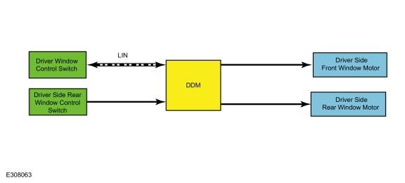
Driver Side Power Windows
.jpg)
| Item | Description |
|---|---|
| 1 | LIN |
| 2 | Driver Side Front Window Motor |
| 3 | Driver Side Rear Window Control Switch |
| 4 | Driver Window Control Switch |
| 5 | DDM |
| 6 | Driver Side Rear Window Motor |
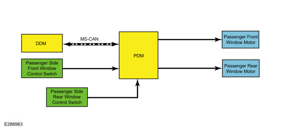
Passenger Side Power Windows
.jpg)
| Item | Description |
|---|---|
| 1 | Passenger Front Window Motor |
| 2 | Passenger Rear Window Motor |
| 3 | Passenger Side Rear Window Control Switch |
| 4 | Passenger Side Front Window Control Switch |
| 5 | PDM |
| 6 | DDM |
| 7 | MS-CAN |
Network Message Chart - Power Windows
Passenger Door Module (PDM) Network Input Messages
| Broadcast Message | Originating Module | Message Purpose |
|---|---|---|
| Passenger window command | DDM | When activating the passenger front or rear windows from the driver window control switch, the passenger window command is sent from the DDM to the PDM . |
| Rear window disable command | DDM | When the lock out switch (located in the driver window control switch) is in the LOCK position, the DDM sends this command to the PDM to disable rear passenger window operation from the rear passenger window control switches. |
System Diagram - Rear Window Defrost
.jpg)
.jpg)
| Item | Description |
|---|---|
| 1 | BJB |
| 2 | HVAC Module |
| 3 | MS-CAN |
| 4 | Rear Window Defrost Grid |
| 5 | GWM |
| 6 | BCM |
| 7 | HS-CAN1 |
| 8 | LIN |
Network Message Chart - Rear Window Defrost
BCMC Network Input Messages
| Broadcast Message | Originating Module | Message Purpose |
|---|---|---|
| Rear window defrost request | HVAC module | When the BCM receives the rear window defrost request message, a request is sent through a LIN to the BJB to activate the rear window defrost system. |
Power Window Operation
Voltage is supplied to the power window system whenever the ignition is on, or whenever the ignition is changed from on to off while the LH and RH front doors are closed. The voltage supplied to the power window system is removed when:
- the LH or RH front door is ajar and the ignition is off.
- ten minutes have elapsed since the ignition status has changed from on to the off position.
Front Power Window Operation
NOTE: If the battery is disconnected while the window is moving, the one-touch up and one-touch down feature (and obstacle detection) is disabled prior to initialization.
Refer to: Power Door Window Initialization - Vehicles With:
One-Touch Open and Close Front Windows (501-11 Glass, Frames and
Mechanisms, General Procedures).
Both front windows are equipped with obstacle detection and one-touch up and one-touch down functionality. If an obstacle has been detected in the window opening as the window glass is moving upward, the window regulator motor automatically reverses direction and moves the window glass downward.
Driver Side Front Window Operation
The driver window control switch communicates to the DDM through a private LIN . When commanded by the driver window control switch, the DDM supplies power and ground to operate the driver front window in the desired direction. The DDM monitors fluctuations of the motor current (ripple count for DC motors) to determine the window glass position.
Passenger Side Front Window Operation
The driver window control switch communicates to the DDM through a private LIN . The DDM communicates to the PDM through the MS-CAN . When commanded by the driver window control switch or the passenger front window control switch, the PDM supplies power and ground to operate the passenger side front window in the desired direction. The PDM monitors fluctuations of the motor current (ripple count for DC motors) to determine the window glass position.
Rear Power Window Operation
NOTE: If the battery is disconnected while the window is moving, the one-touch up and one-touch down feature (and obstacle detection) is disabled prior to initialization.
Refer to: Power Door Window Initialization - Vehicles With:
One-Touch Open and Close Front Windows (501-11 Glass, Frames and
Mechanisms, General Procedures).
Both rear windows are equipped with obstacle detection and one-touch up and one-touch down functionality. If an obstacle has been detected in the window opening as the window glass is moving upward, the window motor automatically reverses direction and moves the glass downward.
Driver Side Rear Window Operation
The driver window control switch communicates to the DDM through a private LIN . The rear door window control switch is wired directly to the DDM . When commanded by the driver window control switch or the rear window control switch, the DDM supplies power and ground to operate the driver side rear window in the desired direction. The DDM monitors fluctuations of the motor current (ripple count for DC motors) to determine the window glass position.
Passenger Side Rear Window Operation
The driver window control switch communicates to the DDM through a private LIN . The DDM communicates to the PDM through the MS-CAN . The rear door window control switch is wired directly to the PDM . When commanded by the driver window control switch or the rear window control switch, the PDM supplies power and ground to operate the passenger side rear window in the desired direction. The PDM monitors fluctuations of the motor current (ripple count for DC motors) to determine the window glass position.
Rear Passenger Windows Lock Out
When the lock out switch (part of the driver window control switch) is in the LOCK position, the rear passenger power windows only operate from the driver window control switch.
Rear Window Defrost
The rear window defrost system only operates when the engine is running. When the rear window defrost switch is activated, the HVAC module sends the request message to the BCM and then through a LIN to the BJB . The BJB activates the rear window defrost relay (integral to the BJB ). When the rear window defrost relay is activated, the rear window defrost grid(s) are energized. In some cases, the rear window defrost system may automatically activate as an extra load for accelerated engine warm-up. However the rear window defrost status LED remains off unless the rear window defrost switch is activated.
The BJB deactivates the rear window defrost relay when any of these conditions is met:
- The rear window defrost switch is pressed when the feature is active.
- Ignition state is changed from on to off.
- A predetermined timer completes.
- Battery voltage has dropped below a specified threshold (load management strategy).
Component Description
Driver Window Control Switch
The driver window control switch receives voltage whenever the accessory delay relay is active. The driver window control switch communicates to the DDM through a private LIN .
Front Passenger Door Window Control Switch
The front passenger window control switch contains momentary contacts (one for each window switch direction). The PDM provides a return (ground) for the front passenger window control switch. When the control switch is activated, a ground signal is supplied to the PDM to operate the window motor in the desired direction.
Rear Door Window Control Switch
Each of the rear door window control switches contains momentary contacts (one for each window switch direction). The DDM or PDM provides a return (ground) for the rear window control switch. When the control switch is activated, a ground signal is supplied to the DDM or PDM to operate the window motor in the desired direction.
Window Regulator Motor
The window regulator motor(s) are bi-directional. Window direction is determined by the polarity of the voltage being supplied to the motor from the associated door module.
Driver Door Module (DDM)
The DDM receives power window commands from the driver window control switch and the driver side rear door window control switch. The DDM supplies voltage and ground to operate the driver side front and rear power window regulator motors.
The DDM also communicates driver window control switch requests to the PDM through the MS-CAN . PMI is required whenever installing a new module.
Passenger Door Module (PDM)
The PDM receives power window commands from the passenger front door window control switch or from the DDM through the MS-CAN . The PDM supplies voltage and ground to operate the passenger front and rear power window regulator motors. PMI is required whenever installing a new module.
BCM
When a rear window defrost request message is sent to the BCM , the BCM sends a request to the BJB through a LIN to activate the rear window defrost system. PMI is required whenever installing a new module.
HVAC Module
The HVAC module contains the rear window defrost switch. PMI is required whenever installing a new module.
 Description and Operation - Glass, Frames and Mechanisms - Vehicles With: One-Touch Open Driver Window - Overview
Overview
Power Window Operation
The
power windows operate only when the ignition is on, or up to 10 minutes
after the ignition is changed from on to off while the front driver and
passenger doors remain closed...
 Description and Operation - Glass, Frames and Mechanisms - Vehicles
With: One-Touch Open Driver Window - System Operation and Component
Description
Description and Operation - Glass, Frames and Mechanisms - Vehicles
With: One-Touch Open Driver Window - System Operation and Component
Description
System Operation
System Diagram - Rear Window Defrost
Item
Description
1
BJB
2
HVAC Module
3
MS-CAN
4
Rear Window Defrost Grid
5
GWM
6
BCM
7
HS-CAN1
8
LIN
Network Message Chart - Rear Window Defrost
BCMC Network Input Messages
Broadcast Messa..
Other information:
Ford Escape 2020-2025 Service Manual: Description and Operation - Blind Spot Information System - Overview
BLIS ® The BLIS ® aids the driver in assessing whether another vehicle is present within a specific area (blind spot) to either side of the vehicle, extending rearward approximately 6 m (20 ft) beyond the rear bumper while driving on roads and highways. The system is not designed to prevent contact with other vehicles or objects. The BLIS ® uses the exterior mirror BLIS ® Light Emitti..
Ford Escape 2020-2025 Service Manual: Removal and Installation - Front Door Latch
Removal NOTE: LH (left-hand) side shown, RH (right-hand) side similar. NOTE: Removal steps in this procedure may contain installation details. Remove the front door window regulator and motor. Refer to: Front Door Window Regulator and Motor (501-11 Glass, Frames and Mechanisms, Removal and Installation). Remove the exterior front door handle. Refer to: Exterior F..
Categories
- Manuals Home
- 4th Generation Ford Escape Owners Manual
- 4th Generation Ford Escape Service Manual
- All-Wheel Drive
- General Procedures - Transmission Fluid Level Check
- Switching the Lane Keeping System On and Off. Switching the Lane Keeping System Mode. Alert Mode
- New on site
- Most important about car
Symbols Glossary
These are some of the symbols you may see on your vehicle.
 Air conditioning system