Ford Escape: Steering Wheel and Column Electrical Components / Description and Operation - Steering Wheel and Column Electrical Components - System Operation and Component Description
System Operation
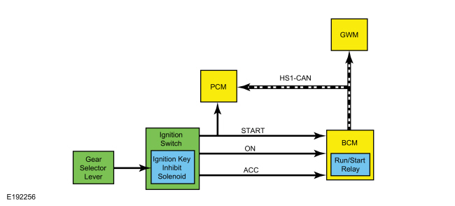
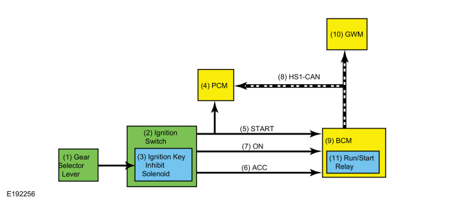
System Diagram - Conventional Ignition Switch
| Item | Description |
|---|---|
| 1 | Gear Selector Lever |
| 2 | Ignition Switch |
| 3 | Ignition Key Inhibit Solenoid |
| 4 | PCM |
| 5 | START |
| 6 | ACC |
| 7 | ON |
| 8 | HS-CAN1 |
| 9 | BCM |
| 10 | GWM |
| 11 | Run/Start Relay |
Network Message Chart - Conventional Ignition Switch
GWM Module Network Input Messages
| Broadcast Message | Originating Module | Message Purpose |
|---|---|---|
| Ignition status | BCM | Informs the GWM of the current ignition status; off, on, start, unknown or invalid. |
PCM Module Network Input Messages
| Broadcast Message | Originating Module | Message Purpose |
|---|---|---|
| Ignition status | BCM | Informs the PCM of the current ignition status; off, on, start, unknown or invalid. |
Ignition Switch System
The BCM controls the ignition modes, including OFF, ACC, ON and START. This allows some systems to be activated without starting the vehicle.
The BCM provides voltage at all times to the ignition switch. Depending on the ignition switch position, voltage may be routed to one or two of the ignition switch input circuits back to the BCM .
OFF
When the ignition switch is in the OFF position, the switch is open, preventing any voltage signals from reaching the BCM . When the BCM does not detect voltage from any of the ignition mode-designated circuits, the BCM interprets this as the ignition off mode.
The BCM communicates the ignition mode to the other modules by sending an ignition status message over the CAN and does not energize any relays to prevent voltage from being distributed to the various electrical systems.
ACC
When the ignition switch is in the ACC position, the switch routes voltage through the ACC-designated circuit to the BCM . The BCM interprets this as the ignition accessory mode.
The BCM communicates the ignition mode to the other modules by sending an ignition status message over the CAN and energizes the accessory designated relays and provides power to some electrical systems.
ON
When the ignition switch is in the ON position, the switch routes voltage through the ACC-designated and ON-designated circuits to the BCM . The BCM interprets this as the ignition on mode.
The BCM communicates the ignition mode to the other modules by sending an ignition status message over the CAN and activates the internal run/start relay, providing ignition power to the various vehicle systems and modules.
START
When the ignition switch is placed in the START position, the switch routes voltage through the ON-designated and START-designated circuits to the BCM .
The BCM interprets this as the ignition start mode and communicates the ignition mode to the other modules by sending an ignition status message over the CAN . Additionally, the ignition switch routes voltage to the PCM indicating a request to start the vehicle.
The START-designated circuit is only used for vehicle starting.
Ignition Key Inhibit
The ignition key inhibit feature prevents the ignition lock cylinder from being rotated to the OFF/LOCK position when the vehicle is not in PARK.
The key removal inhibit solenoid receives battery voltage at all times. The ground control circuit for the key removal inhibit solenoid is routed to a park detect switch within the selector lever assembly. The ground is controlled by the BCM .
When the selector lever is in PARK, the park detect switch inside the selector lever assembly is open, preventing the solenoid from actuating. When the selector lever is moved out of PARK, the switch closes and completes the circuit to the BCM .
The BCM controls the ground by means of a Field Effect Transistor (FET). The BCM enables the path to ground when it detects the vehicle is not in PARK based on messages received over the CAN .
When the selector lever is in PARK, the key removal inhibit solenoid deactivates and allows the ignition lock cylinder to be turned to the OFF/LOCK position to remove the key.
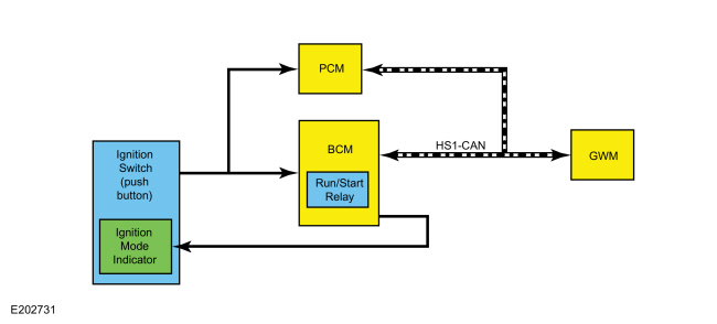
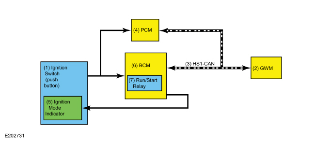
System Diagram - Push Button Ignition Switch
| Item | Description |
|---|---|
| 1 | Ignition Switch (push button) |
| 2 | GWM |
| 3 | HS-CAN1 |
| 4 | PCM |
| 5 | Ignition Mode Indicator |
| 6 | BCM |
| 7 | Run/Start Relay |
Network Message Chart - Push Button Ignition Switch
GWM Module Network Input Messages
| Broadcast Message | Originating Module | Message Purpose |
|---|---|---|
| Ignition status | BCM | Informs the GWM of the current ignition status; off, run, start, unknown or invalid. |
PCM Module Network Input Messages
| Broadcast Message | Originating Module | Message Purpose |
|---|---|---|
| Ignition status | BCM | Informs the PCM of the current ignition status; off, run, start, unknown or invalid. |
Push Button Ignition Switch
The push button ignition switch controls the ignition mode.
There are 2 circuits the BCM
monitors from the push button ignition switch to change the ignition
mode. One circuit is monitored for voltage and the other for a ground
signal. When the START/STOP button is pressed, one circuit routes
battery voltage to the BCM while a voltage signal from the BCM
on the second circuit is routed to ground, indicating a request to
change the ignition mode. Changing the ignition mode out of OFF works in
conjunction with the PATS . The BCM must recognize a valid programmed key before it changes the ignition mode out of OFF.
Refer
to: Steering Wheel and Column Electrical Components - System Operation
and Component Description (211-05 Steering Wheel and Column Electrical
Components, Description and Operation).
Refer to the following table for information about achieving the various ignition modes.
| Ignition Entry Condition | Desired Ignition Mode | Action To Take |
|---|---|---|
| Off | ON (engine off) | Press the START/STOP button without applying the brake pedal. |
| Off or on | START | Apply the brake pedal and then press the START/STOP button. |
| On (engine off) | OFF | Press the START/STOP button. |
| On (engine running) | OFF | Press and hold the START/STOP button. |
Ignition Mode LED Indicator
The ignition mode LED indicates the ignition mode of the vehicle. The BCM controls the voltage to the ignition mode LED indicator. Refer to the following table.
| Ignition Mode | Ignition Mode LED Indicator |
|---|---|
| Off | Off |
| On (engine off) | Flashing |
| On (engine running) | On |
OFF
The BCM controls the relays providing voltage to the vehicle electrical systems. When the ignition is in the ON mode, a single press and release of the START/STOP button (without applying the brake pedal) changes the ignition to the OFF mode. No programmed key is required to change the ignition to the OFF mode when the vehicle is running.
If the vehicle is in motion, a momentary press of the START/STOP button does not shut the vehicle off. If the vehicle is moving at a speed greater than 15 km/h (9 mph), the START/STOP button must be pressed and held for longer than one second (or pressed 3 times within 2 seconds) to turn the ignition off.
When the BCM changes the ignition mode to OFF, it communicates the ignition mode to the other modules by sending an ignition status message over the CAN .
ON
When the ignition is in the ON mode, the BCM activates the run/start relay to provide voltage to the vehicle electrical systems and communicates the ignition mode to the other modules by sending an ignition status message over the CAN .
When the vehicle enters ON mode, multiple indicators in the IPC prove out and the IPC displays the gear selection and the vehicle mileage.
START
If the brake pedal is applied when the START/STOP button is pressed, and a valid key is detected within the vehicle, the vehicle temporarily goes into the START mode.
In addition to activating the run/start relay, the BCM communicates the ignition mode to the other modules by sending an ignition status message over the CAN .
After the ignition has completed the vehicle start sequence, the ignition mode returns to ON and the ignition mode indicator in the ignition switch illuminates steadily.
The engine can be started from any ignition mode.
System Diagram - Heated Steering Wheel
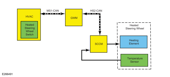
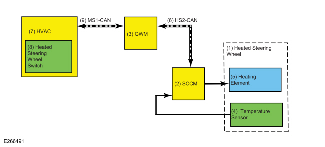
| Item | Description |
|---|---|
| 1 | Heated Steering Wheel |
| 2 | SCCM |
| 3 | GWM |
| 4 | Temperature Sensor |
| 5 | Heating Element |
| 6 | HS-CAN2 |
| 7 | HVAC |
| 8 | Heated Steering Wheel Switch |
| 9 | MS-CAN |
Network Message Chart - Heated Steering Wheel
SCCM Network Input Messages
| Broadcast Message | Originating Module | Message Purpose |
|---|---|---|
| Engine power status | PCM | Indicates to the SCCM whether the engine is running. |
| Ignition status | BCM | Indicates which ignition mode is active. |
| Steering wheel heat request | FCIM | To activate the heated steering wheel function when the touchscreen button is pressed on the FDIM , or when the conditions are met to activate the heated steering wheel (and heated seats) during a remote start. |
FCIM Module Network Input Messages
| Broadcast Message | Originating Module | Message Purpose |
|---|---|---|
| Heated steering wheel command status | APIM | Informs the FCIM that the heated steering wheel touchscreen button was pressed on the FDIM . |
| Ambient exterior temperature data | IPC | Used by the FCIM when determining if outside conditions are cold enough to request the heated steering wheel be activated during remote start operation. |
Heated Steering Wheel
When the engine is running and the SCCM receives a request to heat the steering wheel, the SCCM applies voltage and ground to the steering wheel heating elements (integral to the steering wheel) to heat the steering wheel to a temperature of approximately 82-94°F (28-34°C). The heated steering wheel temperature is maintained by the SCCM using a temperature sensor in the steering wheel.
The SCCM is designed to remain on, heating the steering wheel and maintaining the temperature until switched off on the FDIM or the ignition is turned off.
The controls and indicators for the heated steering wheel system are located on the FDIM (touchscreen) only. The FDIM does not communicate on any network and is connected directly to the APIM .
Remote Start System
The heated steering wheel system (along with the heated front seats) may be configured using the message center to activate (based on outside temperature) when the remote start feature is used. During remote start, the outside air temperature is continually monitored by the HVAC system. The heated steering wheel system activation changes if the outside air changes from cold to moderate or warm temperatures or back from moderate or warm to cold temperatures.
Component Description
Conventional Ignition Switch
The ignition switch is a multiple position rotary switch that is controlled by a lock cylinder and a key. The ignition switch is monitored by the BCM , which controls the voltage to the various electrical systems depending on input from the ignition switch.
The key removal inhibit solenoid (internal to the ignition switch) is an electronically controlled solenoid that prevents the ignition lock cylinder from being turned to the OFF/LOCK position unless the selector lever is in the PARK position. This also prevents the key from being removed from the ignition lock cylinder.
Push Button Ignition Switch
The push button ignition switch is a momentary dual contact switch that provides direct input to the BCM and PCM . Both sets of contacts are normally open. When the START/STOP button is pressed, one set of contacts provides a ground signal to the BCM and the other set of contacts supplies voltage to the BCM and the PCM .
The ignition mode LED indicator is located near the top of the START/STOP button and is controlled by the BCM .
Steering Column Control Module
The SCCM controls the steering wheel heating elements. The SCCM uses the steering wheel temperature sensor to maintain the steering wheel temperature. The SCCM is designed to remain on, heating the steering wheel and maintaining temperature until switched off using the FDIM or the ignition is turned off.
The SCCM requires PMI when replaced.
Body Control Module
The BCM controls the run/start relays and sets the vehicle ignition mode based on inputs from the ignition switch. It communicates the ignition mode to other modules over the CAN . If a fault is detected with the ignition switch system, Diagnostic Trouble Codes (DTCs) are set in the BCM .
The BCM requires at least 2 keys to be programmed and PMI when replaced. Additionally, the parameter reset procedure must be carried out.
 Description and Operation - Steering Wheel and Column Electrical Components - Overview
Steering Column Switches Overview
The
steering column switches are located on and around the steering column.
They enable the driver to control various vehicle functions while
remaining focused on driving...
 Diagnosis and Testing - Steering Wheel and Column Electrical Components
Diagnostic Trouble Code (DTC) Chart
Diagnostics in this manual assume a certain skill level and knowledge of Ford-specific diagnostic practices. REFER to: Diagnostic Methods (100-00 General Information, Description and Operation)...
Other information:
Ford Escape 2020-2025 Owners Manual: Wireless Accessory Charger
What Is the Wireless Accessory Charger The wireless accessory charger allows you to charge one compatible Qi wireless charging device on the charging area. Wireless Accessory Charger Precautions WARNING: Wireless charging devices can affect the operation of implanted medical devices, including cardiac pacemakers...
Ford Escape 2020-2025 Service Manual: Removal and Installation - Crankshaft Position (CKP) Sensor
Special Tool(s) / General Equipment 303-1699Tool, Crank Sensor Alignment 303-507Timing Peg, Crankshaft TDCTKIT-2001N-FLMTKIT-2001N-ROW Ford Diagnostic Equipment Removal NOTICE: During engine repair procedures, cleanliness is extremely important...
Categories
- Manuals Home
- 4th Generation Ford Escape Owners Manual
- 4th Generation Ford Escape Service Manual
- Electric Parking Brake
- Drive Modes
- What Is the Tire Pressure Monitoring System. Tire Pressure Monitoring System Overview
- New on site
- Most important about car
Engine Oil
Engine Oil Dipstick Overview
