Ford Escape Manuals
Ford Escape 2020-2024 Service Manual / Chassis / Steering System / Steering Wheel and Column Electrical Components / Diagnosis and Testing - Steering Wheel and Column Electrical Components

Ford Escape: Steering Wheel and Column Electrical Components / Diagnosis and Testing - Steering Wheel and Column Electrical Components

Diagnostic Trouble Code (DTC) Chart

Diagnostics in this manual assume a certain skill level and knowledge of Ford-specific diagnostic practices.
REFER to: Diagnostic Methods (100-00 General Information, Description and Operation).


  Diagnostic Trouble Code Chart


Module   DTC Description Action
  PCM P2534:00 Ignition Switch Run/Start Position Circuit Low: No Sub Type Information
  • For Conventional Ignition Switch: GO to Pinpoint Test D
  • For Push Button Ignition Switch: GO to Pinpoint Test H
  PCM P2535:00 Ignition Switch Run/Start Position Circuit Low: No Sub Type Information
  • For Conventional Ignition Switch: GO to Pinpoint Test D
  • For Push Button Ignition Switch: GO to Pinpoint Test H
  BCM B108A:01 Start Button: General Electrical Failure   GO to Pinpoint Test H
  BCM B108A:24 Start Button: Signal Stuck High   GO to Pinpoint Test H
  BCM B108A:9E Start Button: Stuck On   GO to Pinpoint Test H
  BCM B10F1:14 Key In Circuit:Circuit Short To Ground or Open   GO to Pinpoint Test G
  BCM B1142:29 Ignition Status 1: Signal Invalid   GO to Pinpoint Test C
  BCM B1142:29 Ignition Status 1: Signal Invalid   GO to Pinpoint Test H
  BCM B1240:11 Start Button Mode Indicator: Circuit Short to Ground   GO to Pinpoint Test I
  BCM B1240:15 Start Button Mode Indicator: Circuit Short to Battery or Open   GO to Pinpoint Test J
  BCM B1310:12 Run/Start Control: Circuit Short to Battery   GO to Pinpoint Test C
  BCM B1310:12 Run/Start Control: Circuit Short to Battery   GO to Pinpoint Test H
  BCM B1310:14 Run/Start Control: Circuit Short to Ground or Open   GO to Pinpoint Test C
  BCM B1310:14 Run/Start Control: Circuit Short to Ground or Open   GO to Pinpoint Test H
  BCM B1472:12 Ignition Key Removal Inhibit:Circuit Short To Battery   GO to Pinpoint Test F
  BCM B1472:14 Ignition Key Removal Inhibit:Circuit Short To Ground or Open   GO to Pinpoint Test F
  BCM U300A:01 Ignition Switch: General Electrical Failure   GO to Pinpoint Test B
  BCM U300A:01 Ignition Switch: General Electrical Failure   GO to Pinpoint Test L
  SCCM B112B:04 Steering Wheel Module: System Internal Failure   GO to Pinpoint Test P
  SCCM B112B:44 Steering Wheel Module: Data Memory Failure   GO to Pinpoint Test P
  SCCM B112B:45 Steering Wheel Module: Program Memory Failure   GO to Pinpoint Test P
  SCCM B112B:46 Steering Wheel Module: Calibration / Parameter Memory Failure   GO to Pinpoint Test P
  SCCM B112B:49 Steering Wheel Module: Internal Electronic Failure   GO to Pinpoint Test P
  SCCM B135C:11 Heater Element: Circuit Short To Ground   GO to Pinpoint Test O
  SCCM B135C:13 Heater Element: Circuit Open   GO to Pinpoint Test O
  SCCM U0140:00 Lost Communication With Body Control Module: No Sub Type Information   GO to Pinpoint Test Q
  SCCM U0146:00 Lost Communication With Gateway "A": No Sub Type Information   GO to Pinpoint Test Q
  SCCM U0155:00 Lost Communication With Instrument Panel Cluster Module: No Sub Type Information   GO to Pinpoint Test Q
  SCCM U023A:00 Lost Communication With Image Processing Module "A": No Sub Type Information   GO to Pinpoint Test Q
  SCCM U210A:11 Temperature Sensor: Circuit Short To Ground   GO to Pinpoint Test O
  SCCM U210A:13 Temperature Sensor: Circuit Open   GO to Pinpoint Test O
  SCCM U210A:29 Temperature Sensor: Signal Invalid   GO to Pinpoint Test O
  SCCM U2200:00 Control Module Configuration Memory Corrupt: No Sub Type Information   GO to Pinpoint Test P
  SCCM U3003:A2 Battery Voltage: System Voltage Low   GO to Pinpoint Test M
  SCCM U3003:A3 Battery Voltage: System Voltage High   GO to Pinpoint Test N

Global Customer Symptom Code (GCSC) Chart

Diagnostics in this manual assume a certain skill level and knowledge of Ford-specific diagnostic practices.
REFER to: Diagnostic Methods (100-00 General Information, Description and Operation).


Symptom Action
Start/Run/Move > Starting > Ignition Switch/Key > Sticks/Binds GO to Pinpoint Test E
Start/Run/Move > Starting > Push Button Start > Inoperative GO to Pinpoint Test I
Start/Run/Move > Starting > Push Button Start > Inoperative GO to Pinpoint Test K
Stop/Steer/Ride > Steering/Steering Wheel > Performance > Inoperative GO to Pinpoint Test O

Symptom Charts

Symptom Chart: Ignition Switch - Conventional

Diagnostics in this manual assume a certain skill level and knowledge of Ford-specific diagnostic practices.
REFER to: Diagnostic Methods (100-00 General Information, Description and Operation).


  Symptom Chart


Condition Actions
No power in all ignition switch positions
  • GO to Pinpoint Test A
No power in ACC
  • GO to Pinpoint Test B
No power in ON
  • GO to Pinpoint Test C
No power in START
  • GO to Pinpoint Test A
Key not detected displays in the message center

  • REFER to: Passive Anti-Theft System (PATS) (419-01C Passive Anti-Theft System (PATS) - Vehicles With: Keyless Vehicle System, Diagnosis and Testing).
The ignition key cannot be returned to the OFF position
  • GO to Pinpoint Test E
The ignition key can be turned to the OFF position when the selector lever is not in PARK
  • GO to Pinpoint Test F
The ignition lock cylinder is difficult to turn
  • GO to Pinpoint Test E

Symptom Chart: Ignition Switch - Push Button

Diagnostics in this manual assume a certain skill level and knowledge of Ford-specific diagnostic practices.
REFER to: Diagnostic Methods (100-00 General Information, Description and Operation).


  Symptom Chart


Condition Actions
No power in ON
  • GO to Pinpoint Test H
Key not detected displays in the message center

  • REFER to: Passive Anti-Theft System (PATS) (419-01C Passive Anti-Theft System (PATS) - Vehicles With: Keyless Vehicle System, Diagnosis and Testing).
The ignition mode indicator is inoperative
  • GO to Pinpoint Test I
The ignition mode indicator is always on
  • GO to Pinpoint Test J
Vehicle starts with no IA keyfob present
  • GO to Pinpoint Test K

Symptom Chart: Heated Steering Wheel

Diagnostics in this manual assume a certain skill level and knowledge of Ford-specific diagnostic practices.
REFER to: Diagnostic Methods (100-00 General Information, Description and Operation).


  Symptom Chart


Condition Actions
The heated steering wheel is inoperative or does not operate correctly
  • GO to Pinpoint Test O

Pinpoint Tests


PINPOINT TEST A: NO POWER IN ALL IGNITION SWITCH POSITIONS - CONVENTIONAL IGNITION SWITCH

Refer to Wiring Diagrams Cell 13 for schematic and connector information.

Normal Operation and Fault Conditions

REFER to: Steering Wheel and Column Electrical Components - System Operation and Component Description (211-05 Steering Wheel and Column Electrical Components, Description and Operation).

Possible Sources

  • Fuse
  • Wiring, terminals or connectors
  • Ignition switch
  • BCM

Visual Inspection and Pre-checks

  • Inspect the battery and battery cables.
  • Inspect the BCM fuse 4 (10A).

NOTICE: Use the correct probe adapter(s) when making measurements. Failure to use the correct probe adapter(s) may damage the connector.

A1 CHECK THE VEHICLE BATTERY
  • Carry out the Battery Condition Test.
    REFER to: Battery (414-01 Battery, Mounting and Cables, Diagnosis and Testing).

Is the battery OK?
Yes GO to A2
No CORRECT the battery condition.

A2 CHECK FOR VOLTAGE TO THE IGNITION SWITCH
  • Ignition OFF.
  • Disconnect Ignition Switch C250 .
  • Measure:
    Click to display connectors
    Positive Lead Measurement / Action Negative Lead
      C250-4   Ground

Is the voltage greater than 11 volts?
Yes INSTALL a new ignition switch.
REFER to: Ignition Switch (211-05 Steering Wheel and Column Electrical Components, Removal and Installation).
No VERIFY the BCM fuse 4 (10A) is OK. If OK, GO to A3
If not OK, REFER to the Wiring Diagrams manual to identify the possible causes of the circuit short.

A3 CHECK THE IGNITION SWITCH VOLTAGE SUPPLY CIRCUIT FOR AN OPEN
  • Disconnect BCM C2280D .
  • Measure:
    Click to display connectors
    Positive Lead Measurement / Action Negative Lead
      C250-4   C2280D-24

Is the resistance less than 3 ohms?
Yes GO to A4
No REPAIR the circuit.

A4 CHECK FOR CORRECT BCM (BODY CONTROL MODULE) OPERATION
  • Disconnect and inspect all BCM connectors.
  • Repair:
    • corrosion (install new connector or terminals - clean module pins)
    • damaged or bent pins - install new terminals/pins
    • pushed-out pins - install new pins as necessary
  • Reconnect the BCM connectors and all other previously disconnected connectors. Make sure they seat and latch correctly.
  • Operate the system and determine if the concern is still present.

Is the concern still present?
Yes INSTALL a new BCM. Refer to the appropriate Removal and Installation procedure in Section 419-10.
No The system is operating correctly at this time. The concern may have been caused by module connections. ADDRESS the root cause of any connector or pin issues.

PINPOINT TEST B: NO POWER IN ACC - CONVENTIONAL IGNITION SWITCH

Refer to Wiring Diagrams Cell 13 for schematic and connector information.

Normal Operation and Fault Conditions

REFER to: Steering Wheel and Column Electrical Components - System Operation and Component Description (211-05 Steering Wheel and Column Electrical Components, Description and Operation).

DTC Fault Trigger Conditions

DTC Description Fault Trigger Condition
BCM U300A:01 Ignition Switch: General Electrical Failure This DTC sets if the BCM detects an invalid combination from the conventional ignition switch input circuits.

Possible Sources

  • Wiring, terminals or connectors
  • Ignition switch
  • BCM

NOTICE: Use the correct probe adapter(s) when making measurements. Failure to use the correct probe adapter(s) may damage the connector.

B1 CHECK FOR BCM (BODY CONTROL MODULE) DTC (DIAGNOSTIC TROUBLE CODE) U300A:01
  • Ignition ON.
  • Using a diagnostic scan tool, carry out the BCM self-test.

Is DTC U300A:01 present?
Yes GO to Pinpoint Test L
No GO to B2

B2 CHECK FOR VOLTAGE TO THE BCM (BODY CONTROL MODULE) WITH THE IGNITION SWITCH IN THE ACC POSITION
  • Ignition OFF.
  • Disconnect BCM C2280D .
  • Accessory ON.
  • Measure:
    Click to display connectors
    Positive Lead Measurement / Action Negative Lead
      C2280D-35   Ground

Is the voltage greater than 11 volts?
Yes GO to B4
No GO to B3

B3 CHECK THE IGNITION ACC CIRCUIT FOR AN OPEN
  • Ignition OFF.
  • Disconnect Ignition Switch C250 .
  • Measure:
    Click to display connectors
    Positive Lead Measurement / Action Negative Lead
      C2280D-35   C250-6

Is the resistance less than 3 ohms?
Yes INSTALL a new ignition switch.
REFER to: Ignition Switch (211-05 Steering Wheel and Column Electrical Components, Removal and Installation).
No REPAIR the circuit.

B4 CHECK FOR VOLTAGE TO THE BCM (BODY CONTROL MODULE) WITH THE IGNITION SWITCH IN THE ON POSITION
  • Ignition ON.
  • Measure:
    Click to display connectors
    Positive Lead Measurement / Action Negative Lead
      C2280D-35   Ground

Is the voltage greater than 11 volts?
Yes GO to B5
No INSTALL a new ignition switch.
REFER to: Ignition Switch (211-05 Steering Wheel and Column Electrical Components, Removal and Installation).

B5 CHECK FOR CORRECT BCM (BODY CONTROL MODULE) OPERATION
  • Ignition OFF.
  • Disconnect and inspect all BCM connectors.
  • Repair:
    • corrosion (install new connector or terminals - clean module pins)
    • damaged or bent pins - install new terminals/pins
    • pushed-out pins - install new pins as necessary
  • Reconnect the BCM connectors. Make sure they seat and latch correctly.
  • Operate the system and determine if the concern is still present.

Is the concern still present?
Yes INSTALL a new BCM. Refer to the appropriate Removal and Installation procedure in Section 419-10.
No The system is operating correctly at this time. The concern may have been caused by module connections. ADDRESS the root cause of any connector or pin issues.

PINPOINT TEST C: NO POWER IN ON - CONVENTIONAL IGNITION SWITCH

Refer to Wiring Diagrams Cell 13 for schematic and connector information.

Normal Operation and Fault Conditions

REFER to: Steering Wheel and Column Electrical Components - System Operation and Component Description (211-05 Steering Wheel and Column Electrical Components, Description and Operation).

DTC Fault Trigger Conditions

DTC Description Fault Trigger Condition
BCM B1310:12 Run/Start Control: Circuit Short To Battery Sets when the BCM detects a short to voltage from the BJB run/start relay control circuit. When set, the control side of the run/start relay is disabled via the Field Effect Transistor (FET). Once the condition that caused the DTC to set is repaired, the BCM must pass a self-test in order for the DTC to clear and the system to resume normal operation.
BCM B1310:14 Run/Start Control: Circuit Short To Ground Or Open The BCM continuously monitors the control side of the RUN/START relay in the BJB . This DTC is set if the BCM detects an open or a short to ground on the control side of the RUN/START relay. When this DTC sets, the BCM disables the control side of the RUN/START relay FET. Once the condition that caused the DTC to set is repaired, the BCM must pass a self-test in order for the DTC to clear and the system to resume normal operation.
BCM B1142:29 Ignition Status 1: Signal Invalid Sets when the BCM does not receive a valid ignition signal during a BCM self-test.

Possible Sources

  • Network concern
  • Wiring, terminals or connectors
  • Ignition switch
  • BCM

Visual Inspection and Pre-checks

  • Inspect the BCM fuse 4 (10A) .

NOTICE: Use the correct probe adapter(s) when making measurements. Failure to use the correct probe adapter(s) may damage the connector.

C1 CHECK FOR BCM (BODY CONTROL MODULE) DTC (DIAGNOSTIC TROUBLE CODE) U300A:01
  • Using a diagnostic scan tool, carry out the BCM self-test.

Is DTC U300A:01 present?
Yes GO to Pinpoint Test L
No GO to C2

C2 CHECK FOR BCM (BODY CONTROL MODULE) DTC (DIAGNOSTIC TROUBLE CODE) B1310:12 OR B1310:14
  • Using a diagnostic scan tool, carry out the BCM self-test.

Is DTC B1310:12 or B1310:14 present?
Yes GO to C6
No GO to C3

C3 CHECK FOR VOLTAGE TO THE BCM (BODY CONTROL MODULE) WITH THE IGNITION SWITCH IN THE ON POSITION
  • Ignition OFF.
  • Disconnect BCM C2280D .
  • Ignition ON.
  • Measure:
    Click to display connectors
    Positive Lead Measurement / Action Negative Lead
      C2280D-34   Ground

Is the voltage greater than 11 volts?
Yes GO to C6
No GO to C4

C4 CHECK THE IGNITION ON-DESIGNATED INPUT CIRCUIT FOR A SHORT TO GROUND
  • Ignition OFF.
  • Disconnect Ignition Switch C250 .
  • Measure:
    Click to display connectors
    Positive Lead Measurement / Action Negative Lead
      C2280D-34   Ground

Is the resistance less than 3 ohms?
Yes REPAIR the circuit.
No GO to C5

C5 CHECK THE IGNITION ON-DESIGNATED INPUT CIRCUIT FOR AN OPEN
  • Ignition OFF.
  • Measure:
    Click to display connectors
    Positive Lead Measurement / Action Negative Lead
      C2280D-34   C250-2

Is the resistance less than 3 ohms?
Yes INSTALL a new ignition switch.
REFER to: Ignition Switch (211-05 Steering Wheel and Column Electrical Components, Removal and Installation).
No REPAIR the circuit.

C6 CHECK THE BJB (BATTERY JUNCTION BOX) RUN/START RELAY CONTROL CIRCUIT FOR A FOR A SHORT TO GROUND
  • Ignition OFF.
  • Disconnect BCM C2280E .
  • Disconnect BJB C1035A .
  • Measure:
    Click to display connectors
    Positive Lead Measurement / Action Negative Lead
      C2280E-36   Ground

Is the resistance less than 3 ohms?
Yes REPAIR the circuit.
No GO to C7

C7 CHECK THE BJB (BATTERY JUNCTION BOX) RUN/START RELAY CONTROL CIRCUIT FOR A FOR A SHORT TO VOLTAGE
  • Ignition OFF.
  • Measure:
    Click to display connectors
    Positive Lead Measurement / Action Negative Lead
      C2280E-36   Ground

Is any voltage present?
Yes REPAIR the circuit.
No GO to C8

C8 CHECK THE BJB (BATTERY JUNCTION BOX) RUN/START RELAY CONTROL CIRCUIT FOR A FOR AN OPEN
  • Ignition OFF.
  • Measure:
    Click to display connectors
    Positive Lead Measurement / Action Negative Lead
      C2280E-36   C1035A-33

Is the resistance less than 3 ohms?
Yes GO to C9
No REPAIR the circuit.

C9 CARRY OUT A NETWORK TEST
  • Connect BCM C2280E .
  • Connect BJB C1035A .
  • Using a diagnostic scan tool, perform the network test.

Do the IPC and the BCM pass the network test?
Yes GO to C10
No DIAGNOSE the network concern.
REFER to: Communications Network (418-00 Module Communications Network, Diagnosis and Testing).

C10 CHECK VOLTAGE SUPPLY TO THE BCM (BODY CONTROL MODULE)
  • Ignition OFF.
  • Disconnect BCM C2280A .
  • Ignition ON.
  • Measure:
    Positive Lead Measurement / Action Negative Lead
      C2280A-1   Ground

Is the voltage greater than 11 volts?
Yes GO to C12
No GO to C11

C11 CHECK THE BCM (BODY CONTROL MODULE) VOLTAGE SUPPLY CIRCUIT FOR AN OPEN
  • Disconnect BCM C2280A .
  • Measure:
    Positive Lead Measurement / Action Negative Lead
      C2280A-1   C1617C-1

Is the resistance LESS than 3 ohms?
Yes CHECK OASIS for any applicable service articles: TSB , GSB , SSM or FSA . If a service article exists for this concern, DISCONTINUE this test and FOLLOW the service article instructions. If no service articles address this concern, REPLACE the BCM.
REFER to: Body Control Module (BCM) (419-10 Multifunction Electronic Modules, Removal and Installation).
TEST the system for normal operation. If the concern is still present, GO to C12
No REPAIR the circuit.

C12 CHECK FOR CORRECT BCM (BODY CONTROL MODULE) OPERATION
  • Disconnect and inspect all BCM connectors.
  • Repair:
    • corrosion (install new connector or terminals - clean module pins)
    • damaged or bent pins - install new terminals/pins
    • pushed-out pins - install new pins as necessary
  • Reconnect the BCM connectors and all other previously disconnected connectors. Make sure they seat and latch correctly.
  • Operate the system and determine if the concern is still present.

Is the concern still present?
Yes CHECK OASIS for any applicable service articles: TSB , GSB , SSM or FSA . If a service article exists for this concern, DISCONTINUE this test and FOLLOW the service article instructions. If no service articles address this concern, INSTALL a new BCM. Refer to the appropriate Removal and Installation procedure in Section 419-10.
No The system is operating correctly at this time. The concern may have been caused by module connections. ADDRESS the root cause of any connector or pin issues.

PINPOINT TEST D: NO POWER IN START - CONVENTIONAL IGNITION SWITCH

Refer to Wiring Diagrams Cell 13 for schematic and connector information.

Normal Operation and Fault Conditions

REFER to: Steering Wheel and Column Electrical Components - System Operation and Component Description (211-05 Steering Wheel and Column Electrical Components, Description and Operation).

DTC Fault Trigger Conditions

DTC Description Fault Trigger Condition
PCM P2534:00 Ignition Switch On/Start Position Circuit Low: No Sub Type Information This DTC sets if the PCM detects a low voltage signal from the ignition switch input circuits.
PCM P2535:00 Ignition Switch On/Start Position Circuit High: No Sub Type Information This DTC sets if the PCM detects a high voltage signal from the ignition switch input circuits.

Possible Sources

  • Wiring, terminals or connectors
  • Ignition switch
  • PCM

NOTICE: Use the correct probe adapter(s) when making measurements. Failure to use the correct probe adapter(s) may damage the connector.

D1 CHECK FOR PCM (POWERTRAIN CONTROL MODULE) DTC (DIAGNOSTIC TROUBLE CODE) P2534 OR P2535
  • Ignition ON.
  • Using a diagnostic scan tool, carry out the PCM self-test.

Is DTC P2534 or P2535 present?
Yes For DTC P2534, GO to D2
For DTC P2535, GO to D5
No The system is operating correctly at this time. The concern may have been caused by module connections. ADDRESS the root cause of any connector or pin issues.

D2 CHECK FOR VOLTAGE TO THE PCM (POWERTRAIN CONTROL MODULE) WITH THE IGNITION SWITCH IN THE START POSITION
  • Ignition OFF.
  • Disconnect PCM C175B 1.5L .
  • Place the ignition switch in the START position.
  • Measure:
    Positive Lead Measurement / Action Negative Lead
      C175B-45   Ground

Is the voltage greater than 11 volts?
Yes GO to D5
No GO to D3

D3 CHECK THE IGNITION START CIRCUIT FOR AN OPEN
  • Ignition OFF.
  • Disconnect Ignition Switch C250 .
  • Measure:
    Positive Lead Measurement / Action Negative Lead
      C175B-45   C250-1

Is the resistance less than 3 ohms?
Yes GO to D4
No REPAIR the circuit.

D4 CHECK THE IGNITION START CIRCUIT FOR A SHORT TO GROUND
  • Ignition OFF.
  • Measure:
    Positive Lead Measurement / Action Negative Lead
      C175B-45   Ground

Is the resistance greater than 10,000 ohms?
Yes GO to D5
No REPAIR the circuit.

D5 CHECK THE IGNITION START CIRCUIT FOR A SHORT TO VOLTAGE
  • Ignition ON.
  • Measure:
    Positive Lead Measurement / Action Negative Lead
      C175B-45   Ground

Is any voltage present?
Yes REPAIR the circuit.
No GO to D6

D6 CHECK FOR CORRECT PCM (POWERTRAIN CONTROL MODULE) OPERATION
  • Ignition OFF.
  • Disconnect and inspect all PCM connectors.
  • Repair:
    • corrosion (install new connector or terminals - clean module pins)
    • damaged or bent pins - install new terminals/pins
    • pushed-out pins - install new pins as necessary
  • Reconnect the PCM , BCM and ignition switch connectors. Make sure they seat and latch correctly.
  • Operate the system and determine if the concern is still present.

Is the concern still present?
Yes CHECK OASIS for any applicable service articles: TSB , GSB , SSM , or FSA . If a service article exists for this concern, DISCONTINUE this test and FOLLOW the service article instructions. If no service articles address this concern,
   VIN required to access Guided Routine (PCM)
No The system is operating correctly at this time. The concern may have been caused by module connections. ADDRESS the root cause of any connector or pin issues.

PINPOINT TEST E: THE IGNITION KEY CANNOT BE RETURNED TO THE OFF POSITION

Refer to Wiring Diagrams Cell 37 for schematic and connector information.

Normal Operation and Fault Conditions

REFER to: Steering Wheel and Column Electrical Components - System Operation and Component Description (211-05 Steering Wheel and Column Electrical Components, Description and Operation).

Possible Sources

  • Wiring, terminals or connectors
  • Ignition switch
  • Ignition lock cylinder
  • Key Release Interlock Actuator
  • Selector lever assembly

NOTICE: Use the correct probe adapter(s) when making measurements. Failure to use the correct probe adapter(s) may damage the connector.

E1 CHECK FOR AN ENERGIZED KEY RELEASE INTERLOCK ACTUATOR
  • Disconnect BCM fuse 4 (10A).
  • Attempt to turn the ignition lock cylinder to the ON position and then back to the OFF-LOCK position and remove the key.

Can the ignition lock cylinder be turned to the OFF-LOCK position and the key removed?
Yes GO to E3
No GO to E2

E2 CHECK THE IGNITION SWITCH AND KEY RELEASE INTERLOCK ACTUATOR FOR MECHANICAL DAMAGE
  • Remove the ignition switch.
    REFER to: Ignition Switch (211-05 Steering Wheel and Column Electrical Components, Removal and Installation).
  • Attempt to turn the ignition lock cylinder to the OFF-LOCK position and remove the ignition key.

Does the ignition lock cylinder turn to the OFF-LOCK position and can the key be removed?
Yes INSTALL a new ignition switch.
REFER to: Ignition Switch (211-05 Steering Wheel and Column Electrical Components, Removal and Installation).
No INSTALL a new ignition lock cylinder.
REFER to: Ignition Lock Cylinder Housing (211-05 Steering Wheel and Column Electrical Components, Removal and Installation).

E3 CHECK THE KEY RELEASE INTERLOCK ACTUATOR CIRCUIT FOR A SHORT TO GROUND

NOTE: The following pinpoint test step uses a test lamp to simulate normal circuit loads. Use only a Rotunda Test Lamp (SGT27000) or 250- 300mA incandescent bulb test lamp. To avoid connector terminal damage, use the Rotunda Flex Probe kit for the test lamp probe connection to the vehicle. Do not use the test lamp probe directly on any connector.

  • Connect BCM fuse 4 (10A).
  • Select PARK.
  • Disconnect Key Release Interlock Actuator C2434 .
  • Connect:
    Click to display connectors
    Positive Lead Measurement / Action Negative Lead
      C2434-1   C2434-2

Does the test lamp illuminate?
Yes GO to E4
No INSTALL a new Key Release Interlock Actuator.
REFER to: Ignition Lock Cylinder Housing (211-05 Steering Wheel and Column Electrical Components, Removal and Installation).

E4 CHECK THE KEY RELEASE INTERLOCK ACTUATOR CONTROL CIRCUIT FOR A SHORT TO GROUND
  • Disconnect BCM C2280D .
  • Disconnect Key Release Interlock Actuator C2434 .
  • Connect:
    Click to display connectors
    Positive Lead Measurement / Action Negative Lead
      C2434-2   Ground

Is the resistance LESS than 3 ohms?
Yes REPAIR the circuit.
No GO to E5

E5 CHECK FOR CORRECT BCM (BODY CONTROL MODULE) OPERATION
  • Disconnect and inspect all BCM connectors.
  • Repair:
    • corrosion (install new connector or terminals - clean module pins)
    • damaged or bent pins - install new terminals/pins
    • pushed-out pins - install new pins as necessary
  • Reconnect the BCM connectors and all other previously disconnected connectors. Make sure they seat and latch correctly.
  • Operate the system and determine if the concern is still present.

Is the concern still present?
Yes CHECK OASIS for any applicable service articles: TSB , GSB , SSM or FSA . If a service article exists for this concern, DISCONTINUE this test and FOLLOW the service article instructions. If no service articles address this concern, INSTALL a new BCM. Refer to the appropriate Removal and Installation procedure in Section 419-10.
No The system is operating correctly at this time. The concern may have been caused by module connections. ADDRESS the root cause of any connector or pin issues.

PINPOINT TEST F: THE IGNITION KEY CAN BE TURNED TO THE OFF POSITION WHEN THE SELECTOR LEVER IS NOT IN PARK

Refer to Wiring Diagrams Cell 37 for schematic and connector information.

Normal Operation and Fault Conditions

REFER to: Steering Wheel and Column Electrical Components - System Operation and Component Description (211-05 Steering Wheel and Column Electrical Components, Description and Operation).

DTC Fault Trigger Conditions

DTC Description Fault Trigger Condition
BCM B1472:12 Ignition Key Removal Inhibit: Circuit Short To Battery Sets when the BCM detects a short to voltage from the key removal inhibit solenoid control circuit.
BCM B1472:14 Ignition Key Removal Inhibit: Circuit Short To Ground Or Open Sets when the BCM detects an open from the key removal inhibit solenoid control circuit.

Possible Sources

  • Wiring, terminals or connectors
  • Ignition switch
  • Selector lever assembly
  • BCM

NOTICE: Use the correct probe adapter(s) when making measurements. Failure to use the correct probe adapter(s) may damage the connector.

NOTE: The following Pinpoint Test uses a test lamp to simulate normal circuit loads. Use only a Rotunda Test Lamp (SGT27000) or 250- 300mA incandescent bulb test lamp. To avoid connector terminal damage, use the Rotunda Flex Probe kit for the test lamp probe connection to the vehicle. Do not use the test lamp probe directly on any connector.

F1 CHECK THE KEY RELEASE INTERLOCK ACTUATOR CIRCUIT FOR AN OPEN
  • Ignition OFF.
  • Disconnect Key Release Interlock Actuator C2434 .
  • Set the park brake.
  • Select NEUTRAL.
  • Connect:
    Click to display connectors
    Positive Lead Measurement / Action Negative Lead
      C2434-1   C2434-2

Is the test lamp illuminated?
Yes INSTALL a new Key Release Interlock Actuator.
REFER to: Ignition Lock Cylinder Housing (211-05 Steering Wheel and Column Electrical Components, Removal and Installation).
No GO to F2

F2 CHECK THE KEY RELEASE INTERLOCK ACTUATOR CONTROL CIRCUIT FOR AN OPEN
  • Disconnect BCM C2280D .
  • Disconnect Key Release Interlock Actuator C2434 .
  • Measure:
  • Measure:
    Click to display connectors
    Positive Lead Measurement / Action Negative Lead
      C2434-2   C2280D-17

Is the resistance less than 3 ohms on each circuit?
Yes GO to F3
No REPAIR the circuit.

F3 CHECK THE KEY RELEASE INTERLOCK ACTUATOR GROUND CIRCUIT FOR A SHORT TO VOLTAGE
  • Disconnect C2280D .
  • Disconnect C2434 .
  • Connect:
    Click to display connectors
    Positive Lead Measurement / Action Negative Lead
      C2434-2   Ground

Does the test lamp illuminate?
Yes REPAIR the circuit.
No GO to F4

F4 CHECK FOR CORRECT BCM (BODY CONTROL MODULE) OPERATION
  • Disconnect and inspect all BCM connectors.
  • Repair:
    • corrosion (install new connector or terminals - clean module pins)
    • damaged or bent pins - install new terminals/pins
    • pushed-out pins - install new pins as necessary
  • Reconnect the BCM connectors and all other previously disconnected connectors. Make sure they seat and latch correctly.
  • Operate the system and determine if the concern is still present.

Is the concern still present?
Yes CHECK OASIS for any applicable service articles: TSB , GSB , SSM or FSA . If a service article exists for this concern, DISCONTINUE this test and FOLLOW the service article instructions. If no service articles address this concern, INSTALL a new BCM. Refer to the appropriate Removal and Installation procedure in Section 419-10.
No The system is operating correctly at this time. The concern may have been caused by module connections. ADDRESS the root cause of any connector or pin issues.

PINPOINT TEST G: B10F1:14

Refer to Wiring Diagrams Cell 37 for schematic and connector information.

Normal Operation and Fault Conditions

REFER to: Steering Wheel and Column Electrical Components - System Operation and Component Description (211-05 Steering Wheel and Column Electrical Components, Description and Operation).

DTC Fault Trigger Conditions

DTC Description Fault Trigger Condition
BCM B10F1:14 Key In Switch: Circuit Short To Ground Or Open Sets when the BCM detects a short to ground or open circuit from the key in switch.

Possible Sources

  • Wiring, terminals or connectors
  • Ignition switch
  • BCM

NOTICE: Use the correct probe adapter(s) when making measurements. Failure to use the correct probe adapter(s) may damage the connector.

NOTE: The following Pinpoint Test uses a test lamp to simulate normal circuit loads. Use only a Rotunda Test Lamp (SGT27000) or 250- 300mA incandescent bulb test lamp. To avoid connector terminal damage, use the Rotunda Flex Probe kit for the test lamp probe connection to the vehicle. Do not use the test lamp probe directly on any connector.

G1 CHECK THE KEY IN CIRCUIT FOR SHORT TO GROUND
  • Ignition OFF.
  • Disconnect Ignition switch C250 .
  • Disconnect BCM C2280D .
  • Set the park brake.
  • Select NEUTRAL.
  • Connect:
    Click to display connectors
    Positive Lead Measurement / Action Negative Lead
      C2280D-22   Ground

Is the resistance less than 3 ohms?
Yes REPAIR the circuit
No GO to G2

G2 CHECK THE KEY IN CIRCUIT FOR AN OPEN
  • Measure:
    Click to display connectors
    Positive Lead Measurement / Action Negative Lead
      C2280D-22 C2280D-22   C250-3

Is the resistance less than 3 ohms ?
Yes GO to G3
No REPAIR the circuit.

G3 CHECK THE KEY IN CIRCUIT FOR A SHORT TO VOLTAGE
  • Disconnect C2280D .
  • Disconnect C250 .
  • Connect:
    Click to display connectors
    Positive Lead Measurement / Action Negative Lead
      C2280D-22 C2280D-22   Ground

Does the test lamp illuminate?
Yes REPAIR the circuit.
No GO to G4

G4 CHECK FOR CORRECT BCM (BODY CONTROL MODULE) OPERATION
  • Disconnect and inspect all BCM connectors.
  • Repair:
    • corrosion (install new connector or terminals - clean module pins)
    • damaged or bent pins - install new terminals/pins
    • pushed-out pins - install new pins as necessary
  • Reconnect the BCM connectors and all other previously disconnected connectors. Make sure they seat and latch correctly.
  • Operate the system and determine if the concern is still present.

Is the concern still present?
Yes CHECK OASIS for any applicable service articles: TSB , GSB , SSM or FSA . If a service article exists for this concern, DISCONTINUE this test and FOLLOW the service article instructions. If no service articles address this concern, INSTALL a new BCM .
REFER to: Body Control Module (BCM) (419-10 Multifunction Electronic Modules, Diagnosis and Testing).
No The system is operating correctly at this time. The concern may have been caused by module connections. ADDRESS the root cause of any connector or pin issues.

PINPOINT TEST H: NO POWER IN ON - PUSH BUTTON IGNITION SWITCH

Refer to Wiring Diagrams Cell 13 for schematic and connector information. Refer to Wiring Diagrams Cell 20 for schematic and connector information.

Normal Operation and Fault Conditions

REFER to: Steering Wheel and Column Electrical Components - System Operation and Component Description (211-05 Steering Wheel and Column Electrical Components, Description and Operation).

DTC Fault Trigger Conditions

DTC Description Fault Trigger Condition
PCM P2534:00 Ignition Switch On/Start Position Circuit Low: No Sub Type Information This DTC sets if the PCM detects a low voltage signal from the ignition switch input circuits.
PCM P2535:00 Ignition Switch On/Start Position Circuit High: No Sub Type Information This DTC sets if the PCM detects a high voltage signal from the ignition switch input circuits.
BCM B108A:01 Start Button: General Electrical Failure Sets continuous when the BCM detects a fault from one of the ignition switch input circuits.
BCM B108A:24 Start Button: Signal Stuck High Sets continuous when the BCM detects a fault from one of the ignition switch input circuits.
BCM B108A:9E Start Button: Stuck On Sets continuous when the BCM detects only one switch input circuit indicating open when the start button is released.
BCM B1142:29 Ignition Status 1: Signal Invalid Sets during the on-demand self-test when the BCM detects a fault from one of the ignition switch input circuits.
BCM B1310:12 Run/Start Control: Circuit Short To Battery Sets when the BCM detects a short to voltage on the BJB run/start relay control circuit. When set, the control side of the run/start relay is disabled via the Field Effect Transistor (FET) in the BCM . Once the condition that caused the DTC to set is repaired, the BCM must pass a self-test in order for the DTC to clear and the system to resume normal operation.
BCM B1310:14 Run/Start Control: Circuit Short To Ground Or Open The BCM continuously monitors the control side of the run/start relay in the BJB . This DTC is set if the BCM detects an open or a short to ground on the control side of the run/start relay. When this DTC sets, the BCM disables the control side of the RUN/START relay FET. Once the condition that caused the DTC to set is repaired, the BCM must pass a self-test in order for the DTC to clear and the system to resume normal operation.

Possible Sources

  • Battery voltage concern
  • Fuse
  • Wiring, terminals or connectors
  • PATS concern
  • Push button ignition switch
  • BCM

Visual Inspection and Pre-checks

  • Inspect the battery and battery cables.
  • Inspect the BCM fuse 4 (10A).

NOTICE: Use the correct probe adapter(s) when making measurements. Failure to use the correct probe adapter(s) may damage the connector.

H1 CHECK THE VEHICLE BATTERY
  • Carry out the Battery Condition Test.
    REFER to: Battery (414-01 Battery, Mounting and Cables, Diagnosis and Testing).

Is the battery OK?
Yes GO to H2
No CORRECT the battery condition.

H2 CHECK FOR BCM (BODY CONTROL MODULE) DTC (DIAGNOSTIC TROUBLE CODE) B1310:12 OR B1310:14
  • Using a diagnostic scan tool, carry out the BCM self-test.

Is DTC B1310:12 or B1310:14 present?
Yes GO to H17
No GO to H3

H3 CHECK FOR IGNITION ON MODE
  • NOTE: If DTC B108A:01, B108A:24, B108A:9E or B1142:29 is present, go to step H5. Press and release the START/STOP button while monitoring the ignition mode indicator at the top of the button.

Does the ignition mode indicator flash on and off continuously?
Yes GO to H17
No GO to H4

H4 CHECK FOR A PATS (PASSIVE ANTI-THEFT SYSTEM) CONCERN
  • Press the START/STOP button while monitoring the message center.

Does No key detected display in the message center?
Yes
REFER to: Passive Anti-Theft System (PATS) (419-01C Passive Anti-Theft System (PATS) - Vehicles With: Keyless Vehicle System, Diagnosis and Testing).
No GO to H5

H5 CHECK THE IGNITION SWITCH 1 (START_STOP_1) PID (PARAMETER IDENTIFICATION)
  • Using a diagnostic scan tool, view the BCM Parameter Identification (PIDs).
  • Access the  BCM  and monitor the  START_STOP_1  PID

    while pressing and releasing the START/STOP button.

Does the PID change state when the START/STOP button is pressed and released?
Yes GO to H12
No VERIFY BCM fuse 4 (10A) is OK. If OK, GO to H6
If not OK, REFER to the Wiring Diagrams manual to identify the possible causes of the circuit short.

H6 CHECK THE START/STOP 1 INPUT CIRCUIT FOR A SHORT TO VOLTAGE
  • Disconnect BCM C2280D .
  • Disconnect PCM C175B (1.5L), C1551B (2.0L) .
  • Disconnect Push Button Ignition Switch C2195 .
  • Measure:
    Click to display connectors
    Positive Lead Measurement / Action Negative Lead
      C2195-1   Ground

Is any voltage present?
Yes REPAIR the circuit.
No GO to H7

H7 CHECK THE START/STOP 1 INPUT CIRCUIT FOR A SHORT TO GROUND
  • Measure:
    Click to display connectors
    Positive Lead Measurement / Action Negative Lead
      C2195-1   Ground

Is the resistance greater than 10,000 ohms?
Yes GO to H8
No REPAIR the circuit.

H8 BYPASS THE PUSH BUTTON IGNITION SWITCH WHILE MONITORING THE IGNITION SWITCH 1 (START_STOP_1) PID (PARAMETER IDENTIFICATION)
  • Connect BCM C2280D .
  • Using a diagnostic scan tool, view the BCM Parameter Identification (PIDs).
  • Access the  BCM  and monitor the  START_STOP_1  PID

  • Connect:
    Click to display connectors
    Lead 1 Measurement / Action Lead 2
      C2195-1   C2195-4
  • Remove the fused jumper wire.

Does the PID indicate the START/STOP button is pressed with the fused jumper wire connected?
Yes INSTALL a new push button ignition switch.
REFER to: Ignition Switch (211-05 Steering Wheel and Column Electrical Components, Removal and Installation).
No GO to H9

H9 CHECK FOR VOLTAGE TO THE IGNITION SWITCH
  • Measure:
    Click to display connectors
    Positive Lead Measurement / Action Negative Lead
      C2195-4   Ground

Is the voltage greater than 11 volts?
Yes GO to H11
No GO to H10

H10 CHECK THE IGNITION SWITCH VOLTAGE SUPPLY CIRCUIT FOR AN OPEN
  • Disconnect BCM C2280D .
  • Measure:
    Click to display connectors
    Positive Lead Measurement / Action Negative Lead
      C2195-4   C2280D-24

Is the resistance less than 3 ohms?
Yes GO to H23
No REPAIR the circuit.

H11 CHECK THE BCM (BODY CONTROL MODULE) START/STOP 1 INPUT CIRCUIT FOR AN OPEN
  • Disconnect BCM C2280D .
  • Disconnect PCM C1381B (2.5L), C1551B (2.0L), C175B (1.5L).
  • Measure:
    Click to display connectors
    Positive Lead Measurement / Action Negative Lead
      C2195-1   C2280D-21

      2.5L HEV


    Positive Lead Measurement / Action Negative Lead
      C1381B-42   C2195-1

      2.0L


    Positive Lead Measurement / Action Negative Lead
      C1551B-45   C2195-1

      1.5L


    Positive Lead Measurement / Action Negative Lead
      C175B-45   C2195-1

Is the resistance less than 3 ohms?
Yes If a BCM DTC was recorded, GO to H23 If a PCM DTC was recorded, GO to H24
No REPAIR the circuit.

H12 CHECK THE IGNITION SWITCH 2 (START_STOP_2) PID (PARAMETER IDENTIFICATION)
  • Using a diagnostic scan tool, view the BCM Parameter Identification (PIDs).
  • Access the  BCM  and monitor the  START_STOP_2  PID

    while pressing and releasing the START/STOP button.

Does the PID change state when the START/STOP button is pressed and released?
Yes GO to H23
No GO to H13

H13 CHECK THE BCM (BODY CONTROL MODULE) START/STOP 2 INPUT CIRCUIT FOR A SHORT TO GROUND
  • Disconnect BCM C2280D .
  • Disconnect Push Button Ignition Switch C2195 .
  • Measure:
    Click to display connectors
    Positive Lead Measurement / Action Negative Lead
      C2195-6   Ground

Is the resistance greater than 10,000 ohms?
Yes GO to H14
No REPAIR the circuit.

H14 BYPASS THE PUSH BUTTON IGNITION SWITCH WHILE MONITORING THE IGNITION SWITCH 2 (START_STOP_2) PID (PARAMETER IDENTIFICATION)
  • Connect BCM C2280D .
  • Using a diagnostic scan tool, view the BCM Parameter Identification (PIDs).
  • Access the  BCM  and monitor the  START_STOP_2  PID

  • Connect:
    Click to display connectors
    Lead 1 Measurement / Action Lead 2
      C2195-6   Ground
  • Remove the fused jumper wire.

Does the PID indicate the START/STOP button is pressed with the fused jumper wire connected?
Yes GO to H15
No GO to H16

H15 CHECK THE IGNITION SWITCH GROUND CIRCUIT FOR AN OPEN
  • Measure:
    Click to display connectors
    Positive Lead Measurement / Action Negative Lead
      C2195-4   C2195-3

Is the voltage greater than 11 volts?
Yes INSTALL a new push button ignition switch.
REFER to: Ignition Switch (211-05 Steering Wheel and Column Electrical Components, Removal and Installation).
No REPAIR the circuit.

H16 CHECK THE BCM (BODY CONTROL MODULE) START/STOP 2 INPUT CIRCUIT FOR AN OPEN
  • Disconnect BCM C2280D .
  • Measure:
    Click to display connectors
    Positive Lead Measurement / Action Negative Lead
      C2195-6   C2280D-61

Is the resistance less than 3 ohms?
Yes GO to H23
No REPAIR the circuit.

H17 CHECK THE BJB (BATTERY JUNCTION BOX) RUN/START RELAY CONTROL CIRCUIT FOR A FOR A SHORT TO GROUND
  • Ignition OFF.
  • Disconnect BCM C2280E .
  • Disconnect BJB C1035A .
  • Measure:
    Click to display connectors
    Positive Lead Measurement / Action Negative Lead
      C2280E-36   Ground

Is the resistance less than 3 ohms?
Yes REPAIR the circuit.
No GO to H18

H18 CHECK THE BJB (BATTERY JUNCTION BOX) RUN/START RELAY CONTROL CIRCUIT FOR A FOR A SHORT TO VOLTAGE
  • Ignition OFF.
  • Measure:
    Click to display connectors
    Positive Lead Measurement / Action Negative Lead
      C2280E-36   Ground

Is any voltage present?
Yes REPAIR the circuit.
No GO to H19

H19 CHECK THE BJB (BATTERY JUNCTION BOX) RUN/START RELAY CONTROL CIRCUIT FOR A FOR AN OPEN
  • Ignition OFF.
  • Disconnect BJB C1035A .
  • Disconnect BCM C2280E . Measure:
    Click to display connectors
    Positive Lead Measurement / Action Negative Lead
      C2280E-36   C1035A-33

Is the resistance less than 3 ohms?
Yes GO to H20
No REPAIR the circuit.

H20 CARRY OUT A NETWORK TEST
  • Connect BCM C2280E .
  • Connect BJB C1035A .
  • Using a diagnostic scan tool, perform the network test.

Do the IPC and the BCM pass the network test?
Yes GO to H21
No
REFER to: Communications Network (418-00 Module Communications Network, Diagnosis and Testing).

H21 CHECK VOLTAGE SUPPLY TO THE BCM (BODY CONTROL MODULE)
  • Ignition OFF.
  • Disconnect BCM C2280A .
  • Ignition ON.
  • Measure:
    Positive Lead Measurement / Action Negative Lead
      C2280A-1   Ground

Is the voltage greater than 11 volts?
Yes GO to H23
No GO to H22

H22 CHECK THE BCM (BODY CONTROL MODULE) VOLTAGE SUPPLY CIRCUIT FOR AN OPEN
  • Measure:
    Positive Lead Measurement / Action Negative Lead
      C2280A-1 High Current Fuse Box, Terminal 1

Is the resistance LESS than 3 ohms?
Yes CHECK OASIS for any applicable service articles: TSB , GSB , SSM or FSA . If a service article exists for this concern, DISCONTINUE this test and FOLLOW the service article instructions. If no service articles address this concern, REPLACE the BJB . TEST the system for normal operation. If the concern is still present, GO to H23
No REPAIR the circuit.

H23 CHECK FOR CORRECT BCM (BODY CONTROL MODULE) OPERATION
  • Disconnect and inspect all BCM connectors.
  • Repair:
    • corrosion (install new connector or terminals - clean module pins)
    • damaged or bent pins - install new terminals/pins
    • pushed-out pins - install new pins as necessary
  • Reconnect the BCM connectors and all other previously disconnected connectors. Make sure they seat and latch correctly.
  • Operate the system and determine if the concern is still present.

Is the concern still present?
Yes CHECK OASIS for any applicable service articles: TSB , GSB , SSM or FSA . If a service article exists for this concern, DISCONTINUE this test and FOLLOW the service article instructions. If no service articles address this concern, INSTALL a new BCM. Refer to the appropriate Removal and Installation procedure in Section 419-10.
No The system is operating correctly at this time. The concern may have been caused by module connections. ADDRESS the root cause of any connector or pin issues.

H24 CHECK FOR CORRECT PCM (POWERTRAIN CONTROL MODULE) OPERATION
  • Disconnect and inspect all PCM connectors.
  • Repair:
    • corrosion (install new connector or terminals - clean module pins)
    • damaged or bent pins - install new terminals/pins
    • pushed-out pins - install new pins as necessary
  • Reconnect the PCM connectors and all other previously disconnected connectors. Make sure they seat and latch correctly.
  • Operate the system and determine if the concern is still present.

Is the concern still present?
Yes CHECK OASIS for any applicable service articles: TSB , GSB , SSM or FSA . If a service article exists for this concern, DISCONTINUE this test and FOLLOW the service article instructions. If no service articles address this concern,
   VIN required to access Guided Routine (PCM)
No The system is operating correctly at this time. The concern may have been caused by module connections. ADDRESS the root cause of any connector or pin issues.

PINPOINT TEST I: THE IGNITION MODE INDICATOR IS INOPERATIVE

Refer to Wiring Diagrams Cell 20 for schematic and connector information.

Normal Operation and Fault Conditions

REFER to: Steering Wheel and Column Electrical Components - System Operation and Component Description (211-05 Steering Wheel and Column Electrical Components, Description and Operation).

DTC Fault Trigger Conditions

DTC Description Fault Trigger Condition
BCM B1240:11 Start Button Mode Indicator: Circuit Short To Ground Sets when the BCM detects a short to ground from the ignition mode status indicator circuit.

Possible Sources

  • Wiring, terminals or connectors
  • Push button ignition switch
  • BCM

NOTICE: Use the correct probe adapter(s) when making measurements. Failure to use the correct probe adapter(s) may damage the connector.

I1 CHECK FOR VOLTAGE TO THE IGNITION MODE INDICATOR
  • Start the engine.
  • Disconnect Push Button Ignition Switch C2195 .
  • Measure:
    Click to display connectors
    Positive Lead Measurement / Action Negative Lead
      C2195-2   Ground

Is the voltage greater than 11 volts?
Yes GO to I4
No GO to I2

I2 CHECK THE IGNITION MODE INDICATOR VOLTAGE CIRCUIT FOR A SHORT TO GROUND
  • Connect Push Button Ignition Switch C2195 .
  • Ignition OFF.
  • Disconnect BCM C2280D .
  • Measure:
    Click to display connectors
    Positive Lead Measurement / Action Negative Lead
      C2195-2   Ground

Is the resistance greater than 10,000 ohms?
Yes GO to I3
No REPAIR the circuit.

I3 CHECK THE IGNITION MODE INDICATOR VOLTAGE CIRCUIT FOR AN OPEN
  • Measure:
    Click to display connectors
    Positive Lead Measurement / Action Negative Lead
      C2195-2   C2280D-20

Is the resistance less than 3 ohms?
Yes GO to I5
No REPAIR the circuit.

I4 CHECK THE IGNITION MODE INDICATOR GROUND CIRCUIT FOR AN OPEN
  • Measure:
    Click to display connectors
    Positive Lead Measurement / Action Negative Lead
      C2195-2   C2195-3

Is the voltage greater than 11 volts?
Yes INSTALL a new push button ignition switch.
REFER to: Ignition Switch (211-05 Steering Wheel and Column Electrical Components, Removal and Installation).
No REPAIR the circuit.

I5 CHECK FOR CORRECT BCM (BODY CONTROL MODULE) OPERATION
  • Disconnect and inspect all BCM connectors.
  • Repair:
    • corrosion (install new connector or terminals - clean module pins)
    • damaged or bent pins - install new terminals/pins
    • pushed-out pins - install new pins as necessary
  • Reconnect the BCM connectors and all other previously disconnected connectors. Make sure they seat and latch correctly.
  • Operate the system and determine if the concern is still present.

Is the concern still present?
Yes INSTALL a new BCM. Refer to the appropriate Removal and Installation procedure in Section 419-10.
No The system is operating correctly at this time. The concern may have been caused by module connections. ADDRESS the root cause of any connector or pin issues.

PINPOINT TEST J: THE IGNITION MODE INDICATOR IS ALWAYS ON

Refer to Wiring Diagrams Cell 20 for schematic and connector information.

Normal Operation and Fault Conditions

REFER to: Steering Wheel and Column Electrical Components - System Operation and Component Description (211-05 Steering Wheel and Column Electrical Components, Description and Operation).

DTC Fault Trigger Conditions

DTC Description Fault Trigger Condition
BCM B1240:15 Start Button Mode Indicator: Circuit Short To Battery Or Open Sets when the BCM detects a short to voltage from the ignition mode status indicator circuit.

Possible Sources

  • Wiring, terminals or connectors
  • Push button ignition switch
  • BCM

NOTICE: Use the correct probe adapter(s) when making measurements. Failure to use the correct probe adapter(s) may damage the connector.

J1 ISOLATE THE BCM (BODY CONTROL MODULE)
  • Ignition ON.
  • Disconnect BCM C2280D .
  • Observe the ignition mode indicator.

Does the ignition mode indicator continue to illuminate?
Yes GO to J2
No GO to J3

J2 CHECK THE IGNITION MODE INDICATOR CIRCUIT FOR A SHORT TO VOLTAGE
  • Disconnect Push Button Ignition Switch C2195 .
  • Measure:
    Click to display connectors
    Positive Lead Measurement / Action Negative Lead
      C2195-2   Ground

Is any voltage present?
Yes REPAIR the circuit.
No INSTALL a new ignition switch.
REFER to: Ignition Switch (211-05 Steering Wheel and Column Electrical Components, Removal and Installation).

J3 CHECK FOR CORRECT BCM (BODY CONTROL MODULE) OPERATION
  • Ignition OFF.
  • Disconnect and inspect all BCM connectors.
  • Repair:
    • corrosion (install new connector or terminals - clean module pins)
    • damaged or bent pins - install new terminals/pins
    • pushed-out pins - install new pins as necessary
  • Reconnect the BCM connectors and all other previously disconnected connectors. Make sure they seat and latch correctly.
  • Operate the system and determine if the concern is still present.

Is the concern still present?
Yes CHECK OASIS for any applicable service articles: TSB , GSB , SSM or FSA . If a service article exists for this concern, DISCONTINUE this test and FOLLOW the service article instructions. If no service articles address this concern, INSTALL a new BCM. Refer to the appropriate Removal and Installation procedure in Section 419-10.
No The system is operating correctly at this time. The concern may have been caused by module connections. ADDRESS the root cause of any connector or pin issues.

PINPOINT TEST K: VEHICLE STARTS WITH NO IA KEYFOB PRESENT

Refer to Wiring Diagrams Cell 20 for schematic and connector information.

Normal Operation and Fault Conditions

REFER to: Steering Wheel and Column Electrical Components - System Operation and Component Description (211-05 Steering Wheel and Column Electrical Components, Description and Operation).

Possible Sources

  • Wiring, terminals or connectors
  • IPC
  • Brake Shift Interlock
  • BCM
K1 CHECK FOR BCM (BODY CONTROL MODULE) OR IPC (INSTRUMENT PANEL CLUSTER) DIAGNOSTIC TROUBLE CODES (DTCS)
  • Ignition ON.
  • Using a diagnostic scan tool, clear any BCM or IPC Diagnostic Trouble Codes (DTCs).
  • Using a diagnostic scan tool, carry out the BCM and IPC self-test.

Are any BCM or IPC Diagnostic Trouble Codes (DTCs) present?
Yes REFER to the appropriate Workshop Manual section DTC chart and resolve any BCM or IPC Diagnostic Trouble Codes (DTCs) prior to further repairs.
No GO to K2

K2 VERIFY THE PRNDL "P" ILLUMINATES WHEN SHIFTED TO PARK.
  • Place the Transmission Selector Lever in the Park position
  • Verify the PRNDL "P" is illuminated indicating the transmission is in the Park position.

Is the P illuminated?
Yes GO to K3
No REFER to the Symptom Chart in section 413-01.
REFER to: Instrumentation, Message Center and Warning Chimes (413-01 Instrumentation, Message Center and Warning Chimes, Diagnosis and Testing).

K3 CHECK FOR CORRECT BCM (BODY CONTROL MODULE) OPERATION
  • Ignition OFF.
  • Disconnect and inspect all BCM connectors.
  • Repair:
    • corrosion (install new connector or terminals - clean module pins)
    • damaged or bent pins - install new terminals/pins
    • pushed-out pins - install new pins as necessary
  • Reconnect the BCM connectors and all other previously disconnected connectors. Make sure they seat and latch correctly.
  • Operate the system and determine if the concern is still present.

Is the concern still present?
Yes CHECK OASIS for any applicable service articles: TSB , GSB , SSM or FSA . If a service article exists for this concern, DISCONTINUE this test and FOLLOW the service article instructions. If no service articles address this concern, INSTALL a new BCM. Refer to the appropriate Removal and Installation procedure in Section 419-10.
No The system is operating correctly at this time. The concern may have been caused by wiring connections. ADDRESS the root cause of any connector or pin issues.

PINPOINT TEST L: U300A:01

Refer to Wiring Diagrams Cell 13 for schematic and connector information.

Normal Operation and Fault Conditions

REFER to: Steering Wheel and Column Electrical Components - System Operation and Component Description (211-05 Steering Wheel and Column Electrical Components, Description and Operation).

DTC Fault Trigger Conditions

DTC Description Fault Trigger Condition
BCM U300A:01 Ignition Switch: General Electrical Failure Sets when the BCM detects an invalid combination from the ignition switch input circuits, such as a voltage signal only from the ON-designated circuit, a voltage signal only from the START-designated circuit or a voltage signal from ACC and START-designated circuits at the same time.

Possible Sources

  • Wiring, terminals or connectors
  • Ignition switch
  • BCM

NOTICE: Use the correct probe adapter(s) when making measurements. Failure to use the correct probe adapter(s) may damage the connector.

L1 CHECK THE IGNITION SWITCH CIRCUITS FOR A SHORT TO VOLTAGE
  • Ignition OFF.
  • Disconnect BCM C2280D .
  • Measure:
    Click to display connectors
    Positive Lead Measurement / Action Negative Lead
      C2280D-35   Ground
      C2280D-34   Ground
      C2280D-4   Ground

Is any voltage present?
Yes REPAIR the circuit in question.
No GO to L2

L2 CHECK THE BCM (BODY CONTROL MODULE) IGNITION SWITCH INPUT CIRCUITS FOR VOLTAGE
  • Ignition ON.
  • Measure:
    Click to display connectors
    Positive Lead Measurement / Action Negative Lead
      C2280D-35   Ground
      C2280D-34   Ground
  • While placing the ignition switch to the START position, measure:
    Click to display connectors
    Positive Lead Measurement / Action Negative Lead
      C2280D-34   Ground
      C2280D-4   Ground

Are the voltages greater than 11 volts?
Yes GO to L4
No GO to L3

L3 CHECK THE IGNITION SWITCH CIRCUITS FOR AN OPEN
  • Ignition OFF.
  • Disconnect Ignition Switch C250 .
  • Measure:
    Click to display connectors
    Positive Lead Measurement / Action Negative Lead
      C2280D-35   C250-6
      C2280D-34   C250-2
      C2280D-4   C250-1

Are the resistances less than 3 ohms?
Yes INSTALL a new ignition switch.
REFER to: Ignition Switch (211-05 Steering Wheel and Column Electrical Components, Removal and Installation).
No REPAIR the circuit in question.

L4 CHECK FOR CORRECT BCM (BODY CONTROL MODULE) OPERATION
  • Ignition OFF.
  • Disconnect and inspect all BCM connectors.
  • Repair:
    • corrosion (install new connector or terminals - clean module pins)
    • damaged or bent pins - install new terminals/pins
    • pushed-out pins - install new pins as necessary
  • Reconnect the BCM connectors and all other previously disconnected connectors. Make sure they seat and latch correctly.
  • Operate the system and determine if the concern is still present.

Is the concern still present?
Yes CHECK OASIS for any applicable service articles: TSB , GSB , SSM or FSA . If a service article exists for this concern, DISCONTINUE this test and FOLLOW the service article instructions. If no service articles address this concern, INSTALL a new BCM. Refer to the appropriate Removal and Installation procedure in Section 419-10.
No The system is operating correctly at this time. The concern may have been caused by module connections. ADDRESS the root cause of any connector or pin issues.

PINPOINT TEST M: U3003:A2

Refer to Wiring Diagrams Cell 13 for schematic and connector information.

Normal Operation and Fault Conditions

The SCCM continuously monitors input voltage for correct operation. If voltage outside of defined limits is detected by the SCCM , the applicable DTC sets. DTC U3003:A2 can set if the vehicle battery has been discharged. The vehicle battery may become discharged due to excessive load(s) on the charging system from aftermarket accessories or if the vehicle has been left unattended with the accessories on. REFER to: Steering Wheel and Column Electrical Components - System Operation and Component Description (211-05 Steering Wheel and Column Electrical Components, Description and Operation).

DTC Fault Trigger Conditions

DTC Description Fault Trigger Condition
SCCM U3003:A2 Battery Voltage: System Voltage Low Sets in continuous memory if the SCCM detects battery voltage below 8 volts on the battery voltage supply circuit.

Possible Sources

  • Battery
  • Wiring, terminals or connectors
  • Fuse
  • Charging system
  • SCCM

Visual Inspection and Pre-checks

  • Make sure the vehicle battery terminals and cables are free of corrosion or other contaminates.
  • Make sure the vehicle battery terminals are tightened to the correct torque specifications.

NOTICE: Use the correct probe adapter(s) when making measurements. Failure to use the correct probe adapter(s) may damage the connector.

M1 CHECK FOR SCCM (STEERING COLUMN CONTROL MODULE) DIAGNOSTIC TROUBLE CODES (DTCS)
  • Ignition ON.
  • Using a diagnostic scan tool, clear the SCCM Diagnostic Trouble Codes (DTCs).
  • Using a diagnostic scan tool, carry out the SCCM self-test.

Is DTC U3003:A2 still present?
Yes GO to M2
No The system is operating normally at this time. The DTC may have been set previously during battery charging or while jump starting the vehicle.

M2 CHECK FOR CHARGING SYSTEM DIAGNOSTIC TROUBLE CODES (DTCS) IN THE PCM (POWERTRAIN CONTROL MODULE)
  • Using a diagnostic scan tool, carry out the PCM KOEO and KOER self-tests.

Are any charging system Diagnostic Trouble Codes (DTCs) present in the PCM ?
Yes DIAGNOSE the charging system Diagnostic Trouble Codes (DTCs). Refer to the appropriate section in Group 414 for the procedure.
No GO to M3

M3 CHECK THE BATTERY CONDITION AND STATE OF CHARGE
  • Ignition OFF.
  • Carry out the Battery Condition Test.
    REFER to: Battery (414-01 Battery, Mounting and Cables, Diagnosis and Testing).

Is the battery OK?
Yes GO to M4
No CHARGE the battery and REPEAT the battery condition test. If the battery does not pass the battery condition test, INSTALL a new battery.
REFER to: Battery (414-01 Battery, Mounting and Cables, Removal and Installation).

M4 CHECK THE SCCM (STEERING COLUMN CONTROL MODULE) VOLTAGE SUPPLY CIRCUIT FOR HIGH RESISTANCE
  • Measure and record the battery voltage.
  • Disconnect SCCM C226A .
  • Measure:
    Click to display connectors
    Positive Lead Measurement / Action Negative Lead
      C226A-2   Ground

Is the voltage within 0.2 volt of the recorded battery voltage?
Yes GO to M5
No REPAIR the circuit.

M5 CHECK THE SCCM (STEERING COLUMN CONTROL MODULE) GROUND CIRCUIT FOR HIGH RESISTANCE
  • Disconnect the negative battery cable.
    REFER to: Battery Cables - 1.5L EcoBoost (132kW/180PS) – I3 (Y1) (414-01 Battery, Mounting and Cables, Removal and Installation).
    REFER to: Battery Cables - 2.0L EcoBoost (177kW/240PS) – MI4 (414-01 Battery, Mounting and Cables, Removal and Installation).
  • Measure:
    Click to display connectors
    Positive Lead Measurement / Action Negative Lead
      C226A-8   Ground

Is the resistance less than 3 ohms?
Yes CONNECT the battery negative cable. GO to M6
No REPAIR the circuit. CONNECT the battery negative cable.

M6 CHECK FOR CORRECT SCCM (STEERING COLUMN CONTROL MODULE) OPERATION
  • Disconnect and inspect the SCCM connectors.
  • Repair:
    • corrosion (install new connector or terminals - clean module pins)
    • damaged or bent pins - install new terminals/pins
    • pushed-out pins - install new pins as necessary
  • Reconnect the SCCM connectors and all other previously disconnected connectors. Make sure they seat and latch correctly.
  • Operate the system and determine if the concern is still present.

Is the concern still present?
Yes CHECK OASIS for any applicable service articles: TSB , GSB , SSM or FSA . If a service article exists for this concern, DISCONTINUE this test and FOLLOW the service article instructions. If no service articles address this concern, INSTALL a new SCCM .
REFER to: Steering Column Control Module (SCCM) (211-05 Steering Wheel and Column Electrical Components, Removal and Installation).
No The system is operating correctly at this time. The concern may have been caused by module connections. ADDRESS the root cause of any connector or pin issues.

PINPOINT TEST N: U3003:A3

Refer to Wiring Diagrams Cell 13 for schematic and connector information.

Normal Operation and Fault Conditions

The SCCM continuously monitors input voltage for correct operation. If voltage outside of defined limits is detected by the SCCM , the applicable DTC sets. DTC U3003:A3 can set if the vehicle has been recently jump started or the vehicle battery has been recently charged. REFER to: Steering Wheel and Column Electrical Components - System Operation and Component Description (211-05 Steering Wheel and Column Electrical Components, Description and Operation).

DTC Fault Trigger Conditions

DTC Description Fault Trigger Condition
SCCM U3003:A3 Battery Voltage: System Voltage High Sets in continuous memory if the SCCM detects battery voltage above 19 volts on the battery voltage supply circuit.

Possible Sources

  • Wiring, terminals or connectors
  • Charging system
  • SCCM
N1 CHECK FOR HIGH BATTERY VOLTAGE AND/OR CHARGING SYSTEM DTC (DIAGNOSTIC TROUBLE CODE) IN THE PCM (POWERTRAIN CONTROL MODULE)
  • Ignition ON.
  • Using a diagnostic scan tool, carry out the PCM KOEO and KOER self-tests.

Are any voltage and/or charging system Diagnostic Trouble Codes (DTCs) present?
Yes DIAGNOSE the charging system. REFER to the appropriate Diagnosis and Testing in Section 414-00.
No GO to N2

N2 CHECK THE BATTERY VOLTAGE
  • Turn off all interior/exterior lights and accessories.
  • Start and run the engine at approximately 2,000 rpm for 3 minutes while monitoring the battery voltage.

Does the battery voltage rise to 16.5 volts or higher?
Yes DIAGNOSE the charging system.
REFER to: Charging System - 1.5L EcoBoost (132kW/180PS) – I3 (Y1) (414-00 Charging System - General Information, Diagnosis and Testing).
REFER to: Charging System - 2.0L EcoBoost (177kW/240PS) – MI4 (414-00 Charging System - General Information, Diagnosis and Testing).
No GO to N3

N3 RECHECK FOR SCCM (STEERING COLUMN CONTROL MODULE) DTC (DIAGNOSTIC TROUBLE CODE) U3003:A3
  • Using a diagnostic scan tool, clear the SCCM Diagnostic Trouble Codes (DTCs).
  • Using a diagnostic scan tool, carry out the SCCM self-test.

Is DTC U3003:A3 still present?
Yes GO to N4
No The system is operating normally at this time. The DTC may have been set previously during battery charging or while jump starting the vehicle.

N4 CHECK FOR CORRECT SCCM (STEERING COLUMN CONTROL MODULE) OPERATION
  • Ignition OFF.
  • Disconnect and inspect the SCCM connectors.
  • Repair:
    • corrosion (install new connector or terminals - clean module pins)
    • damaged or bent pins - install new terminals/pins
    • pushed-out pins - install new pins as necessary
  • Reconnect the SCCM connectors and all other previously disconnected connectors. Make sure they seat and latch correctly.
  • Operate the system and determine if the concern is still present.

Is the concern still present?
Yes CHECK OASIS for any applicable service articles: TSB , GSB , SSM or FSA . If a service article exists for this concern, DISCONTINUE this test and FOLLOW the service article instructions. If no service articles address this concern, INSTALL a new SCCM .
REFER to: Steering Column Control Module (SCCM) (211-05 Steering Wheel and Column Electrical Components, Removal and Installation).
No The system is operating correctly at this time. The concern may have been caused by module connections. ADDRESS the root cause of any connector or pin issues.

PINPOINT TEST O: THE HEATED STEERING WHEEL IS INOPERATIVE OR DOES NOT OPERATE CORRECTLY

Refer to Wiring Diagrams Cell 128 for schematic and connector information.

Normal Operation and Fault Conditions

REFER to: Steering Wheel and Column Electrical Components - System Operation and Component Description (211-05 Steering Wheel and Column Electrical Components, Description and Operation).

DTC Fault Trigger Conditions

DTC Description Fault Trigger Condition
SCCM B135C:11 Heater Element: Circuit Short To Ground This DTC sets when the heated steering wheel is commanded on and the SCCM senses current greater than 10 amps on the steering wheel heating element output circuit for greater than 150 ms, indicating a short to ground. This DTC also sets when the steering wheel heating element output Field Effect Transistor (FET) in the SCCM has a thermal failure. When this fault sets, the steering wheel heating element output is disabled until the ignition is cycled.
SCCM B135C:13 Heater Element: Circuit Open This DTC sets when the heated steering wheel is commanded on and the SCCM senses current less than 1 amp on the steering wheel heating element output circuit for more than 1 second. This indicates an open circuit. When this fault sets, the steering wheel heating element output is disabled until the heated steering wheel is commanded ON while the engine is running. If the condition that caused the fault to set is still present, the SCCM will switch the steering wheel heating element output off within 1 second.
SCCM U210A:11 Temperature Sensor: Circuit Short To Ground This DTC only sets when the heated steering wheel is commanded on and the SCCM detects less than 0.794 volts on the temperature sensor input circuit for greater than 1 second, indicating a short to ground. When this fault occurs, the steering wheel heating element output is disabled until the ignition is cycled.
SCCM U210A:13 Temperature Sensor: Circuit Open This DTC sets when the heated steering wheel is commanded on and the SCCM detects voltage greater than or equal to 4.986 volts on the temperature sensor reference circuit for more than 1 second. indicating an open circuit or an open temperature sensor. However, extreme cold temperatures below - 58 °F (- 50 °C) can also cause this DTC to set. When this fault occurs, the steering wheel heating element output is disabled until the ignition is cycled.

Possible Sources

  • HVAC module
  • Wiring, terminals or connectors
  • SCCM
  • Clockspring
  • Heated steering wheel

Visual Inspection and Pre-checks

  • BJB fuse F160 (15A) and BCM fuse 22 (7.5A).
  • Check battery condition and state of charge.

NOTICE: Use the correct probe adapter(s) when making measurements. Failure to use the correct probe adapter(s) may damage the connector.

O1 CHECK FOR COMMUNICATION TO THE SCCM
  • Ignition ON.
  • Using a diagnostic scan tool, carry out the network test.

Does the SCCM pass the network test?
Yes GO to O2
No
REFER to: Communications Network (418-00 Module Communications Network, Diagnosis and Testing).

O2 CHECK FOR SYSTEM VOLTAGE DTCS
  • Ignition ON.
  • Using a diagnostic scan tool, carry out the PCM self-test.

Are any charging system DTCs present?
Yes ADDRESS the root cause of any low or high system voltage conditions prior to diagnosing any heated steering wheel concerns.
REFER to: Charging System - 1.5L EcoBoost (132kW/180PS) – I3 (Y1) (414-00 Charging System - General Information, Diagnosis and Testing).
REFER to: Charging System - 2.0L EcoBoost (177kW/240PS) – MI4 (414-00 Charging System - General Information, Diagnosis and Testing).
No GO to O3

O3 CHECK THE SCCM VOLTAGE FEED CIRCUITS
  • Disconnect: SCCM C226A.
  • Disconnect: SCCM C226B.
  • Ignition ON.
  • Measure:
    Positive Lead Measurement / Action Negative Lead
      C226A-2   Ground
      C226B-2   Ground

Is the voltage above 11 volts?
Yes GO to O4
No VERIFY BCMC fuse F160 (15A) and BCM fuse 22 (7.5A) are ok. If not OK, REFER to the Wiring Diagrams manual to identify the possible cause of the circuit short. If OK, REPAIR the circuit.

O4 CHECK THE SCCM GROUND CIRCUIT
  • Ignition OFF.
  • Measure:
    Positive Lead Measurement / Action Negative Lead
      C226A-8   Ground
      C226B-1   Ground

Is the resistance less than 3 ohms?
Yes GO to O5
No REPAIR the circuit.

O5 CHECK THE RESISTANCE OF THE HEATED STEERING WHEEL HEATER ELEMENT
  • Remove the driver airbag.
    REFER to: Driver Airbag (501-20B Supplemental Restraint System, Removal and Installation).
  • Disconnect: Clockspring C218D.
  • On the steering wheel side, measure and record:
    Positive Lead Measurement / Action Negative Lead
      C218D-1   C218D-3

Is the resistance between 1.6 and 3.1 ohms?
Yes GO to O6
No INSTALL a new heated steering wheel.
REFER to: Steering Wheel (211-04 Steering Column, Removal and Installation).

O6 CHECK THE HEATER ELEMENT TEMPERATURE SENSOR AND CIRCUIT RESISTANCE
  • Measure and record:
    Positive Lead Measurement / Action Negative Lead
      C218D-2   C218D-4
  • Compare the recorded measurement value with the table shown.
    Ambient Temperature Resistance
    0-10°C (32-50°F) 18,298-26,817 ohms
    10-20°C (50-68°F) 12,250-17,699 ohms
    20-25°C (68-77°F) 10,100-11,948 ohms
    25-30°C (77-86°F) 8,411-9,900 ohms
    30-35°C (86-95°F) 7,035-8,205 ohms
    35-40°C (95-104°F) 5,912-6,837 ohms
    40-50°C (104-122°F) 4,232-5,725 ohms

Is the resistance within the specified value for the current temperature of the steering wheel?
Yes GO to O7
No INSTALL a new heated steering wheel.
REFER to: Steering Wheel (211-04 Steering Column, Removal and Installation).

O7 CHECK THE HEATER ELEMENT TEMPERATURE SENSOR FOR A SHORT TO GROUND
  • Measure and record:
    Positive Lead Measurement / Action Negative Lead
      C218D-2   Ground
      C218D-4   Ground

Is the resistance less than 3 ohms?
Yes REPAIR the circuit.
No GO to O8

O8 CHECK THE SCCM HEATED STEERING WHEEL SUPPLIED VOLTAGE CIRCUIT
  • Disconnect: SCCM C226B.
  • Ignition ON.
  • Measure:
    Positive Lead Measurement / Action Negative Lead
      C226B-2   Ground

Is the voltage greater than 11 volts?
Yes GO to O9
No VERIFY BCMC fuse F160 (15A) AND BCM fuse 22 (7.5A) is OK. If OK, REPAIR the circuit. If not OK, REFER to the Wiring Diagrams manual to identify the possible cause of the circuit short.

O9 CHECK THE SCCM HEATED STEERING WHEEL GROUND CIRCUIT
  • Ignition OFF.
  • Measure:
    Positive Lead Measurement / Action Negative Lead
      C226B-1   Ground

Is the resistance less than 3 ohms?
Yes INSTALL a new clockspring.
REFER to: Steering Column Control Module (SCCM) (211-05 Steering Wheel and Column Electrical Components, Removal and Installation).
If concern is still present, GO to O10
No REPAIR the circuit.

O10 CHECK FOR CORRECT SCCM OPERATION
  • Disconnect and inspect all SCCM connectors.
  • Repair:
    • corrosion (install new connector or terminals - clean module pins)
    • damaged or bent pins - install new terminals/pins
    • pushed-out pins - install new pins as necessary
  • Reconnect the SCCM connectors and all other previously disconnected connectors. Make sure they seat and latch correctly.

Is the concern still present?
Yes CHECK OASIS for any applicable service articles: TSB , GSB , SSM or FSA . If a service article exists for this concern, DISCONTINUE this test and FOLLOW the service article instructions. If no service articles address this concern, INSTALL a new SCCM
REFER to: Steering Column Control Module (SCCM) (211-05 Steering Wheel and Column Electrical Components, Removal and Installation).
No The system is operating correctly at this time. The concern may have been caused by module connections. ADDRESS the root cause of any connector or pin issues.

PINPOINT TEST P: DTCS B112B:04, B112B:44, B112B:45, B112B:46, B112B:49 OR U2200:00

Normal Operation and Fault Conditions

REFER to: Steering Wheel and Column Electrical Components - System Operation and Component Description (211-05 Steering Wheel and Column Electrical Components, Description and Operation).

DTC Fault Trigger Conditions

DTC Description Fault Trigger Condition
SCCM B112B:04 Steering Wheel Module: System Internal Failures This DTC sets when there is an Internal Fault in the SCCM .
SCCM B112B:44 Steering Wheel Module: Data Memory Failure This DTC sets when there is an fault in the Data Memory section of the SCCM .
SCCM B112B:45 Steering Wheel Module: Program Memory Failure This DTC sets when there is an fault in the Program Memory section of the SCCM .
SCCM B112B:46 Steering Wheel Module: Calibration/Parameter Memory Failure This DTC sets when there is a Calibration or Parameter Memory failure in the SCCM .
SCCM B112B:49 Steering Wheel Module: Internal Electronic Failure This DTC sets when there is an Internal Electronic Failure in the SCCM .
SCCM U2200:00 Control Module Configuration Memory Corrupt: No Sub Type Information This DTC sets when there is an fault in the Data Memory section of the SCCM .

Possible Sources

  • SCCM
P1 CHECK FOR DTCS B112B:04, B112B:44, B112B:45, B112B:46, B112B:49 OR U2200:00
  • Ignition ON.
  • Using a diagnostic scan tool, carry out the SCCM self test.

Are DTCs B112B:04, B112B:44, B112B:45, B112B:46, B112B:49 or U2200:00 present?
Yes CHECK OASIS for any applicable service articles: TSB , GSB , SSM , or FSA . If a service article exists for this concern, DISCONTINUE this test and FOLLOW the service article instructions. If no service articles address this concern, INSTALL a new SCCM .
REFER to: Steering Column Control Module (SCCM) (211-05 Steering Wheel and Column Electrical Components, Removal and Installation).
No The system is operating correctly at this time. The concern may have been caused by a loose or corroded connector. ADDRESS the root cause of any connector or pin issues.

PINPOINT TEST Q: NETWORK COMMUNICATION CONCERNS U0140:00, U0146:00, U0155:00, U023A:00 OR U0241:00

Normal Operation and Fault Conditions

REFER to: Steering Wheel and Column Electrical Components - System Operation and Component Description (211-05 Steering Wheel and Column Electrical Components, Description and Operation).

DTC Fault Trigger Conditions

DTC Description Fault Trigger Condition
SCCM U0140:00 Lost Communication With Body Control Module: No Sub Type Information NOTE: This DTC sets in a module that is reporting a missing or invalid message from another module on the data bus. The module that reports the fault is not the problem module. Do not install a new SCCM as part of the repair unless directed to do so in a pinpoint test. This DTC sets when the SCCM detects a missing or invalid message from the BCM
SCCM U0146:00 Lost Communication With Serial Data Gateway 'A': No Sub Type Information NOTE: This DTC sets in a module that is reporting a missing or invalid message from another module on the data bus. The module that reports the fault is not the problem module. Do not install a new SCCM as part of the repair unless directed to do so in a pinpoint test. This DTC sets when the SCCM detects a missing or invalid message from the GWM
SCCM U0155:00 Lost Communication With Instrument Panel Cluster (IPC) Control Module: No Sub Type Information NOTE: This DTC sets in a module that is reporting a missing or invalid message from another module on the data bus. The module that reports the fault is not the problem module. Do not install a new SCCM as part of the repair unless directed to do so in a pinpoint test. This DTC sets when the SCCM detects a missing or invalid message from the IPC
SCCM U023A:00 Lost Communication With Image Processing Module A: No Sub Type Information NOTE: This DTC sets in a module that is reporting a missing or invalid message from another module on the data bus. The module that reports the fault is not the problem module. Do not install a new SCCM as part of the repair unless directed to do so in a pinpoint test. This DTC sets when the SCCM detects a missing or invalid message from the IPMA

Possible Sources

  • Network communication concern
  • SCCM concern
  • BCM
  • GWM
  • IPC
  • IPMA
  • HCM
Q1 U0140:00, U0146:00, U0155:00, OR U023A:00
  • Ignition OFF.
  • Using a diagnostic scan tool, carry out the Network Test.

Does the BCM , GWM , IPMA , , IPC or the SCCM pass the Network Test?
Yes GO to Q2
No DIAGNOSE the
BCM , GWM , IPC , IPMA or SCCM does not respond to the diagnostic scan tool.
REFER to: Communications Network (418-00 Module Communications Network, Diagnosis and Testing).

Q2 CHECK THE SCCM (STEERING COLUMN CONTROL MODULE) DIAGNOSTIC TROUBLE CODES (DTCS)
  • Using a diagnostic scan tool, carry out the SCCM self-test.
  • Clear the Diagnostic Trouble Codes (DTCs).
  • Ignition OFF.
  • Ignition ON.
  • Using a diagnostic scan tool, carry out the SCCM self-test.
  • Record the SCCM Diagnostic Trouble Codes (DTCs).

Are DTC U0140:00, U0146:00, U0155:00, U023A:00 or U0241:00 retrieved again?
Yes GO to Q3
No The system is operating correctly at this time. The DTC may have been set due to high network traffic or an intermittent fault condition.

Q3 REVIEW THE RECORDED DIAGNOSTIC TROUBLE CODES (DTCS) FROM THE SCCM (STEERING COLUMN CONTROL MODULE) SELF-TEST
  • Check the recorded Diagnostic Trouble Codes (DTCs) from the SCCM self-test.

Are any non network DTCs present in the SCCM ?
Yes DIAGNOSE all non network Diagnostic Trouble Codes (DTCs) first. REFER to the appropriate DTC chart in this section.
No GO to Q4

Q4 CHECK FOR DIAGNOSTIC TROUBLE CODES (DTCS) IN THE GWM (GATEWAY MODULE A)
  • Using a diagnostic scan tool, carry out the GWM self-test.

Are any Diagnostic Trouble Codes (DTCs) present in the GWM ?
Yes DIAGNOSE the GWM Diagnostic Trouble Codes (DTCs).
REFER to: Communications Network (418-00 Module Communications Network, Diagnosis and Testing).
No For U0140:00 GO to Q5
For U0146:00 GO to Q6
For U0155:00 GO to Q7
For U0234:00 GO to Q8

Q5 U0140:00 CHECK FOR DIAGNOSTIC TROUBLE CODES (DTCS) IN THE BCM (BODY CONTROL MODULE)
  • Using a diagnostic scan tool, carry out the BCM self-test.

Are any Diagnostic Trouble Codes (DTCs) present in the BCM ?
Yes DIAGNOSE the BCM Diagnostic Trouble Codes (DTCs).
REFER to: Body Control Module (BCM) (419-10 Multifunction Electronic Modules, Diagnosis and Testing).
No GO to Q9

Q6 U0146:00 CHECK FOR DIAGNOSTIC TROUBLE CODES (DTCS) IN THE GWM (GATEWAY MODULE A)
  • Using a diagnostic scan tool, carry out the GWM self-test.

Are any Diagnostic Trouble Codes (DTCs) present in the GWM ?
Yes DIAGNOSE the GWM Diagnostic Trouble Codes (DTCs).
REFER to: Communications Network (418-00 Module Communications Network, Diagnosis and Testing).
No GO to Q9

Q7 U0155:00 CHECK FOR DIAGNOSTIC TROUBLE CODES (DTCS) IN THE IPC (INSTRUMENT PANEL CLUSTER)
  • Using a diagnostic scan tool, carry out the IPC self-test.

Are any Diagnostic Trouble Codes (DTCs) present in the IPC ?
Yes DIAGNOSE the IPC Diagnostic Trouble Codes (DTCs).
REFER to: Instrumentation, Message Center and Warning Chimes (413-01 Instrumentation, Message Center and Warning Chimes, Diagnosis and Testing).
No GO to Q9

Q8 U023A:00 CHECK FOR DIAGNOSTIC TROUBLE CODES (DTCS) IN THE IPMA (IMAGE PROCESSING MODULE A)
  • Using a diagnostic scan tool, carry out the IPMA self-test.

Are any Diagnostic Trouble Codes (DTCs) present in the IPMA ?
Yes DIAGNOSE the IPMA Diagnostic Trouble Codes (DTCs).
REFER to: Lane Keeping System (419-07 Lane Keeping System, Diagnosis and Testing).
No GO to Q9

Q9 CHECK FOR OTHER CAUSES OF COMMUNICATION NETWORK CONCERN

NOTE: If new modules were installed prior to the DTC being set, the module configuration can be incorrectly set during the PMI or the PMI may not have been carried out.

  • Check the vehicle service history for recent service actions related to the BCM , GWM , IPC , IPMA or SCCM . If recent service history is found:
    • verify the correct replacement module was installed.
      • HVBOM may be used to verify correct part fitment.
    • verify the configuration of replacement module was correct.
      • re-configure the module using as-built data if prior configuration is suspect.
    • verify the module was not obtained from a like vehicle and installed into customer vehicle.
      • return the swapped module to source vehicle and obtain new replacement module.
  • Operate the system and determine if the observable symptom is still present.

Is the observable symptom still present?
Yes GO to Q10
No The system is operating correctly at this time. The concern may have been due to incorrect parts replacement procedures or incorrect module configuration.

Q10 CHECK FOR CORRECT SUSPECT MODULE OPERATION
  • Ignition OFF.
  • Disconnect and inspect all suspect module connectors.
  • Repair:
    • corrosion (install new connector or terminals - clean module pins)
    • damaged or bent pins - install new terminals/pins
    • pushed-out pins - install new pins as necessary
  • Reconnect the Suspect Module connectors and all other previously disconnected connectors. Make sure they seat and latch correctly.
  • Operate the system and determine if the concern is still present.

Is the concern still present?
Yes CHECK OASIS for any applicable service articles: TSB , GSB , SSM or FSA . If a service article exists for this concern, DISCONTINUE this test and FOLLOW the service article instructions. If no service articles address this concern, INSTALL a new Suspect Module.
For U0140:00 INSTALL a new BCM .
REFER to: Body Control Module (BCM) (419-10 Multifunction Electronic Modules, Removal and Installation). For U0146:00 INSTALL a new GWM .
REFER to: Gateway Module A (GWM) (418-00 Module Communications Network, Removal and Installation). For U0155:00 INSTALL a new IPC .
REFER to: Instrument Panel Cluster (IPC) (413-01 Instrumentation, Message Center and Warning Chimes, Removal and Installation). For U023A:00 INSTALL a new IPMA .
REFER to: Image Processing Module A (IPMA) (419-07 Lane Keeping System, Removal and Installation).
No The system is operating correctly at this time. The concern may have been caused by module connections. ADDRESS the root cause of any connector or pin issues.


    Description and Operation - Steering Wheel and Column Electrical Components - System Operation and Component Description

    S..

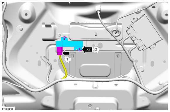
    Removal and Installation - Steering Column Control Module (SCCM)

    Removal NOTE: Removal steps in this procedure may contain installation details. NOTE: This step is only necessary when installing a new component...

    Other information:

    Ford Escape 2020-2024 Service Manual: Description and Operation - Electronic Engine Controls - Overview


    Overview The EEC system provides optimum control of the engine through the enhanced capability of the powertrain control module (PCM). The EEC system also has an on board diagnostic (OBD) monitoring system with features and functions to meet federal regulations on exhaust emissions...

    Ford Escape 2020-2024 Service Manual: Description and Operation - Jacking and Lifting - Overview


    Jacking and Lifting Points PHEV Only the specified jacking points may be used for jacking and supporting the vehicle. NOTICE: Make sure that no load is placed on the SOBDM . Jacking and Lifting Points All vehicles Only the specified jacking points may be used for jacking and supporting the vehicle...

    Categories

    Sitting in the Correct Position

    Ford Escape. Sitting in the Correct Position

    When you use them properly, the seat, head restraint, seatbelt and airbags will provide optimum protection in the event of a crash.

    read more

    Copyright © 2024 www.fordescape4.com