Ford Escape: Electronic Engine Controls / Removal and Installation - Crankshaft Position (CKP) Sensor
Special Tool(s) / General Equipment
.jpg) |
303-1699 Tool, Crank Sensor Alignment |
 |
303-507 Timing Peg, Crankshaft TDC TKIT-2001N-FLM TKIT-2001N-ROW |
| Ford Diagnostic Equipment | |
Removal
NOTICE: During engine repair procedures, cleanliness is extremely important. Any foreign material, including any material created while cleaning gasket surfaces, that enters the oil passages, coolant passages or the oil pan can cause engine failure.
-
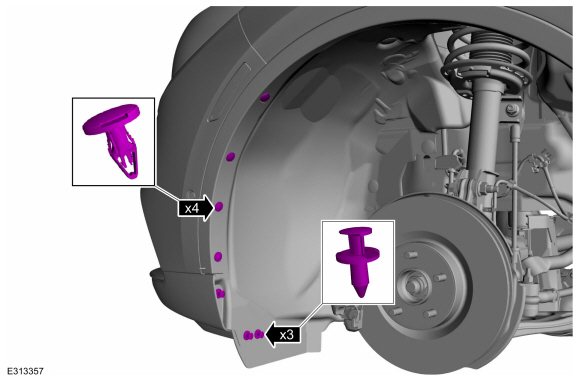
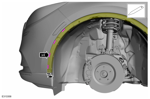
Remove the RHF front fender splash shield.
Refer to: Fender Splash Shield (501-02 Front End Body Panels, Removal and Installation).
-
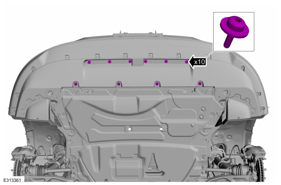
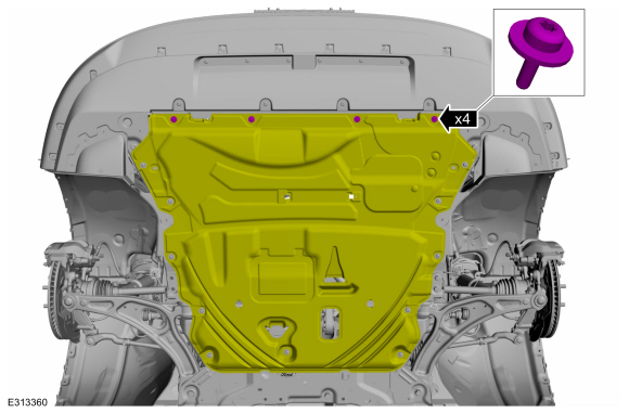
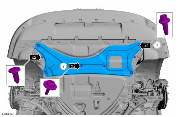
Remove the retainers and the engine undershield.
 |
-
Disconnect the CKP sensor electrical connector, remove the bolts and the CKP sensor.
 |
Installation
-
Turn the crankshaft clockwise until the No. 1 piston is 45 degrees BTDC
using the guide holes on the engine front cover and the crankshaft
pulley.
.jpg) |
-
Remove the engine plug bolt.
 |
- Install Special Service Tool: 303-507 Timing Peg, Crankshaft TDC.
 |
-
NOTE: The Crankshaft TDC Timing Peg will contact the crankshaft and prevent it from turning past TDC . However, the crankshaft can still be rotated in the counterclockwise direction. The crankshaft must remain at the TDC position during installation.
NOTE: The engine front cover is removed from graphic for clarity.
Rotate the crankshaft slowly until the crankshaft stops.
.jpg) |
-
NOTE: Do not tighten the CKP bolts at this time.
Install the CKP sensor and the bolts finger-tight.
.jpg) |
-
-
If the special service tool mark does not align with
the TDC (top dead center) marked tooth on the crankshaft pulley,
loosen the CKP sensor bolts and adjust the sensor until the tool is installed.
Use Special Service Tool: 303-1699 Tool, Crank Sensor Alignment.
-
Tighten the CKP sensor bolts.
Torque: 62 lb.in (7 Nm)
-
Remove the special tool.
Use Special Service Tool: 303-1699 Tool, Crank Sensor Alignment.
-
If the special service tool mark does not align with
the TDC (top dead center) marked tooth on the crankshaft pulley,
loosen the CKP sensor bolts and adjust the sensor until the tool is installed.
 |
-
Connect the CKP sensor electrical connector.
.jpg) |
- Remove Special Service Tool: 303-507 Timing Peg, Crankshaft TDC.
|
-
Install the engine plug bolt.
Torque: 177 lb.in (20 Nm)
|
-
Install the engine undershield and the retainers.
|
-
Install the RHF front fender splash shield.
Refer to: Fender Splash Shield (501-02 Front End Body Panels, Removal and Installation).
-
After completing the repair, use the scan tool to
perform the Misfire Monitor Neutral Profile Correction procedure,
following the on-screen instructions.
Use the General Equipment: Ford Diagnostic Equipment

 Removal and Installation - Cylinder Head Temperature (CHT) Sensor
Materials
Name
Specification
Motorcraft® Silicone Brake Caliper Grease and Dielectric CompoundXG-3-A
ESA-M1C200-AESE-M1C171-A
Removal
NOTE:
Removal steps in this procedure may contain installation details...
Other information:
Ford Escape 2020-2026 Owners Manual: Under Hood Overview - 1.5L EcoBoost™
Windshield washer fluid. See Adding Washer Fluid. Engine coolant reservoir. See Checking the Coolant. Engine oil dipstick. See Engine Oil Dipstick Overview. Engine oil filler cap. See Adding Engine Oil. Brake fluid reservoir. See Locating the Brake Fluid Reservoir...
Ford Escape 2020-2026 Service Manual: Removal and Installation - Battery Energy Control Module B (BECMB)
Removal WARNING: The following procedure prescribes critical repair steps required for correct restraint system operation during a crash. Follow all notes and steps carefully. Failure to follow step instructions may result in incorrect operation of the restraint system and increases the risk of serious personal injury or death in a crash...
Categories
- Manuals Home
- 4th Generation Ford Escape Owners Manual
- 4th Generation Ford Escape Service Manual
- Switching the Lane Keeping System On and Off. Switching the Lane Keeping System Mode. Alert Mode
- Locating the Pre-Collision Assist Sensors
- Rear View Camera
- New on site
- Most important about car
Symbols Glossary
These are some of the symbols you may see on your vehicle.
 Air conditioning system