Ford Escape 2020-2026 Service Manual / Powertrain / Engine / Engine Cooling / Diagnosis and Testing - Cooling Fan Control
Ford Escape: Engine Cooling / Diagnosis and Testing - Cooling Fan Control
Diagnostic Trouble Code (DTC) Chart
Diagnostics in this manual assume a certain skill level and knowledge of Ford-specific diagnostic practices.
REFER to: Diagnostic Methods (100-00 General Information, Description and Operation).
| Module | DTC | Description | Action |
|---|---|---|---|
| PCM | P0480:00 | Fan 1 Control Circuit: No Sub Type Information | GO to Pinpoint Test KN |
Global Customer Symptom Code (GCSC) Chart
Diagnostics in this manual assume a certain skill level and knowledge of Ford-specific diagnostic practices.
REFER to: Diagnostic Methods (100-00 General Information, Description and Operation).
| Symptom | Action |
|---|---|
| Start/Run/Move > Running > Overheats > Always | GO to Pinpoint Test KN |
| Start/Run/Move > Running > Overheats > Intermittent | GO to Pinpoint Test KN |
Pinpoint Tests
.jpg) PINPOINT TEST KN: VARIABLE SPEED ELECTRIC COOLING FAN MOTOR
PINPOINT TEST KN: VARIABLE SPEED ELECTRIC COOLING FAN MOTOR.jpg)
 Introduction Introduction
Refer to Wiring Diagrams Cell 033 for schematic and connector information. Normal Operation and Fault Conditions Refer to the DTC Fault Trigger Conditions. DTC Fault Trigger Conditions
Possible Sources
|
 Description and Operation - Engine Cooling - System Operation and Component Description
System Operation
Engine coolant flows primarily from the engine to the radiator circuit
and back to the coolant pump. Coolant is sent from the coolant pump
through the engine block and cylinder heads...
 Diagnosis and Testing - Engine Cooling
Special Tool(s)
Coolant/Battery RefractometerROB75240 or equivalent
D-Gas Adapter300-OTC014-R1068 or equivalent
Radiator Tester014-R1072 or equivalent
UView® Combustion Leak TesterUVU560000-R
Diagnostic Trouble Code (DTC) Chart
Diagnostics in this manual assume a certain skill level and knowledge of Ford-specific diagnostic prac..
Other information:
Ford Escape 2020-2026 Service Manual: Diagnosis and Testing - Parking Aid
Diagnostic Trouble Code (DTC) Chart Diagnostics in this manual assume a certain skill level and knowledge of Ford-specific diagnostic practices. REFER to: Diagnostic Methods (100-00 General Information, Description and Operation). Diagnostic Trouble Code Chart Module DTC Description Action PAM B1303..
Ford Escape 2020-2026 Service Manual: Removal and Installation - Turbocharger Oil Return Tube
Materials Name Specification Motorcraft® Metal Brake Parts CleanerPM-4-A, PM-4-B, APM-4-C - Removal NOTICE: The turbocharger compressor vanes can be damaged by even the smallest particles. When removing any turbocharger or engine air intake system component, ensure that no debris enters the system. Failure to do so may result in damage to the turbocharger. NOTIC..
Categories
- Manuals Home
- 4th Generation Ford Escape Owners Manual
- 4th Generation Ford Escape Service Manual
- Accessing the Trip Computer. Resetting the Trip Computer
- Rear View Camera
- Adjusting the Headlamps
- New on site
- Most important about car
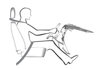
Sitting in the Correct Position

When you use them properly, the seat, head restraint, seatbelt and airbags will provide optimum protection in the event of a crash.
Copyright © 2026 www.fordescape4.com

.jpg) PINPOINT TEST KN: VARIABLE SPEED ELECTRIC COOLING FAN MOTOR
PINPOINT TEST KN: VARIABLE SPEED ELECTRIC COOLING FAN MOTOR

.png) Introduction
Introduction