Ford Escape: Suspension System - General Information / Diagnosis and Testing - Suspension System
Symptom Chart: Suspension System
Diagnostics in this manual assume a certain skill level and knowledge of Ford-specific diagnostic practices.
REFER to: Diagnostic Methods (100-00 General Information, Description and Operation).
| Condition | Actions |
|---|---|
| Wander | GO to Pinpoint Test A |
| Front bottoming or riding low | GO to Pinpoint Test B |
| Abnormal/incorrect tire wear | GO to Pinpoint Test C |
| Sticky steering, poor returnability | GO to Pinpoint Test D |
| Steering wheel off-center | GO to Pinpoint Test E |
| Sway or roll | GO to Pinpoint Test F |
| Vehicle leans to one side | GO to Pinpoint Test G |
| Vehicle drifts/pulls | GO to Pinpoint Test H |
- If an obvious cause for an observed or reported condition is found, correct the cause (if possible) before proceeding to the next step.
-
If the fault is not visually evident, REFER to Symptom Chart or REFER to NVH Symptom Chart.
REFER to: Noise, Vibration and Harshness (NVH) (100-04 Noise, Vibration and Harshness, Diagnosis and Testing).
Global Customer Symptom Code (GCSC) Chart
Diagnostics in this manual assume a certain skill level and knowledge of Ford-specific diagnostic practices.
REFER to: Diagnostic Methods (100-00 General Information, Description and Operation).
| Symptom | Action |
|---|---|
| Stop/Steer/Ride > Steering/Steering Wheel > Appearance/Clear Vision > Alignment | GO to Pinpoint Test E |
| Stop/Steer/Ride > Steering/Steering Wheel > Feel/Wander/Pull > High Speed | GO to Pinpoint Test A |
| Stop/Steer/Ride > Steering/Steering Wheel > Feel/Wander/Pull > High Speed | GO to Pinpoint Test H |
| Stop/Steer/Ride > Steering/Steering Wheel > Performance > Sticks/Binds | GO to Pinpoint Test D |
| Stop/Steer/Ride > Ride Quality > Lean/Height > Front | GO to Pinpoint Test G |
| Stop/Steer/Ride > Ride Quality > Soft/Float > Front | GO to Pinpoint Test F |
| Stop/Steer/Ride > Wheels/Tires/Spare > Tread Performance > Appearance | GO to Pinpoint Test C |
| Stop/Steer/Ride > Noise > Front > Over Bump | GO to Pinpoint Test B |
Pinpoint Tests
|
Normal Operation and Fault Conditions
REFER to: Suspension System (204-00 Suspension System - General Information, Diagnosis and Testing). Possible Sources
Visual Inspection and Pre-checks
|
||||
| A1 CHECK FOR SIGNS OF OVERLOADED, UNEVENLY, OR INCORRECTLY LOADED VEHICLE | ||||
Can signs of overloaded, uneven or incorrect vehicle load be determined?
|
||||
| A2 INSPECT THE BALL JOINTS FOR DAMAGE OR WEAR | ||||
Do the ball joints show signs of damage or excessive wear?
|
||||
| A3 INSPECT THE FRONT STRUT MOUNT BEARINGS | ||||
Do the front strut mount bearings show signs of damage or excessive wear?
|
||||
| A4 INSPECT THE FRONT WHEEL BEARINGS FOR LOOSENESS, DAMAGE OR WEAR | ||||
Do the front wheel bearing(s) show signs of looseness, wear or damage?
|
||||
| A5 CHECK FOR LOOSE, WORN OR DAMAGED FRONT SUSPENSION COMPONENTS | ||||
Do the front suspension components show signs of looseness, wear or damage?
|
||||
| A6 CHECK FOR LOOSE SUSPENSION FASTENERS | ||||
Are any loose fasteners noted?
|
||||
| A7 CHECK FOR LOOSE, WORN OR DAMAGED STEERING COMPONENTS | ||||
Do any steering system components show signs of looseness, wear or damage?
|
||||
| A8 VERIFY CORRECT WHEEL ALIGNMENT | ||||
Is the wheel alignment with specifications?
|
|
Normal Operation and Fault Conditions
REFER to: Suspension System (204-00 Suspension System - General Information, Diagnosis and Testing). Possible Sources
Visual Inspection and Pre-checks
|
||||
| B1 MEASURE THE VEHICLE RIDE HEIGHT | ||||
Is the vehicle ride height within specifications?
|
||||
| B2 CHECK FOR DAMAGED OR WORN FRONT STRUTS | ||||
Do the front struts show signs of excessive wear or damage?
|
|
Normal Operation and Fault Conditions
REFER to: Safety Precautions - Overview (204-04A Wheels and Tires, Description and Operation). Possible Sources
|
||||
| C1 VERIFY TIRE PRESSURES | ||||
Are the tire pressures within specifications?
|
||||
| C2 VERIFY THE TIRES HAVE BEEN ROTATED AT THE RECOMMENDED INTERVALS | ||||
Have the tires been rotated at the correct intervals?
|
||||
| C3 CHECK THE FRONT AND REAR WHEEL ALIGNMENT | ||||
Are the caster, camber and toe in within specifications?
|
||||
| C4 CHECK FOR LOOSE, WORN OR DAMAGED SUSPENSION COMPONENTS | ||||
Do any front or rear suspension components show signs of damage or wear?
|
|
Normal Operation and Fault Conditions
REFER to: Suspension System (204-00 Suspension System - General Information, Diagnosis and Testing). Possible Sources
|
||||
| D1 INSPECT THE FRONT STRUT MOUNT BEARINGS | ||||
Do the front strut mount bearings show signs of damage or excessive wear?
|
||||
| D2 INSPECT THE BALL JOINTS | ||||
Do the ball joints show signs of damage or excessive wear?
|
||||
| D3 CHECK FOR LOOSE, WORN OR DAMAGED STEERING COMPONENTS | ||||
Do any steering system components show signs of looseness, wear or damage?
|
|
Normal Operation and Fault Conditions
REFER to: Suspension System (204-00 Suspension System - General Information, Diagnosis and Testing). Possible Sources
|
||||
| E1 CHECK THE FRONT AND REAR WHEEL ALIGNMENT | ||||
Are the caster, camber and toe in within specifications?
|
||||
| E2 CHECK FOR LOOSE, WORN OR DAMAGED STEERING COMPONENTS | ||||
Do any steering system components show signs of looseness, wear or damage?
|
|
Normal Operation and Fault Conditions
REFER to: Suspension System (204-00 Suspension System - General Information, Diagnosis and Testing). Possible Sources
|
||||
| F1 CHECK FOR SIGNS OF OVERLOADED, UNEVENLY, OR INCORRECTLY LOADED VEHICLE | ||||
Can signs of overloaded, uneven or incorrect vehicle load be determined?
|
||||
| F2 INSPECT THE WHEEL NUTS | ||||
Are any of the wheel nuts loose?
|
||||
| F3 INSPECT STRUTS AND SHOCK ABSORBERS | ||||
Do the struts and shock absorbers show signs of leakage, damage or excessive wear?
|
||||
| F4 INSPECT THE STABILIZER BRACKET TO FRAME BOLTS | ||||
Are all of the fasteners tightened to specification?
|
||||
| F5 INSPECT THE STABILIZER BAR BUSHINGS AND LINKS FOR DAMAGE OR EXCESSIVE WEAR | ||||
Do the bushings or links show signs of damage or excessive wear?
|
||||
| F6 INSPECT THE STABILIZER BAR | ||||
Is the stabilizer bar damaged or broken?
|
||||
| F7 INSPECT THE SPRINGS FOR DAMAGE OR EXCESSIVE WEAR | ||||
Are any of the springs damaged or worn?
|
|
Normal Operation and Fault Conditions
REFER to: Suspension System (204-00 Suspension System - General Information, Diagnosis and Testing). Possible Sources
|
||||
| G1 CHECK FOR SIGNS OF OVERLOADED, UNEVENLY, OR INCORRECTLY LOADED VEHICLE | ||||
Can signs of overloaded, uneven or incorrect vehicle load be determined?
|
||||
| G2 CHECK FOR LOOSE, WORN OR DAMAGED FRONT SUSPENSION COMPONENTS | ||||
Do the front suspension components show signs of looseness, wear or damage?
|
||||
| G3 MEASURE THE VEHICLE RIDE HEIGHT | ||||
Is the vehicle ride height within specifications?
|
|
Normal Operation and Fault Conditions
REFER to: Suspension System (204-00 Suspension System - General Information, Diagnosis and Testing). Possible Sources
|
||||
| H1 CHECK FOR VEHICLE PULL/DRIFT | ||||
Does the vehicle pull or drift?
|
Component Tests
Ball Joint Inspection
-
Prior to inspecting the ball joints for wear, inspect
the wheel bearings. Install a new wheel bearing as necessary. Wheel
Bearing and Wheel Hub
REFER to: Front Wheel Bearing and Wheel Hub (204-01 Front Suspension, Removal and Installation).
-
NOTE: In order to obtain accurate measurements, the suspension must be in full rebound with the weight of the vehicle supported by the frame.
Raise and support the vehicle by the frame to allow the wheels to hang in the rebound position.
REFER to: Jacking and Lifting - Overview (100-02 Jacking and Lifting, Description and Operation).
-
Inspect the ball joint and ball joint boot for damage.
-
If the ball joint or ball joint boot is damaged, install a new lower control arm as necessary.
REFER to: Lower Arm (204-01 Front Suspension, Removal and Installation).
-
If the ball joint or ball joint boot is damaged, install a new lower control arm as necessary.
NOTE: Carry out Steps 4 through 6 to inspect the lower ball joint.
-
NOTICE: Do not use any tools or equipment to move the wheel and tire assembly or suspension components while checking for relative movement. Suspension damage may occur. The use of tools or equipment will also create relative movement that may not exist when using hand force. Relative movement must be measured using hand force only.
NOTE: The weight of the wheel and tire assembly must be overcome to obtain an accurate measurement on the dial indicator.
Inspect the ball joint for relative movement by alternately pulling downward and pushing upward on the lower control arm by hand. Note any relative vertical movement between the wheel knuckle and lower control arm at the lower ball joint.
-
If relative movement is not felt or seen, the ball joint is OK. Do not install a new lower control arm.
-
If relative movement is found, continue with Step 5.
-
If relative movement is not felt or seen, the ball joint is OK. Do not install a new lower control arm.
-
NOTE: In order to obtain an accurate measurement, the dial indicator should be aligned as close as possible with the vertical axis (center line) of the ball joint.
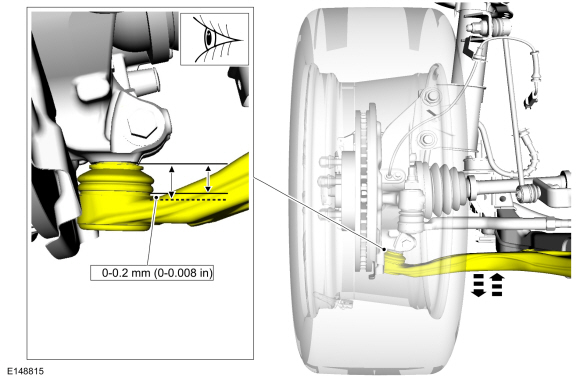
To measure ball joint deflection, attach a suitable dial indicator with a flexible arm between the lower control arm and the wheel knuckle or ball joint stud.
-
Measure the ball joint deflection while an assistant pushes up and pulls down on the lower control arm, by hand.
-
If the deflection exceeds the specification, a new lower control arm must be installed.
REFER to: Lower Arm (204-01 Front Suspension, Removal and Installation).
-
If the deflection meets the specification, no further action is required.
-
If the deflection exceeds the specification, a new lower control arm must be installed.
 Specifications
General Specifications
Item
Specification
Ball Joint Deflection
Lower
0-0.2 mm (0-0...
 General Procedures - Front Toe Adjustment
Special Tool(s) /
General Equipment
Wheel Alignment System
Adjustment
NOTE:
Make sure that the vehicle is standing on a level surface.
NOTE:
Before carrying out a toe adjustment, check the tires for
the correct pressure...
Other information:
Ford Escape 2020-2026 Service Manual: General Procedures - Transmission Fluid Level Check
Materials Name Specification Motorcraft® MERCON® ULV Automatic Transmission FluidXT-12-QULV WSS-M2C949-A, MERCON® ULV Check Start the engine and allow to run for 1 minute. Turn engine off and wait 5 minutes. With the vehicle in NEUTRAL, position it on a hoist...
Ford Escape 2020-2026 Service Manual: Diagnosis and Testing - Seatbelt Systems
Symptom Chart(s) Preliminary Inspection Diagnostics in this manual assume a certain skill level and knowledge of Ford-specific diagnostic practices. REFER to: Diagnostic Methods (100-00 General Information, Description and Operation). Before diagnosing or repairing the seatbelt system, inspect the following items: Seatbelt webbing integrity (torn, frayed, cut or stretched) Seatb..
Categories
- Manuals Home
- 4th Generation Ford Escape Owners Manual
- 4th Generation Ford Escape Service Manual
- General Procedures - Transmission Fluid Level Check
- Electric Parking Brake
- Locating the Pre-Collision Assist Sensors
- New on site
- Most important about car
Master Access Code
What Is the Master Access Code
The master access code is a factory-set five-digit entry code. You can operate the keypad with the master access code at any time. The master access code is on the owner’s wallet card in the glove box and is available from an authorized dealer.
Displaying the Master Access Code
To display the factory-set code in the information display:
