Ford Escape: Automatic Transmission - Automatic Transmission – HF45 / Disassembly - Transmission - Plug-In Hybrid Electric Vehicle (PHEV)
Special Tool(s) /
General Equipment
 |
307-163
(T86P-70043-A)
Remover, Stator Case Bearing
TKIT-1986-LM
TKIT-1986-F |
 |
307-586
Differential bearing cup remover
TKIT-2006UF-FLM
TKIT-2006UF-ROW |
 |
307-741
Spring Compressor, F Clutch |
 |
307-821
Motor Rotor Remover Installer |
 |
308-001
(T58L-101-B)
Remover, Pilot Bearing |
| Hydraulic Press |
| Puller |
| Punch |
| Wooden Block |
-
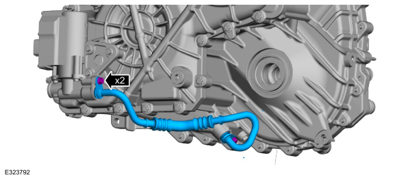
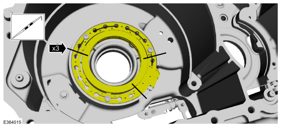
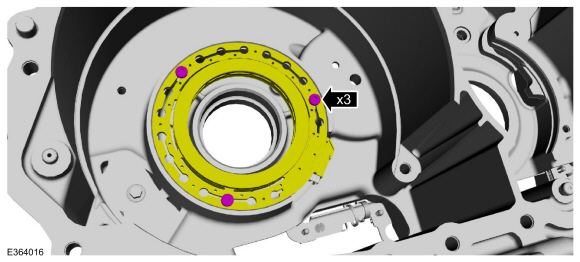
Remove the bolts the and transmission fluid tube.
-
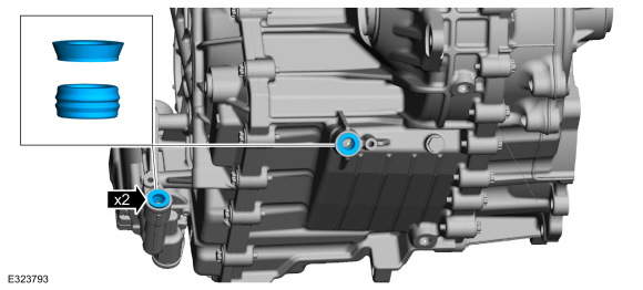
Inspect the transmission and the auxiliary pump to be sure
the transmission fluid tube seal and backing ring were removed with the
transmission fluid tube and are not stuck in the transmission or
auxiliary pump. If the transmission fluid tube seal or backing ring are
stuck in the transmission or auxiliary pump, remove the seal and backing
ring.
-
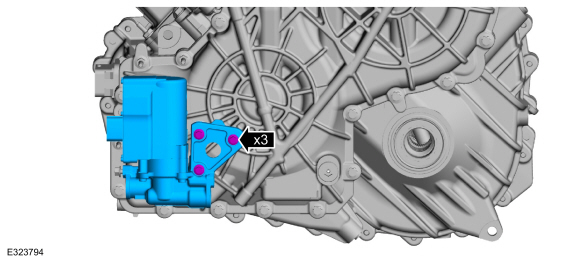
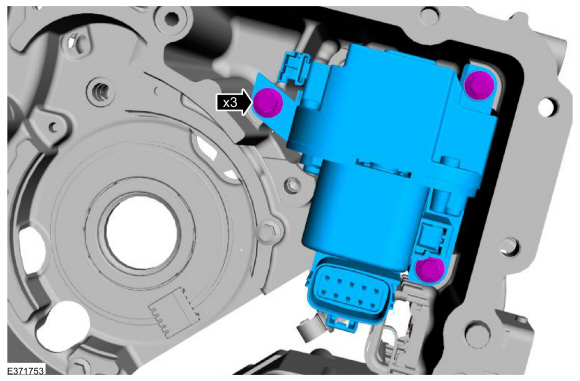
Remove the bolts and the transmission fluid auxiliary pump.
-
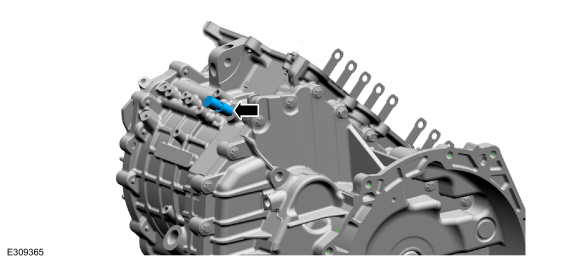
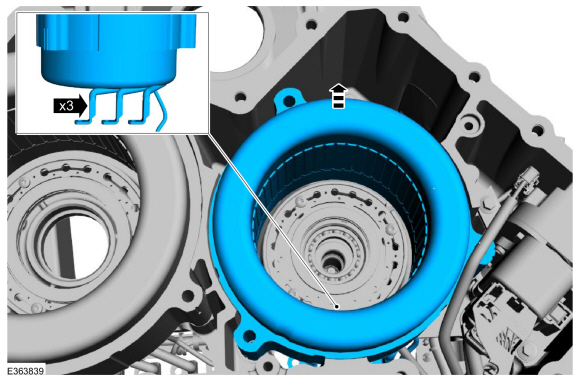
Remove the vent assembly.
-
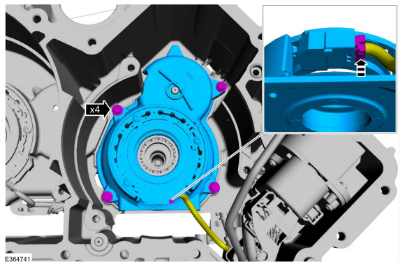
NOTE:
Note the location of the stud bolts for assembly.
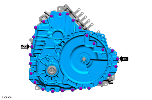
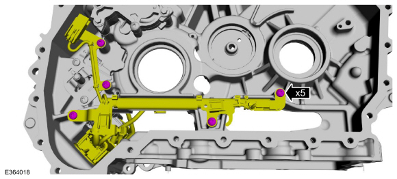
Remove the damper housing bolts and the studbolts.
-
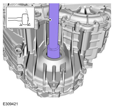
Using a prybar, pry the damper housing at the indicated areas to remove the housing.
-
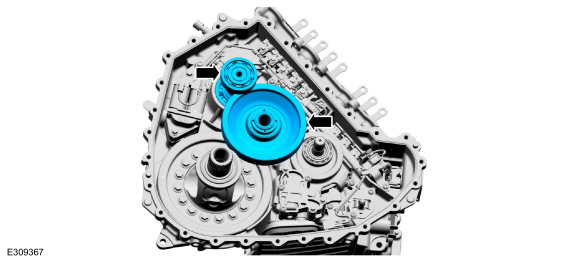
Remove the transfer shaft gear assembly and the traction motor drive gear assembly.
-
Replace the transfer shaft and gear assembly and install new bearing races if the bearings are damaged.
-
Replace the transfer shaft and gear assembly and install new bearings if the bearings are damaged.
-
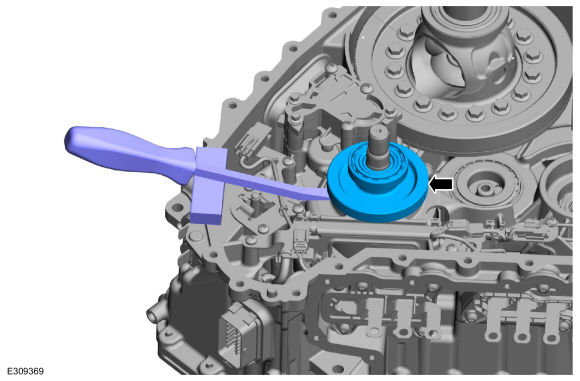
Using a prybar and a block of wood, remove the final drive input gear assembly.
Use the General Equipment: Wooden Block
-
Replace the final drive input gear assembly if the bearings are damaged.
-
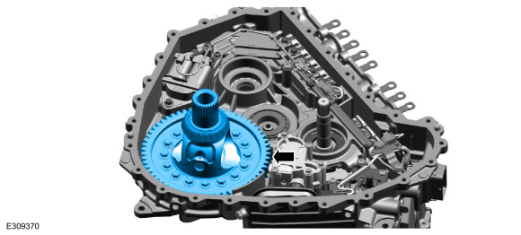
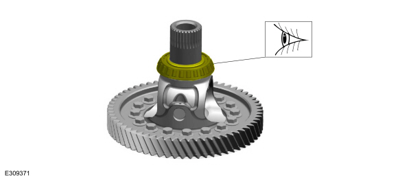
Remove the differential carrier gear assembly.
-
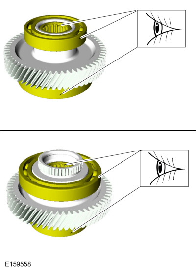
Inspect the differential bearing for damage, replace if necessary.
-
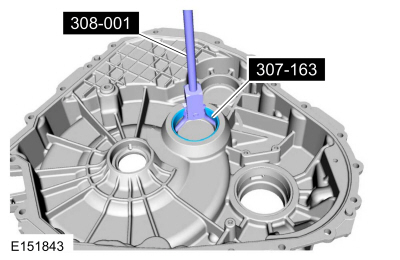
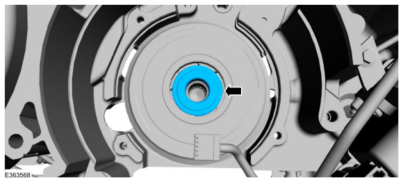
Using the special tools, remove the transmission case side transfer gear bearing cup.
Use Special Service Tool: 308-001
(T58L-101-B)
Remover, Pilot Bearing.
, 307-163
(T86P-70043-A)
Remover, Stator Case Bearing.
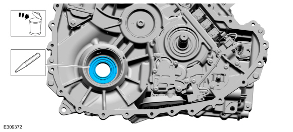
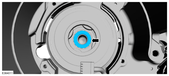
-
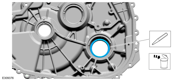
Remove and discard the LH halfshaft seal.
Use the General Equipment: Punch
-
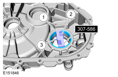
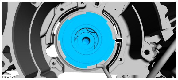
-
Position the Differential Bearing Cup Remover 307-586 in
the transmission case with the tabs on the Differential Bearing Cup
Remover 307-586 aligned with the slots in the transmission case.
Use Special Service Tool: 307-586
Differential bearing cup remover.
-
Expand the Differential Bearing Cup Remover 307-586 by hand.
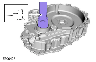
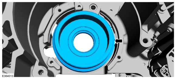
-
While holding the Differential Bearing Cup Remover
307-586 in the expanded position with the tabs in the slots of the
transmission case, tighten the nut.
-
Using a hammer and a drift, remove the differential bearing cup.
Use Special Service Tool: 307-586
Differential bearing cup remover.
-
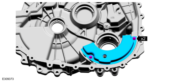
Remove the retainers and the transmission fluid sump baffle.
-
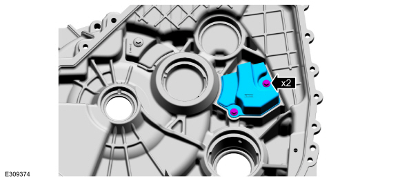
Remove the retainers and the transmission fluid collector plate.
-
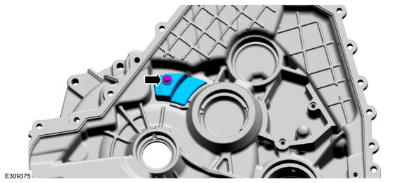
Remove the retainer and the transmission fluid collector plate.
-
Remove and discard the RH halfshaft seal.
Use the General Equipment: Punch
-
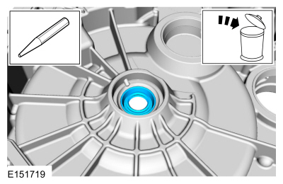
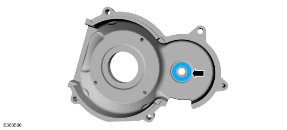
Remove and discard the input shaft seal.
Use the General Equipment: Punch
-
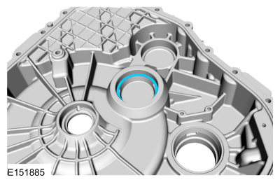
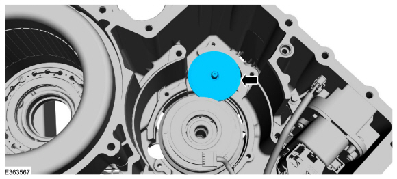
Remove the damper housing side transfer gear bearing cup.
Use Special Service Tool: 308-001
(T58L-101-B)
Remover, Pilot Bearing.
, 307-163
(T86P-70043-A)
Remover, Stator Case Bearing.
-
Remove the transfer shaft preload shim.
-
-
Position the Differential Bearing Cup Remover 307-586 in
the damper housing with the tabs on the Differential Bearing Cup
Remover 307-586 aligned with the slots in the damper housing.
Use Special Service Tool: 307-586
Differential bearing cup remover.
-
Expand the Differential Bearing Cup Remover 307-586 by hand.
-
While holding the Differential Bearing Cup Remover
307-586 in the expanded position with the tabs in the slots of the
damper housing, tighten the nut.
-
Using a hammer and a drift, remove the damper housing side differential bearing cup.
Use Special Service Tool: 307-586
Differential bearing cup remover.
-
Remove the differential preload shim.
-
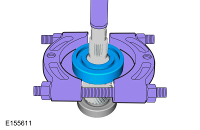
Remove the traction motor drive gear rear bearing from the traction motor drive gear.
Use the General Equipment: Puller
Use the General Equipment: Hydraulic Press
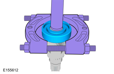
-
Remove the traction motor drive gear front bearing from the traction motor drive gear.
Use the General Equipment: Puller
Use the General Equipment: Hydraulic Press
-
Remove the transmission high voltage terminals.
Refer to: Transmission High Voltage Terminals (307-01B Automatic
Transmission - Automatic Transmission – HF45, Disassembly and Assembly
of Subassemblies).
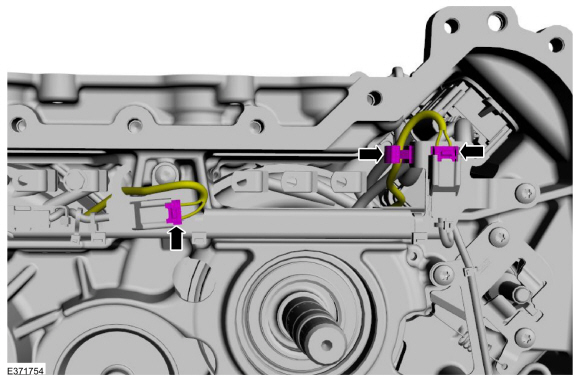
-
-
Disconnect the traction motor stator electrical connector.
-
Disconnect the generator/starter stator electrical connector.
-
Detach the wiring retainer.
-
Position the transmission case on blocks of wood so the transmission input shaft doesn't contact the table surface.
-
Remove the transmission case cover.
Refer to: Transmission Case Cover (307-01B Automatic Transmission - Automatic Transmission – HF45, Removal and Installation).
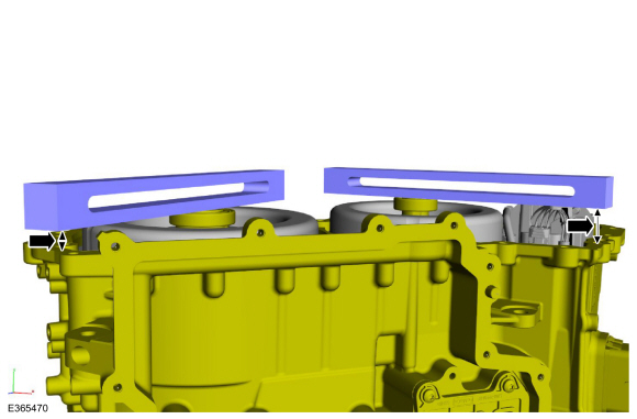
-
Using a straight edge, measure and record the distance
between the traction motor rotor and the transmission case surface. Then
measure and record the distance between the generator/starter rotor and
transmission case surface for reassembly.
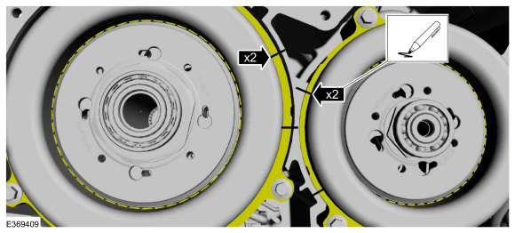
-
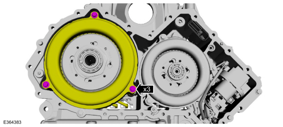
Mark the traction motor stator and the generator/starter
stator with the transmission case as indicated for correct installation.
-
Remove the traction motor stator bolts.
-
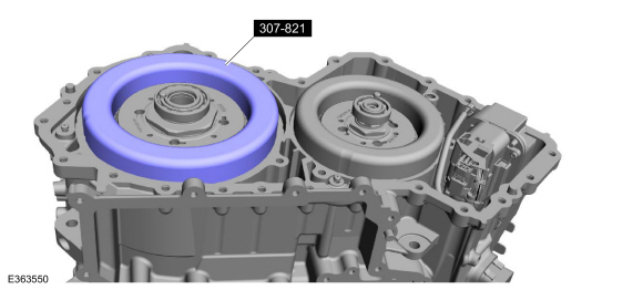
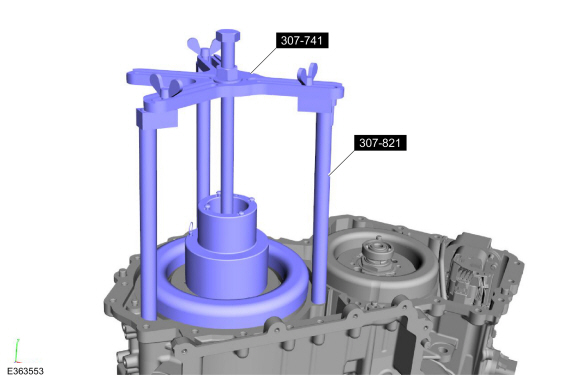
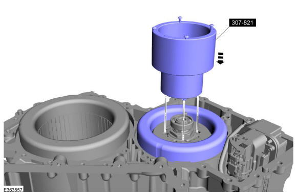
Install the special tool on the traction motor stator windings.
Use Special Service Tool: 307-821
Motor Rotor Remover Installer.
-
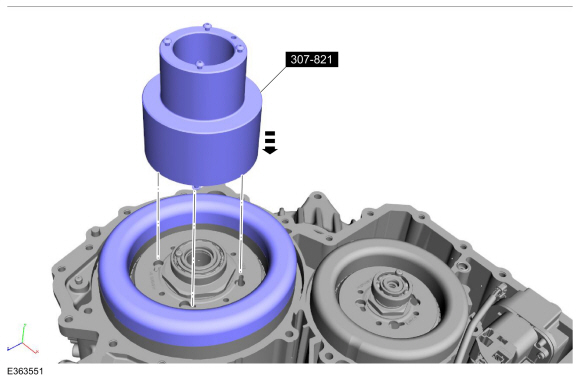
Install the special tool in the traction motor rotor slotted
holes and rotate counter-clockwise until special tool is secured.
Use Special Service Tool: 307-821
Motor Rotor Remover Installer.
-
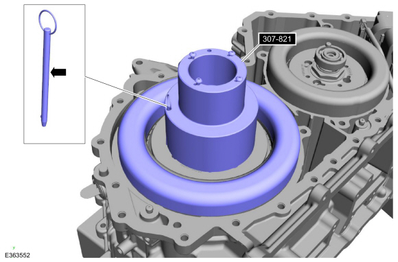
Install the pin in the special tool until it is fully seated in the rotor.
Use Special Service Tool: 307-821
Motor Rotor Remover Installer.
-
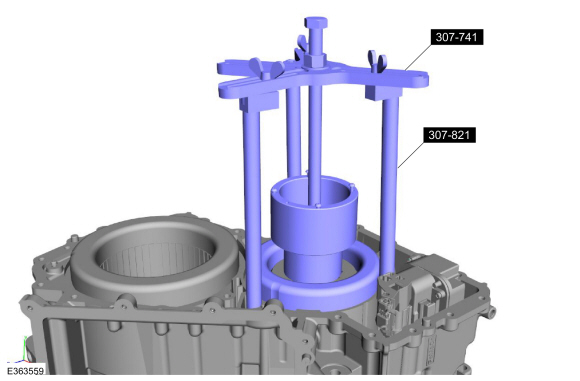
Install the special tools, thread draw bolt into special tool and tighten the wing nuts.
Use Special Service Tool: 307-741
Spring Compressor, F Clutch.
, 307-821
Motor Rotor Remover Installer.
-
NOTICE:
Rotors are magnetized, only place rotors on a nonmetallic tray.
-
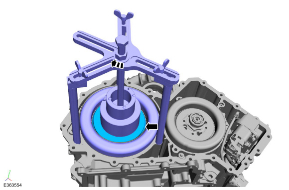
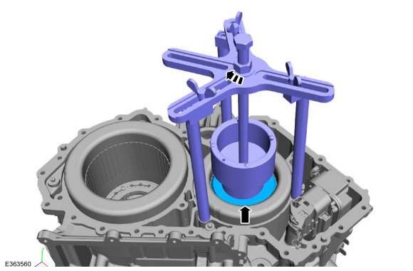
Remove the traction motor rotor by turning the nut on the draw bar.
-
When the rotor starts to turn in the stator, lift up on the special tool to remove the rotor.
-
Remove the generator/starter stator bolts.
-
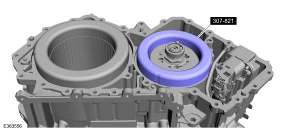
Install the special tool on the generator/starter stator windings.
Use Special Service Tool: 307-821
Motor Rotor Remover Installer.
-
Install the special tool in the generator/starter rotor
slotted holes and rotate counter-clockwise until special tool is
secured.
Use Special Service Tool: 307-821
Motor Rotor Remover Installer.
-
Install the pin in the special tool until it is fully seated in the rotor.
Use Special Service Tool: 307-821
Motor Rotor Remover Installer.
-
Install the special tools, thread draw bolt into special tool and tighten the wing nuts.
Use Special Service Tool: 307-741
Spring Compressor, F Clutch.
, 307-821
Motor Rotor Remover Installer.
-
NOTICE:
Rotors are magnetized, only place rotors on a
nonmetallic tray. Do not let the traction rotor and the
generator/starter rotor come in contact with each other or damage may
occur.
-
Remove the generator/starter rotor by turning the nut on the draw bar clockwise.
-
When the rotor starts to turn in the stator, lift up on the special tool to remove the rotor.
-
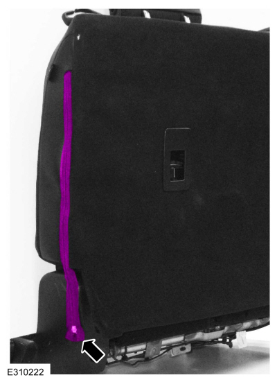
-
If equipped, cut and discard the tie strap.
-
Disconnect the park lock actuator.
-
NOTICE:
When removing the stator be careful not to bend or break the stator wires.
NOTICE:
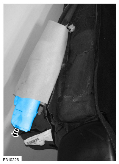
After removing the stator, lay the stator on its side or damage to the windings may occur.
Remove the generator/starter stator.
-
Remove the planetary carrier support cover bolts, disconnect
the generator/starter resolver and remove the support cover.
-
Remove thrust washer from the planetary carrier support cover.
-
Remove the pump drive gear.
-
Remove the sun gear.
-
Remove the sun gear thrust bearing.
-
Remove the planetary carrier assembly.
-
NOTE:
Leave bearing inside ring gear.
Remove the ring gear.
-
NOTICE:
When removing the stator be careful not to bend or break the stator wires.
NOTICE:
After removing the stator, lay the stator on its side or damage to the windings may occur.
Rotate the transmission case on its side and remove the traction motor stator.
-
NOTE:
Only remove the traction motor resolver if it is necessary to clean debris from under the sensor.
Using a metal scriber, mark the traction motor resolver with
the transmission case as indicated for correct installation.
-
Remove the traction motor resolver bolts.
-
NOTE:
Lift up on the resolver and rotate to access the electrical connector.
Disconnect and remove the traction motor resolver.
-
Disconnect the park lock actuator.
-
Remove the bolts and the park lock actuator.
-
Rotate the transmission case and position the case on blocks of wood.
-
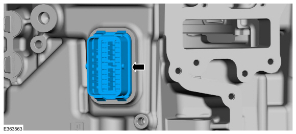
Remove the wiring harness bolts.
-
Remove the wiring harness bulkhead connector and the wiring harness from the transmission.
-
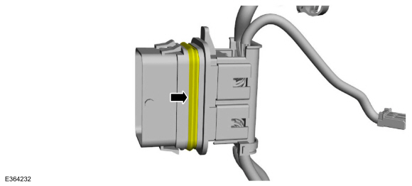
Inspect the wiring harness bulkhead seal for damage, replace if necessary.
-
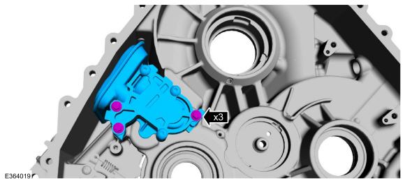
Remove the bolts and the fluid pump and filter assembly.
-
-
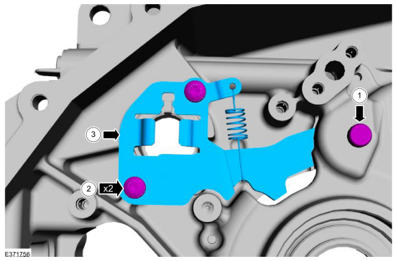
Remove the park pawl shaft.
-
Remove the park lock actuator guide bolts.
-
Remove the park lock actuator guide and park pawl.
Special Tool(s) /
General Equipment
204-069
(T81P-1104-C)
Remover/Installer, Front Wheel Hub
307-587Differential bearing installer and guideTKIT-2006UF-FLMTKIT-2006UF-ROW
307-791Install, Differential Bearing (AWD)
Hydraulic Press
Puller
DISASSEMBLY
Inspect the differential bearings for damage or excessive wear...
Other information:
System Operation
System Diagram - Gauges
Gas
Item
Description
1
GWM
2
IPC
3
PCM
4
Fuel pump and sender unit
5
Base/mid-level analog gauges
6
Temperature
7
Fuel
8
Speedometer
9
Tachometer
10
AWD
11
Base level virtual gauge
12
AWD
13
Mid-level virtual gauges
14
Fuel
..
Removal
NOTE:
Removal steps in this procedure may contain installation details.
Release the clips and remove the trim panel.
Remove the bolts and the display unit.
Disconnect the electrical connector.
Torque:
22 lb.in (2.5 Nm)
Remove the bolts, release the clips and remove the center instrument panel t..
Categories
What Is the Master Access Code
The master access code is a factory-set
five-digit entry code. You can operate the
keypad with the master access code at
any time. The master access code is on the
owner’s wallet card in the glove box and
is available from an authorized dealer.
Displaying the Master Access Code
To display the factory-set code in the
information display:

Remove the rubber mat.
Insert the first programmed key in the
backup slot.
Press the push button ignition switch
once and wait a few seconds.
Press the push button ignition switch
again and remove the key.
Within 10 seconds, place a second
programmed intelligent access key in
the backup slot and press the push
button ignition switch.
read more
.jpg)
.jpg)
.jpg)
.jpg)
.jpg)
.jpg)
.jpg)
.jpg)
.jpg)
.jpg)

 Disassembly and Assembly of Subassemblies - Differential