
Ford Escape 2020-2026 Service Manual / Powertrain / Automatic Transmission
Ford Escape: Powertrain / Automatic Transmission
- Automatic Transmission - Automatic Transmission – HF45
- Transmission Cooling - Automatic Transmission – HF45
- Automatic Transmission External Controls - Automatic Transmission – HF45
- Four-Wheel Drive Systems
- Power Transfer Unit


Other information:
Ford Escape 2020-2026 Service Manual: Description and Operation - Airbag and Seatbelt Pretensioner Supplemental Restraint System (SRS) - Overview
Overview The RCM continually receives and monitors inputs from the OCSM and various other hard-wired switches and sensors. If the RCM detects a sudden vehicle deceleration and/or lateral deceleration based on the information received from the various sensors and determines that deployment is necessary, it applies voltage and current to deploy the appropriate SRS components. The SRS utilizes..
Ford Escape 2020-2026 Service Manual: Removal and Installation - Hood Latch Release Handle
Removal Remove the hood latch release handle. Rotate the hood latch release handle. NOTE: Do not remove the retaining clip from the hood latch release handle. Release the retaining clip. Remove the hood latch release handle. Installation To install, reverse the removal procedure. ..
Categories
- Manuals Home
- 4th Generation Ford Escape Owners Manual
- 4th Generation Ford Escape Service Manual
- Adjusting the Headlamps
- General Procedures - Brake Service Mode Activation and Deactivation
- Fuel Quality
- New on site
- Most important about car
Under Hood Fuse Box
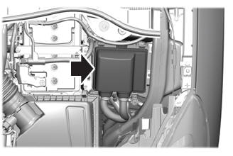
Locating the Under Hood Fuse Box
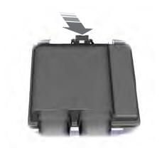
Accessing the Under Hood Fuse Box

Copyright © 2026 www.fordescape4.com