Ford Escape: Supplemental Restraint System / General Procedures - Clockspring Adjustment
Special Tool(s) / General Equipment
| Adhesive Tape |
.jpg) WARNING:
If the clockspring is not correctly centralized, it may fail
prematurely. If in doubt, repeat the centralizing procedure. Failure to
follow these instructions may increase the risk of serious personal
injury or death in a crash.
WARNING:
If the clockspring is not correctly centralized, it may fail
prematurely. If in doubt, repeat the centralizing procedure. Failure to
follow these instructions may increase the risk of serious personal
injury or death in a crash.
NOTE: Typical clockspring shown, others similar.
-
NOTICE: Do not over-rotate the clockspring rotor. The internal ribbon wire is connected to the clockspring rotor. The internal ribbon wire acts as a stop and can be broken from its internal connection. Failure to follow this instruction may result in component damage and/or system failure.
Turn the clockspring rotor clockwise, carefully feeling for resistance to turning.
 |
-
NOTE: The clockspring rotor must stop at the first instance that the electrical connector is at the 12 o'clock position.
Turn the clockspring rotor counterclockwise so the electrical connector is in the 12 o'clock position.
.jpg) |
-
NOTE: After final positioning, do not allow the clockspring rotor to rotate from this position.
Turn the clockspring rotor counterclockwise through 3 complete turns ending with the clockspring rotor electrical connector in the 12 o'clock position.
.jpg) |
-
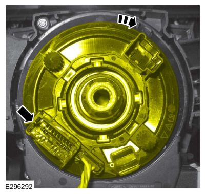
When the clockspring is correctly centralized, the wiring
harness is visible through the site glass and the 2 arrows at the LH
side are aligned. Make sure the clockspring does not rotate from this
position until after the steering wheel is installed.
.jpg) |
-
Tape the clockspring inner rotor to the outer housing.
Use the General Equipment: Adhesive Tape
 |
 Diagnosis and Testing - Airbag Supplemental Restraint System (SRS)
Diagnostic Trouble Code (DTC) Chart
Diagnostics in this manual assume a certain skill level and knowledge of Ford-specific diagnostic practices.REFER to: Diagnostic Methods (100-00 General Information, Description and Operation)...
 General Procedures - Inspection and Repair after a Supplemental Restraint System (SRS) Deployment
Inspection
WARNING:
If a vehicle has been in a crash, inspect the Restraints
Control Module (RCM) and impact sensor mounting areas for any damage or
deformation...
Other information:
Ford Escape 2020-2026 Service Manual: Removal and Installation - Accessory Drive Belt - Vehicles Built Up To: 1-October-2020
Special Tool(s) / General Equipment 5 mm Drill Bit Removal NOTE: Removal steps in this procedure may contain installation details. Refer to: Health and Safety Precautions (100-00 General Information, Description and Operation)...
Ford Escape 2020-2026 Service Manual: Removal and Installation - A-Pillar Trim Panel
Special Tool(s) / General Equipment Interior Trim Remover Removal NOTE: LH (left hand) shown, RH (right hand) similar. Disconnect the tether clips from the A-pillar trim panel. Release the A-pillar trim panel clip from the tether clips...
Categories
- Manuals Home
- 4th Generation Ford Escape Owners Manual
- 4th Generation Ford Escape Service Manual
- Rear View Camera
- Switching the Rear Window Wiper On and Off. Reverse Wipe
- Child Safety Locks
- New on site
- Most important about car
Symbols Glossary
These are some of the symbols you may see on your vehicle.
 Air conditioning system