Ford Escape: Fuel System - General Information / General Procedures - Fuel Tank Draining
Special Tool(s) / General Equipment
 |
292-00004 Fuel Tanker 100 GPM |
Draining
.jpg)
.jpg)
.jpg)
-
Refer to: Gasoline and Gasoline-Ethanol Fuel Systems Health and Safety Precautions (100-00 General Information, Description and Operation)..jpg) WARNING:
Before beginning any service procedure in this
section, refer to Safety Warnings in section 100-00 General Information.
Failure to follow this instruction may result in serious personal
injury.
WARNING:
Before beginning any service procedure in this
section, refer to Safety Warnings in section 100-00 General Information.
Failure to follow this instruction may result in serious personal
injury.
-
Disconnect the battery ground cable.
Refer to: Battery Disconnect and Connect (414-01 Battery, Mounting and Cables, General Procedures).
-
With the vehicle in NEUTRAL, position it on a hoist.
Refer to: Jacking and Lifting - Overview (100-02 Jacking and Lifting, Description and Operation).
-
-
NOTE: The supplemental refueling adapter is located in the luggage compartment.
Install the supplemental refueling adapter and a length of semi-rigid fuel drain tube into the Easy Fuel (capless) fuel tank filler pipe.
-
Attach the Fuel Storage Tanker to the fuel drain
tube and drain as much fuel as possible from the Easy Fuel (capless)
fuel tank filler pipe, lowering the fuel level below the fuel tank inlet
spout.
-
.jpg) |
-
.jpg)

NOTICE: Only use the specified general equipment.
NOTE: Be prepared to collect escaping fulid.
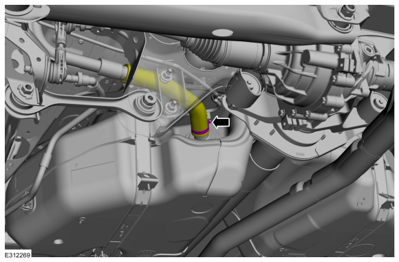
NOTE: wrap the fuel line connector with a shop towel to absorb any residual fuel pressure during the removal of the fuel line.
Loosen the clamp and disconnect the hose. Position the hose aside.
Torque: 33 lb.in (3.7 Nm)
 |
-
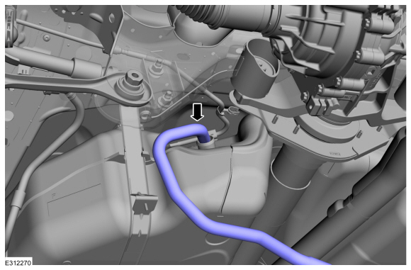
NOTICE: Make sure the open end of the hose is secured above the fluid level in the reservoir.
NOTICE: Use suitable paper absorb any escaping fluid.
Insert the hose from the fuel storage tanker and siphon the fuel through the hose.
Use Special Service Tool: 292-00004 Fuel Tanker 100 GPM.
 |
 Diagnosis and Testing - Fuel System
Diagnostic Trouble Code (DTC) Chart
Diagnostics in this manual assume a certain skill level and knowledge of Ford-specific diagnostic practices.REFER to: Diagnostic Methods (100-00 General Information, Description and Operation)...
 General Procedures - Fuel System Pressure Check
Special Tool(s) /
General Equipment
310-D009
(D95L-7211-A)
Fuel Pressure Test Kit
Check
WARNING:
Before beginning any service procedure in this section,
refer to Safety Warnings in section 100-00 General Information...
Other information:
Ford Escape 2020-2026 Service Manual: Removal and Installation - Hood
Removal NOTE: Removal steps in this procedure may contain installation details. Remove the retainers and the hood insulation. Detach the windshield washer hose coupling. Detach the retainers and position aside the windshield washer hose from the hood...
Ford Escape 2020-2026 Service Manual: Removal and Installation - Ambient Air Temperature Sensor
Removal NOTE: Removal steps in this procedure may contain installation details. With the vehicle in NEUTRAL, position it on a hoist. Refer to: Jacking and Lifting - Overview (100-02 Jacking and Lifting, Description and Operation). Disconnect the electrical connector...
Categories
- Manuals Home
- 4th Generation Ford Escape Owners Manual
- 4th Generation Ford Escape Service Manual
- Drive Modes
- Switching the Rear Window Wiper On and Off. Reverse Wipe
- Electric Parking Brake
- New on site
- Most important about car
Push Button Ignition Switch

Switching the Ignition Off
When the ignition is on or in accessory mode, press the push button ignition switch once without your foot on the brake pedal.