Ford Escape: Side Panel Sheet Metal Repairs / Removal and Installation - B-Pillar Outer Panel
Special Tool(s) / General Equipment
| Resistance Spotwelding Equipment | |
| Spherical Cutter | |
| Hot Air Gun | |
| Air Body Saw | |
| 8 mm Drill Bit | |
| MIG/MAG Welding Equipment | |
| Spot Weld Drill Bit | |
| Locking Pliers |
Materials
| Name | Specification |
|---|---|
| Metal Bonding Adhesive TA-1, TA-1-B, 3M™ 08115, LORD Fusor® 108B, Henkel Teroson EP 5055 |
- |
| Flexible Foam Repair 3M™ 08463, LORD Fusor® 121 |
- |
Removal
 WARNING:
Electric vehicles damaged by a crash may have compromised
high voltage safety systems and present a potential high voltage
electrical shock hazard. Exercise caution and wear appropriate Personal
Protective Equipment (PPE) safety gear, including high voltage safety
gloves and boots. Remove all metallic jewelry, including watches and
rings. Isolate the HV system as directed by the Ford Emergency Response
Guide for the vehicle. Failure to follow these instructions may result
in serious personal injury or death.
WARNING:
Electric vehicles damaged by a crash may have compromised
high voltage safety systems and present a potential high voltage
electrical shock hazard. Exercise caution and wear appropriate Personal
Protective Equipment (PPE) safety gear, including high voltage safety
gloves and boots. Remove all metallic jewelry, including watches and
rings. Isolate the HV system as directed by the Ford Emergency Response
Guide for the vehicle. Failure to follow these instructions may result
in serious personal injury or death.
NOTICE: Battery electric vehicle (BEV), hybrid electric vehicle (HEV) and plug-in hybrid electric vehicle (PHEV) contain a high-voltage battery. Before cutting or welding near the high-voltage battery it must be removed to avoid damage.
NOTE: Left hand (LH) side shown, right hand (RH) side similar.
-
Refer to: Health and Safety Precautions (100-00 General Information, Description and Operation).
WARNING:
Before beginning any service procedure in this
manual, refer to health and safety warnings in section 100-00 General
Information. Failure to follow this instruction may result in serious
personal injury.
Refer to: High Voltage System Health and Safety Precautions - Overview (100-00 General Information, Description and Operation).
-
Depower the SRS .
Refer to: Supplemental Restraint System (SRS) Depowering (501-20B Supplemental Restraint System, General Procedures).
-
If Necessary:
Restore the vehicle dimensionally to pre-accident condition.
Refer to: Body and Frame (501-26 Body Repairs - Vehicle Specific Information and Tolerance Checks, Description and Operation).
-
Remove the rocker panel moulding.
Refer to: Rocker Panel Moulding (501-08 Exterior Trim and Ornamentation, Removal and Installation).
-
Remove the rear door.
Refer to: Rear Door (501-03 Body Closures, Removal and Installation).
-
Remove the front and rear door opening tread plates.
-
Remove the front and rear door opening weather strips.
.jpg) |
-
Remove the B-pillar trim panel.
Refer to: B-Pillar Trim Panel (501-05 Interior Trim and Ornamentation, Removal and Installation).
-
Position aside the carpeting and move any wiring harnesses away from the working area.
-
Remove the front door striker and rear door hinges.
.jpg) |
-
Remove the roof.
Refer to: Roof Panel (501-28 Roof Sheet Metal Repairs, Removal and Installation).
-
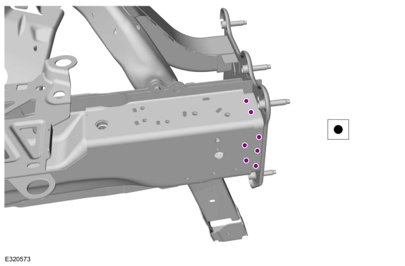
Carefully cut the outer panel only.
Use the General Equipment: Air Body Saw
Use the General Equipment: Spherical Cutter
.jpg) |
-
Remove the welds.
Use the General Equipment: Spot Weld Drill Bit
.jpg) |
-
Remove the welds.
Use the General Equipment: Spot Weld Drill Bit
.jpg) |
-
NOTE: Pay particular attention to the location of adhesives and sealers to aid in installation.
Remove the B-pillar outer panel.
Use the General Equipment: Hot Air Gun
.jpg) |
Installation
WARNING:
Electric vehicles damaged by a crash may have compromised
high voltage safety systems and present a potential high voltage
electrical shock hazard. Exercise caution and wear appropriate Personal
Protective Equipment (PPE) safety gear, including high voltage safety
gloves and boots. Remove all metallic jewelry, including watches and
rings. Isolate the HV system as directed by the Ford Emergency Response
Guide for the vehicle. Failure to follow these instructions may result
in serious personal injury or death.
NOTICE: Battery electric vehicle (BEV), hybrid electric vehicle (HEV) and plug-in hybrid electric vehicle (PHEV) contain a high-voltage battery. Before cutting or welding near the high-voltage battery it must be removed to avoid damage.
NOTICE: The high-voltage battery in a battery electric vehicle (BEV), hybrid electric vehicle (HEV) or plug-in hybrid electric vehicle (PHEV) can be affected and damaged by excessively high temperatures. The temperature in some body shop paint booths can exceed 60° C (140° F). Therefore, during refinishing operations, the paint booth temperature must set at or below 60° C (140° F) with a bake time of 45 minutes or less. Temperatures in excess of 60° C (140° F) or bake durations longer than 45 minutes will require the high-voltage battery be removed from the vehicle prior to placing in the paint booth.
NOTICE: If refinishing cure temperatures exceed 60° C (140° F), the charge port light ring on plug-in vehicles must be removed.
NOTE: Factory welds may be substituted with resistance or metal inert gas (MIG) plug welds. Resistance welds may not be placed directly over original location. They must be placed adjacent to original location and match factory welds in quantity. Metal inert gas (MIG) plug welds must equal factory welds in both location and quantity.
NOTE: Left hand (LH) side shown, right hand (RH) side similar.
-
Refer to: Health and Safety Precautions (100-00 General Information, Description and Operation).
WARNING:
Before beginning any service procedure in this
manual, refer to health and safety warnings in section 100-00 General
Information. Failure to follow this instruction may result in serious
personal injury.
Refer to: High Voltage System Health and Safety Precautions - Overview (100-00 General Information, Description and Operation).
-
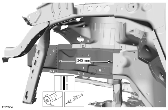
Carefully cut the body side service panel to fit the repair area.
Use the General Equipment: Air Body Saw
Use the General Equipment: Spherical Cutter
 |
-
Drill plug weld holes.
Use the General Equipment: 8 mm Drill Bit
.jpg) |
-
Sand to remove old adhesive or e-coat and clean.
.jpg) |
-
Apply adhesive.
Material: Metal Bonding Adhesive / TA-1, TA-1-B, 3M™ 08115, LORD Fusor® 108B, Henkel Teroson EP 5055
.jpg) |
-
Install, properly position and clamp the B-pillar outer panel section.
Use the General Equipment: Locking Pliers
.jpg) |
-
Install the welds.
Use the General Equipment: Resistance Spotwelding Equipment
.jpg) |
-
Install the welds.
Use the General Equipment: Resistance Spotwelding Equipment
.jpg) |
-
Install the welds.
Use the General Equipment: MIG/MAG Welding Equipment
.jpg) |
-
Completely seam weld the body section seams.
Use the General Equipment: MIG/MAG Welding Equipment
.jpg) |
-
Install NVH foam in areas noted during removal.
Material: Flexible Foam Repair / 3M™ 08463, LORD Fusor® 121
.jpg) |
-
Dress all welds as necessary using typical metal finishing techniques and materials.
-
Install the roof.
Refer to: Roof Panel (501-28 Roof Sheet Metal Repairs, Removal and Installation).
-
Refinish the entire repair using a Ford approved paint system.
-
Reposition the wiring harnesses and carpeting to original location.
-
Install the B-pillar trim panel.
Refer to: B-Pillar Trim Panel (501-05 Interior Trim and Ornamentation, Removal and Installation).
-
Install the front and rear door opening weather strips.
|
-
Install the front door striker and rear door hinges.
Torque:
1: 22 lb.ft (30 Nm)
2: 18 lb.ft (25 Nm)
 |
-
Install the rocker panel moulding.
Refer to: Rocker Panel Moulding (501-08 Exterior Trim and Ornamentation, Removal and Installation).
-
Install the rear door.
Refer to: Rear Door (501-03 Body Closures, Removal and Installation).
-
Install the front and rear door opening tread plates.
-
Align the doors.
Refer to: Rear Door Alignment (501-03 Body Closures, General Procedures).
Refer to: Front Door Alignment (501-03 Body Closures, General Procedures).
-
Restore corrosion protection.
Refer to: Corrosion Prevention (501-25 Body Repairs - General Information, General Procedures).
-
Repower the SRS .
Refer to: Supplemental Restraint System (SRS) Repowering (501-20B Supplemental Restraint System, General Procedures).

 Removal and Installation - Front Door Skin Panel
Special Tool(s) /
General Equipment
Scraper for Straight Edges
Grinder
Hot Air Gun
Knife
MIG/MAG Welding Equipment
Locking Pliers
Materials
Name
Specification
Metal Bonding AdhesiveTA-1, TA-1-B, 3M™ 08115, LORD Fusor® 108B, Henkel Teroson EP 5055
-
Seam SealerTA-2-B, 3M™ 08308, LORD Fusor® 803DTM
-
Flexible Foam Repair3Mâ..
Other information:
Ford Escape 2020-2026 Service Manual: Removal and Installation - Rear Seat Cushion Cover
Special Tool(s) / General Equipment Hog Ring Plier Removal NOTE: LH (left hand) shown, RH (right hand) similar. Remove the rear seat. Refer to: Rear Seat (501-10B Rear Seats, Removal and Installation). Release the retaining tabs and remove the lower child safety seat tether anchor bezels. Release the rear seat cushion substr..
Ford Escape 2020-2026 Owners Manual: Traction Control
How Does Traction Control Work If your vehicle begins to slide, the system applies the brakes to individual wheels and, when needed, reduces power at the same time. If the wheels spin when accelerating on slippery or loose surfaces, the system reduces power in order to increase traction. Switching Traction Control On and Off WARNING: The stability and traction control light illuminates stea..
Categories
- Manuals Home
- 4th Generation Ford Escape Owners Manual
- 4th Generation Ford Escape Service Manual
- Fuel Quality
- Removal and Installation - All-Wheel Drive (AWD) Module - 1.5L EcoBoost (132kW/180PS) – I3 (Y1)/2.0L EcoBoost (177kW/240PS) – MI4
- All-Wheel Drive
- New on site
- Most important about car
Symbols Glossary
These are some of the symbols you may see on your vehicle.
 Air conditioning system