Ford Escape: Multifunction Electronic Modules / Removal and Installation - Body Control Module (BCM)
Special Tool(s) / General Equipment
| Interior Trim Remover |
Removal
NOTE: Removal steps in this procedure may contain installation details.
-
If installing a new BCM , connect a battery charger to the battery to
make sure it is charged to maintain proper battery voltage.
Refer to: Battery Charging (414-01 Battery, Mounting and Cables, General Procedures).
-
NOTE: If the BCM (body control module) did not respond to the diagnostic scan tool, As-Built Data may need to be entered as part of the repair. This step is only necessary if the BCM (body control module) is being replaced.
Using a diagnostic scan tool, begin the PMI process for the BCM following the on-screen instructions.
Refer to: Module Configuration - System Operation and Component Description (418-01 Module Configuration, Description and Operation).
-
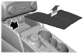
Remove the retainers and the lower insulation panel.
.jpg) |
-
Release the clips and remove the trim panel.
Use the General Equipment: Interior Trim Remover
.jpg) |
-
Disconnect the BCM electrical connectors.
.jpg) |
-
Release the clips and remove the BCM .
.jpg) |
Installation
-
To install, reverse the removal procedure.
NOTE: Carry out the remaining steps only if installing a new BCM .
-
NOTE: The PMI (programmable module installation) application in the scan tool will guide you through completing the BCM (body control module) programming and key programming.
Run the PMI on the BCM .
-
After keys have been programmed as directed by the on screen prompts,
and the BCM programming has fully completed (as indicated by a module
installation complete or successful message), carry out the PATS Module
Initialization using the FDRS Scan Tool PATS Application.
-
As directed by the scan tool, follow the onscreen promts to relearn the TPMS sensors.
Refer to: Tire Pressure Monitoring System (TPMS) Sensor Location Calibration (204-04B Tire Pressure Monitoring System (TPMS), General Procedures).
-
If equipped with a video rear parking aid (rear mounted only), using a
diagnostic scan tool, carry out the LIN New Module Initialization
function.
-
Using a diagnostic scan tool, carry out the BMS Learned Values Reset.
-
Configure the BCM Programmable Parameters.
Refer to: Module Programming (418-01 Module Configuration, General Procedures).
-
Using a diagnostic scan tool, carry out the BCM self-test (must include
an on-demand self-test) and then repeat the self-test to confirm all
DTC have been cleared.
-
NOTE: This step only applies to vehicles without a stand-alone PAM (parking assist control module).
Using a diagnostic scan tool, complete the PMI process for the PAM following the on-screen instructions.
Refer to: Module Configuration - System Operation and Component Description (418-01 Module Configuration, Description and Operation).
 General Procedures - Transport Mode Deactivation
Deactivation
NOTE:
After vehicle build, some vehicle modules are set in Transport mode
including the IPC and the BCM . Transport mode reduces battery drain
during longer periods where the vehicle is not used...
 Removal and Installation - Body Control Module C (BCMC)
Removal
NOTE:
Removal steps in this procedure may contain installation details.
NOTE:
If the BCMC (body control module C) did not respond
to the diagnostic scan tool, As-Built Data may need to be entered as
part of the repair...
Other information:
Ford Escape 2020-2026 Service Manual: Removal and Installation - High Voltage Battery Coolant Cooler
Special Tool(s) / General Equipment Hose Clamp(s) Hose Clamp Remover/Installer Removal NOTICE: During the removal of components, cap, tape or otherwise appropriately protect all openings to prevent the ingress of dirt or other contamination...
Ford Escape 2020-2026 Owners Manual: Brake Precautions. Anti-Lock Braking System. Brake Over Accelerator
Brake Precautions WARNING: Driving your vehicle with the warning lamp on is dangerous. A significant decrease in braking performance may occur. It may take you longer to stop your vehicle. Have your vehicle checked as soon as possible. Driving extended distances with the parking brake engaged can cause brake failure and the risk of personal injury...
Categories
- Manuals Home
- 4th Generation Ford Escape Owners Manual
- 4th Generation Ford Escape Service Manual
- Locating the Pre-Collision Assist Sensors
- Child Safety Locks
- All-Wheel Drive
- New on site
- Most important about car
Master Access Code
What Is the Master Access Code
The master access code is a factory-set five-digit entry code. You can operate the keypad with the master access code at any time. The master access code is on the owner’s wallet card in the glove box and is available from an authorized dealer.
Displaying the Master Access Code
To display the factory-set code in the information display:

