Ford Escape: Engine / Removal and Installation - Camshafts
Special Tool(s) / General Equipment
 |
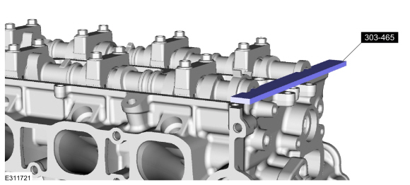
303-465 Tool, Camshaft Align Timing TKIT-1994-LMH/MH2 TKIT-1994-FH/FMH/FLMH |
 |
303-507 Timing Peg, Crankshaft TDC TKIT-2001N-FLM TKIT-2001N-ROW |
| Feeler Gauge | |
Removal
NOTE: During engine repair procedures, cleanliness is extremely important. Any foreign material (including any material created while cleaning gasket surfaces) that enters the oil passages, coolant passages or the oil pan can cause engine failure.
NOTE: Do not rotate the camshafts unless instructed to in this procedure. Rotating the camshafts or crankshaft with timing components loosened or removed can cause serious damage to the valves and pistons.
-
Remove the VCT unit.
Refer to: Variable Camshaft Timing (VCT) Unit (303-01C Engine, Removal and Installation).
-
Remove the bolt and the VCT oil control solenoid.
.jpg) |
- Remove Special Service Tool: 303-465 Tool, Camshaft Align Timing.
 |
-
NOTE: Failure to follow the camshaft loosening procedure can result in damage to the camshafts.
NOTE: Mark the location and orientation of each camshaft bearing cap.
NOTE: Mark the location of the camshafts prior to removal.
Loosen the camshaft bearing cap bolts in sequence one turn at a time until all tension is released from the camshaft bearing caps. Remove the bolts and the camshaft bearing caps.
.jpg) |
-
Remove the camshafts.
.jpg) |
Installation
-
NOTE: If any new parts are being installed (cylinder head, valves, tappets, camshafts) it is necessary to check the valve clearance, follow the next 10 steps exactly or serious damage to the engine may occur. If the original parts are being installed it is not necessary to check the valve clearance so proceed to step 11.
Place a paint mark on the crankshaft at the 12 o'clock position.
.jpg) |
- Remove Special Service Tool: 303-507 Timing Peg, Crankshaft TDC.
.jpg) |
-
NOTE: Rotating the crankshaft will position all of the pistons below the deck of the cylinder block and allow the camshafts to be installed and the valve clearance checked without the possibility of damage to the valves or pistons.
Using the crankshaft bolt and washer, rotate the crankshaft clockwise 270 degrees until the paint mark is at the 9 o'clock position.
.jpg) |
-
NOTE: Component(s) must be lubricated with clean engine oil.
Lubricate the camshafts with clean engine oil and install.
Refer to: Specifications (303-01C Engine, Specifications).
.jpg) |
-
NOTE: Failure to follow the camshaft tightening procedure can result in damage to the camshafts.
NOTE: Lubricate the camshaft journals and camshaft bearing caps with clean engine oil.
-
Lubricate the camshaft bearing caps with clean engine oil and install the camshaft bearing caps and bolts.
Refer to: Specifications (303-01C Engine, Specifications).
-
Tighten the camshaft bearing cap bolts one turn at a time, until finger-tight.
-
Tighten the camshaft bearing cap bolts in sequence shown in 2 stages.
Torque:
Stage 1: 62 lb.in (7 Nm)
Stage 2: 142 lb.in (16 Nm)
-
Lubricate the camshaft bearing caps with clean engine oil and install the camshaft bearing caps and bolts.
.jpg) |
-
-
Using the flats of the camshaft, rotate the camshaft
to place the cam lobe at base circle, with the lobe pointed away from
the tappet.
-
Use a feeler gauge to measure the clearance of each valve and record its location.
Use the General Equipment: Feeler Gauge
-
Repeat to measure all of the lobe/tappet clearances.
-
Using the flats of the camshaft, rotate the camshaft
to place the cam lobe at base circle, with the lobe pointed away from
the tappet.
.jpg) |
-
NOTE: The number on the valve tappet only reflects the digits that follow the decimal. For example, a tappet with the number 0.650 has the thickness of 3.650 mm.
NOTE: Select tappets using this formula: ideal tappet thickness = measured clearance + the existing tappet thickness - nominal clearance.
NOTE: The nominal clearance is:
- intake: 0.25 mm (0.0098 in).
- exhaust: 0.30 mm (0.0118 in).
NOTE: The acceptable clearances after being fully installed are:
- intake: 0.23-0.28 mm (0.009-0.011 in).
- exhaust: 0.27-0.33 mm (0.010-0.013 in).
-
NOTE: Failure to follow the camshaft loosening procedure can result in damage to the camshafts.
NOTE: Mark the location and orientation of each camshaft bearing cap.
NOTE: Mark the location of the camshafts prior to removal.
Loosen the camshaft bearing cap bolts in sequence one turn at a time until all tension is released from the camshaft bearing caps. Remove the bolts and the camshaft bearing caps.
|
-
Remove the camshafts.
|
- Install Special Service Tool: 303-507 Timing Peg, Crankshaft TDC.
|
-
NOTE: Rotating the crankshaft will position the engine at TDC and allow you to install the camshafts in the same position as noted during the disassembly.
Rotate the crankshaft clockwise 90 degrees so the crankshaft contacts the TDC timing peg.
Install Special Service Tool: 303-507 Timing Peg, Crankshaft TDC.
.jpg) |
-
NOTE: Component(s) must be lubricated with clean engine oil.
If necessary, lubricate with clean engine oil and replace any tappets with the correct tappets selected during the valve clearance check.
Refer to: Specifications (303-01C Engine, Specifications).
.jpg) |
-
NOTE: Install the camshafts with the alignment slots in the camshafts lined up so the Camshaft Alignment Plate can be installed without rotating the camshafts. Make sure the lobes on the No. 1 cylinder are in the same position as noted in the removal procedure. Rotating the camshafts when the timing chain is removed, or installing the camshafts 180 degrees out of position can cause severe damage to the valves and pistons.
NOTE: Component(s) must be lubricated with clean engine oil.
Lubricate the camshafts and the camshaft journals with clean engine oil and install the camshafts.
Refer to: Specifications (303-01C Engine, Specifications).
.jpg) |
-
NOTE: Failure to follow the camshaft tightening procedure can result in damage to the camshafts.
NOTE: Lubricate the camshaft journals and camshaft bearing caps with clean engine oil.
-
Lubricate the camshaft bearing caps with clean engine oil and install the camshaft bearing caps and bolts.
Refer to: Specifications (303-01C Engine, Specifications).
-
Tighten the camshaft bearing cap bolts one turn at a time, until finger-tight.
-
Tighten the camshaft bearing cap bolts in sequence shown in 2 stages.
Torque:
Stage 1: 62 lb.in (7 Nm)
Stage 2: 142 lb.in (16 Nm)
-
Lubricate the camshaft bearing caps with clean engine oil and install the camshaft bearing caps and bolts.
|
-
NOTE: The Camshaft Alignment Tool is for camshaft alignment only. Using this tool to prevent engine rotation can result in engine damage.
Install Special Service Tool: 303-465 Tool, Camshaft Align Timing.
|
-
Install the VCT oil control solenoid and the bolt.
Torque: 97 lb.in (11 Nm)
|
-
Install the VCT unit.
Refer to: Variable Camshaft Timing (VCT) Unit (303-01C Engine, Removal and Installation).
-
Road test the vehicle.
 General Procedures - Engine Oil Draining and Filling
Special Tool(s) /
General Equipment
Oil Drain Equipment
Draining
With the vehicle in NEUTRAL, position it on a hoist.
Refer to: Jacking and Lifting - Overview (100-02 Jacking and Lifting, Description and Operation)...
 Removal and Installation - Crankshaft Front Seal
Special Tool(s) /
General Equipment
303-096
(T74P-6150-A)
Installer, Camshaft Front Oil SealTKIT-2009TC-F
303-409
(T92C-6700-CH)
Remover, Crankshaft SealTKIT-1992-FH/FMH/FLMHTKIT-1993-LMH/MH
303-507Timing Peg, Crankshaft TDCTKIT-2001N-FLMTKIT-2001N-ROW
Removal
Remove the crankshaft pulley...
Other information:
Ford Escape 2020-2026 Service Manual: Diagnosis and Testing - Autolamps
Diagnostic Trouble Code (DTC) Chart Diagnostics in this manual assume a certain skill level and knowledge of Ford-specific diagnostic practices. REFER to: Diagnostic Methods (100-00 General Information, Description and Operation). Diagnostic Trouble Code Chart Module DTC Description Action BCM B1A85..
Ford Escape 2020-2026 Service Manual: General Procedures - Door Latch Lubrication
Special Tool(s) / General Equipment Flat-Bladed Screwdriver Materials Name Specification Motorcraft® Multi-Purpose Grease SprayXL-5-A ESB-M1C93-B Activation NOTE: Typical left front door shown, others similar. Open the door. Using a flat blade screwdriver, fully close the latch (2 clicks). Use the General Equipment: Fla..
Categories
- Manuals Home
- 4th Generation Ford Escape Owners Manual
- 4th Generation Ford Escape Service Manual
- Adjusting the Headlamps
- General Procedures - Brake Service Mode Activation and Deactivation
- Symbols Glossary
- New on site
- Most important about car
Under Hood Fuse Box
Locating the Under Hood Fuse Box

Accessing the Under Hood Fuse Box
