Ford Escape: Front End Sheet Metal Repairs / Removal and Installation - Dash Panel
Special Tool(s) / General Equipment
| 8 mm Drill Bit | |
| MIG/MAG Welding Equipment | |
| Spot Weld Drill Bit | |
| Locking Pliers |
Materials
| Name | Specification |
|---|---|
| Seam Sealer TA-2-B, 3M™ 08308, LORD Fusor® 803DTM |
- |
Removal
NOTICE: Battery electric vehicle (BEV), hybrid electric vehicle (HEV) and plug-in hybrid electric vehicle (PHEV) contain a high-voltage battery. Before cutting or welding near the high-voltage battery it must be removed to avoid damage.
NOTE: Roof removed for clarity.
NOTE: Factory welds may be substituted with resistance or metal inert gas (MIG) plug welds. Resistance welds may not be placed directly over original location. They must be placed adjacent to original location and match factory welds in quantity. Metal inert gas (MIG) plug welds must equal factory welds in both location and quantity.
NOTE: Adequately protect all adjacent areas against cutting, grinding and welding procedures.
-
Depower the SRS .
Refer to: Supplemental Restraint System (SRS) Depowering (501-20B Supplemental Restraint System, General Procedures).
-
Remove the windshield glass.
Refer to: Fixed Glass (501-11 Glass, Frames and Mechanisms, General Procedures).
-
If Required:
Dimensionally restore the vehicle to pre-damage condition.
Refer to: Body and Frame (501-26 Body Repairs - Vehicle Specific Information and Tolerance Checks, Description and Operation).
-
On Both Sides:
Remove the front seat and seat track.
Refer to: Front Seat (501-10A Front Seats, Removal and Installation).
Refer to: Front Seat Track (501-10A Front Seats, Removal and Installation).
-
Remove the instrument panel.
Refer to: Instrument Panel (501-12 Instrument Panel and Console, Removal and Installation).
-
Remove the climate control housing.
Refer to: Climate Control Housing (412-00 Climate Control System - General Information, Removal and Installation).
-
Position the carpet, all modules and wiring harnesses away from the working area.
-
Remove the hood.
Refer to: Hood (501-02 Front End Body Panels, Removal and Installation).
-
On Both Sides:
Remove the fender.
Refer to: Fender (501-02 Front End Body Panels, Removal and Installation).
Refer to: Fender - Plug-In Hybrid Electric Vehicle (PHEV) (501-02 Front End Body Panels, Removal and Installation).
-
Remove the front bumper.
Refer to: Front Bumper (501-19 Bumpers, Removal and Installation).
-
Remove the engine.
Refer to: Engine (303-01A Engine - 1.5L EcoBoost (132kW/180PS) – I3 (Y1), Removal).
Refer to: Engine (303-01B Engine - 2.0L EcoBoost (177kW/240PS) – MI4, Removal).
Refer to: Engine (303-01C Engine, Removal).
Refer to: Engine (303-01C Engine, Removal).
-
Remove the front subframe.
Refer to: Front Subframe (502-00 Uni-Body, Subframe and Mounting System, Removal and Installation).
-
Remove the brake master cylinder and brake pedal and bracket.
Refer to: Brake Master Cylinder - Vehicles With: Vacuum Brake Booster (206-06 Hydraulic Brake Actuation, Removal and Installation).
Refer to: Brake Pedal and Bracket - Vehicles With: Vacuum Brake Booster (206-06 Hydraulic Brake Actuation, Removal and Installation).
Refer to: Brake Pedal and Bracket - Vehicles With: Electric Brake Booster (206-06 Hydraulic Brake Actuation, Removal and Installation).
-
Remove the wiper linkage assembly.
Refer to: Wiper Linkage Assembly (501-16 Wipers and Washers, Removal and Installation).
-
Remove the cowl panel.
-
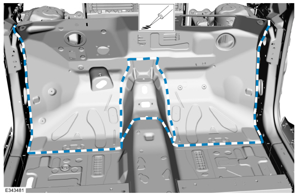
NOTE: Use care during removal, the reinforcement is part of the front floor panel and will be reused.
NOTE: Left hand (LH) side shown, right hand (RH) side similar.
Remove the welds and the front floor pan reinforcement.
Use the General Equipment: Spot Weld Drill Bit
.jpg) |
-
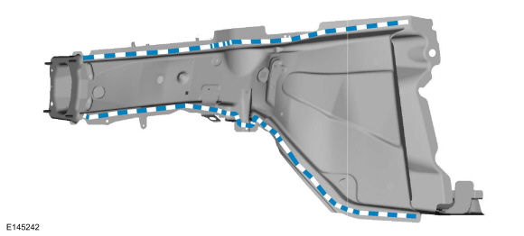
NOTE: Right hand (RH) side shown, left hand (LH) side similar.
On both sides:
Remove the welds and the dash panel reinforcement.
Use the General Equipment: Spot Weld Drill Bit
.jpg) |
-
Remove the welds and the lower dash panel reinforcement.
Use the General Equipment: Spot Weld Drill Bit
.jpg) |
-
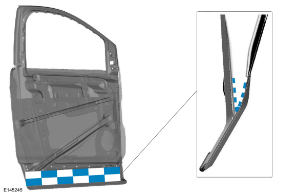
NOTE: Left hand (LH) side shown, right hand (RH) side similar.
On Both Sides:
Remove the welds.
Use the General Equipment: Spot Weld Drill Bit
.jpg) |
-
NOTE: Pay particular attention to the location of noise, vibration and harshness (NVH) material, adhesive and sealer used to aid in installation.
Remove the dash panel.
.jpg) |
Installation
NOTICE: Battery electric vehicle (BEV), hybrid electric vehicle (HEV) and plug-in hybrid electric vehicle (PHEV) contain a high-voltage battery. Before cutting or welding near the high-voltage battery it must be removed to avoid damage.
NOTICE: The high-voltage battery in a battery electric vehicle (BEV), hybrid electric vehicle (HEV) or plug-in hybrid electric vehicle (PHEV) can be affected and damaged by excessively high temperatures. The temperature in some body shop paint booths can exceed 60° C (140° F). Therefore, during refinishing operations, the paint booth temperature must set at or below 60° C (140° F) with a bake time of 45 minutes or less. Temperatures in excess of 60° C (140° F) or bake durations longer than 45 minutes will require the high-voltage battery be removed from the vehicle prior to placing in the paint booth.
NOTICE: If refinishing cure temperatures exceed 60° C (140° F), the charge port light ring on plug-in vehicles must be removed.
NOTE: Roof removed for clarity.
NOTE: Factory welds may be substituted with resistance or metal inert gas (MIG) plug welds. Resistance welds may not be placed directly over original location. They must be placed adjacent to original location and match factory welds in quantity. Metal inert gas (MIG) plug welds must equal factory welds in both location and quantity.
NOTE: Adequately protect all adjacent areas against cutting, grinding and welding procedures.
-
NOTE: Left hand (LH) side shown, right hand (RH) side similar.
Drill plug weld holes in the replacement dash panel.
Use the General Equipment: 8 mm Drill Bit
 |
-
Install, properly position and clamp the replacement dash panel.
Use the General Equipment: Locking Pliers
.jpg) |
-
NOTE: Left hand (LH) side shown, right hand (RH) side similar.
On Both Sides:
Install the welds.
Use the General Equipment: MIG/MAG Welding Equipment
.jpg) |
-
Drill plug weld holes in the replacement lower dash panel reinforcement.
Use the General Equipment: 8 mm Drill Bit
.jpg) |
-
Install, properly position, clamp and weld the lower dash panel reinforcement.
Use the General Equipment: MIG/MAG Welding Equipment
Use the General Equipment: Locking Pliers
.jpg) |
-
Seam Sealing:
All seams must be sealed to production level.
Material: Seam Sealer / TA-2-B, 3M™ 08308, LORD Fusor® 803DTM
 |
-
NOTE: Right hand (RH) side shown, left hand (LH) side similar.
On both sides:
Drill plug weld holes in the replacement dash panel rienforcement.
Use the General Equipment: 8 mm Drill Bit
.jpg) |
-
NOTE: Right hand (RH) side shown, left hand (LH) side similar.
On Both Sides:
Install, properly position, clamp and weld the reinforcement.
Use the General Equipment: MIG/MAG Welding Equipment
Use the General Equipment: Locking Pliers
.jpg) |
-
Dress all welds as required using typical metal finishing techniques and materials.
-
Install the front floor pan reinforcement, properly position, clamp and install the welds.
Use the General Equipment: Locking Pliers
Use the General Equipment: MIG/MAG Welding Equipment
.jpg) |
-
Seam Sealing:
All seams must be sealed to production level.
Material: Seam Sealer / TA-2-B, 3M™ 08308, LORD Fusor® 803DTM
 |
-
Install the cowl panel.
-
Sand to remove old adhesive, paint, e-coat and clean.
.jpg) |
-
Apply a Ford approved epoxy-based primer and allow to dry.
.jpg) |
-
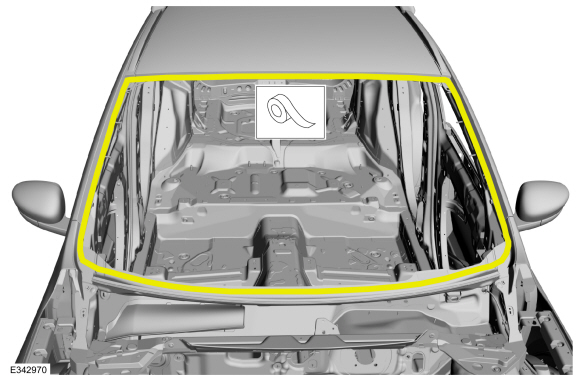
Mask the windshield channel.
.jpg) |
-
Refinish the entire repair using a Ford approved paint system.
-
Remove the masking material from the windshield channel.
 |
-
Obtain and install a new VIN plate.
Refer to: Identification Codes (100-01 Identification Codes, Description and Operation).
-
Install the windshield glass.
Refer to: Fixed Glass (501-11 Glass, Frames and Mechanisms, General Procedures).
-
Restore corrosion protection.
Refer to: Corrosion Prevention (501-25 Body Repairs - General Information, General Procedures).
-
Reposition all wiring harnesses, modules and the carpet to original locations.
-
Install the engine.
Refer to: Engine (303-01A Engine - 1.5L EcoBoost (132kW/180PS) – I3 (Y1), Installation).
Refer to: Engine (303-01B Engine - 2.0L EcoBoost (177kW/240PS) – MI4, Installation).
Refer to: Engine (303-01C Engine, Installation).
Refer to: Engine (303-01C Engine, Installation).
-
Install the brake master cylinder and brake pedal and bracket.
Refer to: Brake Master Cylinder - Vehicles With: Vacuum Brake Booster (206-06 Hydraulic Brake Actuation, Removal and Installation).
Refer to: Brake Pedal and Bracket - Vehicles With: Vacuum Brake Booster (206-06 Hydraulic Brake Actuation, Removal and Installation).
Refer to: Brake Pedal and Bracket - Vehicles With: Electric Brake Booster (206-06 Hydraulic Brake Actuation, Removal and Installation).
-
Install the front subframe.
Refer to: Front Subframe (502-00 Uni-Body, Subframe and Mounting System, Removal and Installation).
-
Install the wiper linkage assembly.
Refer to: Wiper Linkage Assembly (501-16 Wipers and Washers, Removal and Installation).
-
Install the climate control housing.
Refer to: Climate Control Housing (412-00 Climate Control System - General Information, Removal and Installation).
-
Install the instrument panel.
Refer to: Instrument Panel (501-12 Instrument Panel and Console, Removal and Installation).
-
On Both Sides:
Install the front seat track and front seat.
Refer to: Front Seat Track (501-10A Front Seats, Removal and Installation).
Refer to: Front Seat (501-10A Front Seats, Removal and Installation).
-
On Both Sides:
Install the fender.
Refer to: Fender (501-02 Front End Body Panels, Removal and Installation).
Refer to: Fender - Plug-In Hybrid Electric Vehicle (PHEV) (501-02 Front End Body Panels, Removal and Installation).
-
Install the front bumper.
Refer to: Front Bumper (501-19 Bumpers, Removal and Installation).
-
Install and align the hood.
Refer to: Hood (501-02 Front End Body Panels, Removal and Installation).
Refer to: Hood Alignment (501-03 Body Closures, General Procedures).
-
Repower the SRS .
Refer to: Supplemental Restraint System (SRS) Repowering (501-20B Supplemental Restraint System, General Procedures).

 Removal and Installation - Fender Apron Panel
Special Tool(s) /
General Equipment
Resistance Spotwelding Equipment
Spherical Cutter
Grinder
Air Body Saw
8 mm Drill Bit
MIG/MAG Welding Equipment
Spot Weld Drill Bit
Locking Pliers
Removal
WARNING:
Electric vehicles damaged by a crash may have compromised
high voltage safety systems and present a potential high voltage
electrical shock ..
Other information:
Ford Escape 2020-2026 Service Manual: Removal and Installation - Cowl Panel Grille
Removal NOTE: Removal steps in this procedure may contain installation details. Remove the windshield wiper pivot arm. Refer to: Windshield Wiper Pivot Arm (501-16 Wipers and Washers, Removal and Installation). Remove the clips. Pull outward to release the locking clips and position the upper portion of the cowl panel grille away fro..
Ford Escape 2020-2026 Owners Manual: Resetting the Individual Trip Values, Configuring the Trip Computer - Vehicles With: 4.2 Inch Instrument Cluster Display Screen. Trip Data
Resetting the Individual Trip Values Use the instrument cluster display controls to navigate the home screen. Select the trip screen. Press the menu button on the steering wheel. Select Reset Individual Values. Select a trip value to reset. Press and hold the OK button until the system reset confirmation appears. Configuring the Trip Computer Use the instrument cluster display co..
Categories
- Manuals Home
- 4th Generation Ford Escape Owners Manual
- 4th Generation Ford Escape Service Manual
- Switching the Lane Keeping System On and Off. Switching the Lane Keeping System Mode. Alert Mode
- General Procedures - Brake Service Mode Activation and Deactivation
- Fuel Quality
- New on site
- Most important about car
Master Access Code
What Is the Master Access Code
The master access code is a factory-set five-digit entry code. You can operate the keypad with the master access code at any time. The master access code is on the owner’s wallet card in the glove box and is available from an authorized dealer.
Displaying the Master Access Code
To display the factory-set code in the information display:
