Ford Escape: Front End Sheet Metal Repairs / Removal and Installation - Fender Apron Panel
Special Tool(s) /
General Equipment
| Resistance Spotwelding Equipment |
| Spherical Cutter |
| Grinder |
| Air Body Saw |
| 8 mm Drill Bit |
| MIG/MAG Welding Equipment |
| Spot Weld Drill Bit |
| Locking Pliers |
Removal
.jpg) WARNING:
Electric vehicles damaged by a crash may have compromised
high voltage safety systems and present a potential high voltage
electrical shock hazard. Exercise caution and wear appropriate Personal
Protective Equipment (PPE) safety gear, including high voltage safety
gloves and boots. Remove all metallic jewelry, including watches and
rings. Isolate the HV system as directed by the Ford Emergency Response
Guide for the vehicle. Failure to follow these instructions may result
in serious personal injury or death.
WARNING:
Electric vehicles damaged by a crash may have compromised
high voltage safety systems and present a potential high voltage
electrical shock hazard. Exercise caution and wear appropriate Personal
Protective Equipment (PPE) safety gear, including high voltage safety
gloves and boots. Remove all metallic jewelry, including watches and
rings. Isolate the HV system as directed by the Ford Emergency Response
Guide for the vehicle. Failure to follow these instructions may result
in serious personal injury or death.
NOTICE:
Battery electric vehicle (BEV), hybrid electric vehicle
(HEV) and plug-in hybrid electric vehicle (PHEV) contain a high-voltage
battery. Before cutting or welding near the high-voltage battery it must
be removed to avoid damage.
NOTE:
Left hand (LH) side shown, right hand (RH) side similar.
-
WARNING:
Before beginning any service procedure in this
manual, refer to health and safety warnings in section 100-00 General
Information. Failure to follow this instruction may result in serious
personal injury.
Refer to: Health and Safety Precautions (100-00 General Information, Description and Operation).
Refer to: High Voltage System Health and Safety Precautions - Overview (100-00 General Information, Description and Operation).
-
Remove the headlamp assembly.
Refer to: Headlamp Assembly (417-01 Exterior Lighting, Removal and Installation).
-
Removed the hood, fender and fender splash shield.
Refer to: Hood (501-02 Front End Body Panels, Removal and Installation).
Refer to: Fender Splash Shield (501-02 Front End Body Panels, Removal and Installation).
Refer to: Fender (501-02 Front End Body Panels, Removal and Installation).
-
Remove the front bumper.
Refer to: Front Bumper (501-19 Bumpers, Removal and Installation).
-
Remove the engine cooling module.
Refer to: Cooling Module (303-03B Engine Cooling - 2.0L EcoBoost (177kW/240PS) – MI4, Removal and Installation).
Refer to: Cooling Module (303-03B Engine Cooling - 2.0L EcoBoost (177kW/240PS) – MI4, Removal and Installation).
Refer to: Cooling Module (303-03C Engine Cooling, Removal and Installation).
-
Remove the bolts and lower radiator support.
-
Remove the bolts and the brace.
-
If Necessary:
Dimensionally restore the vehicle to pre-damage condition.
Refer to: Body and Frame (501-26 Body Repairs - Vehicle Specific Information and Tolerance Checks, Description and Operation).
-
Remove the welds.
Use the General Equipment: Spot Weld Drill Bit
-
Remove the welds.
Use the General Equipment: Spot Weld Drill Bit
-
Remove the bumper bracket.
-
Remove the welds and the upper fender bracket.
-
Remove the bolts.
-
Remove the bolts.
-
Remove the bolt.
-
Remove the welds and the fender apron tube brace.
Use the General Equipment: Spot Weld Drill Bit
Use the General Equipment: Spherical Cutter
-
Remove the welds.
Use the General Equipment: Spot Weld Drill Bit
-
Remove the welds.
Use the General Equipment: Spot Weld Drill Bit
-
Remove the welds.
Use the General Equipment: Spot Weld Drill Bit
-
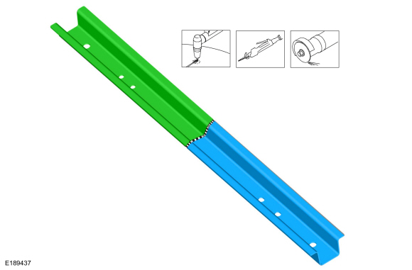
NOTICE:
Use care to cut the apron tube only.
Carefully cut and remove the fender apron tube as shown.
Use the General Equipment: Air Body Saw
Use the General Equipment: Spherical Cutter
-
Remove the welds and the remaining portion of the fender apron tube.
Use the General Equipment: Spherical Cutter
Installation
WARNING:
Electric vehicles damaged by a crash may have compromised
high voltage safety systems and present a potential high voltage
electrical shock hazard. Exercise caution and wear appropriate Personal
Protective Equipment (PPE) safety gear, including high voltage safety
gloves and boots. Remove all metallic jewelry, including watches and
rings. Isolate the HV system as directed by the Ford Emergency Response
Guide for the vehicle. Failure to follow these instructions may result
in serious personal injury or death.
NOTICE:
Battery electric vehicle (BEV), hybrid electric vehicle
(HEV) and plug-in hybrid electric vehicle (PHEV) contain a high-voltage
battery. Before cutting or welding near the high-voltage battery it must
be removed to avoid damage.
NOTICE:
The high-voltage battery in a battery electric vehicle
(BEV), hybrid electric vehicle (HEV) or plug-in hybrid electric vehicle
(PHEV) can be affected and damaged by excessively high temperatures. The
temperature in some body shop paint booths can exceed 60° C (140° F).
Therefore, during refinishing operations, the paint booth temperature
must set at or below 60° C (140° F) with a bake time of 45 minutes or
less. Temperatures in excess of 60° C (140° F) or bake durations longer
than 45 minutes will require the high-voltage battery be removed from
the vehicle prior to placing in the paint booth.
NOTICE:
If refinishing cure temperatures exceed 60° C (140° F), the
charge port light ring on plug-in vehicles must be removed.
NOTE:
Factory welds may be substituted with resistance or metal
inert gas (MIG) plug welds. Resistance welds may not be placed directly
over original location. They must be placed adjacent to original
location and match factory welds in quantity. Metal inert gas (MIG) plug
welds must equal factory welds in both location and quantity.
NOTE:
Left hand (LH) side shown, right hand (RH) side similar.
-
WARNING:
Before beginning any service procedure in this
manual, refer to health and safety warnings in section 100-00 General
Information. Failure to follow this instruction may result in serious
personal injury.
Refer to: Health and Safety Precautions (100-00 General Information, Description and Operation).
Refer to: High Voltage System Health and Safety Precautions - Overview (100-00 General Information, Description and Operation).
-
Drill plug weld holes.
Use the General Equipment: 8 mm Drill Bit
-
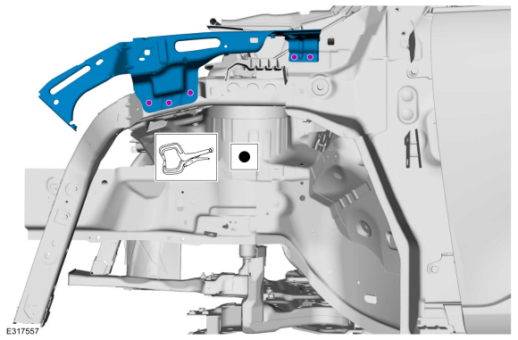
Install, properly position and clamp the fender apron tube.
Use the General Equipment: Locking Pliers
-
Install the bolts.
Torque:
18 lb.ft (25 Nm)
-
Install the bolts.
Torque:
18 lb.ft (25 Nm)
-
Install the bolt.
Torque:
35 lb.ft (47 Nm)
-
Install the welds.
Use the General Equipment: MIG/MAG Welding Equipment
-
Install the welds.
Use the General Equipment: Resistance Spotwelding Equipment
-
Install the welds.
Use the General Equipment: Resistance Spotwelding Equipment
-
Drill plug weld holes.
Use the General Equipment: 8 mm Drill Bit
-
Install, properly position and clamp the fender apron tube brace.
Use the General Equipment: Locking Pliers
-
Install the welds.
Use the General Equipment: Resistance Spotwelding Equipment
-
Install the welds.
Use the General Equipment: MIG/MAG Welding Equipment
-
Install, properly position and clamp the bumper bracket.
Use the General Equipment: Locking Pliers
-
Install the welds.
Use the General Equipment: Resistance Spotwelding Equipment
-
Install the welds.
Use the General Equipment: Resistance Spotwelding Equipment
-
Install the upper fender bracket and welds.
Use the General Equipment: Locking Pliers
Use the General Equipment: Resistance Spotwelding Equipment
-
Install the brace and bolts.
Torque:
22 lb.ft (30 Nm)
-
Install the lower radiator support and bolts.
Torque:
22 lb.ft (30 Nm)
-
Metal finish all welds as necessary.
Use the General Equipment: Grinder
-
Refinish the entire repair using a Ford approved paint system.
-
Restore corrosion protection.
Refer to: Corrosion Prevention (501-25 Body Repairs - General Information, General Procedures).
-
Install the engine cooling module.
Refer to: Cooling Module (303-03B Engine Cooling - 2.0L EcoBoost (177kW/240PS) – MI4, Removal and Installation).
Refer to: Cooling Module (303-03B Engine Cooling - 2.0L EcoBoost (177kW/240PS) – MI4, Removal and Installation).
Refer to: Cooling Module (303-03C Engine Cooling, Removal and Installation).
-
Install the hood, fender and fender splash shield.
Refer to: Hood (501-02 Front End Body Panels, Removal and Installation).
Refer to: Fender (501-02 Front End Body Panels, Removal and Installation).
Refer to: Fender Splash Shield (501-02 Front End Body Panels, Removal and Installation).
-
Install the headlamp assembly.
Refer to: Headlamp Assembly (417-01 Exterior Lighting, Removal and Installation).
-
Install the front bumper and cover.
Refer to: Front Bumper (501-19 Bumpers, Removal and Installation).
Refer to: Front Bumper Cover (501-19 Bumpers, Disassembly and Assembly).
Special Tool(s) /
General Equipment
Resistance Spotwelding Equipment
8 mm Drill Bit
MIG/MAG Welding Equipment
Spot Weld Drill Bit
Locking Pliers
Materials
Name
Specification
Metal Bonding AdhesiveTA-1, TA-1-B, 3M™ 08115, LORD Fusor® 108B, Henkel Teroson EP 5055
-
Removal
WARNING:
Electric vehicles damaged by a crash may have compr..
Other information:
Removal
NOTE:
This procedure is for the roof opening panel sliding glass only.
Open the roof opening panel glass slightly to gain access to the roof opening panel glass screws.
If closed, open the roof opening panel shield.
Remove the RH roof opening panel glass screws.
Remove the LH roo..
Removal
NOTE:
Removal steps in this procedure may contain installation details.
Remove the intake manifold.
Refer to: Intake Manifold (303-01C Engine, Removal and Installation).
Remove the bolt and the KS .
Torque:
177 lb.in (20 Nm)
Installation
To install, reverse the removal procedure.
..
.jpg)
.jpg)
.jpg)
.jpg)
.jpg)
.jpg)
.jpg)
.jpg)
.jpg)
.jpg)
.jpg)
.jpg)
.jpg)
.jpg)
.jpg)
.jpg)
.jpg)
.jpg)
.jpg)
.jpg)
.jpg)
.jpg)
.jpg)
.jpg)
.jpg)
.jpg)

 Removal and Installation - Fender Apron Panel Reinforcement