Ford Escape: Engine / Removal and Installation - Engine Front Cover
Special Tool(s) / General Equipment
| Plastic Scraper | |
| Trolley Jack |
Materials
| Name | Specification |
|---|---|
| Motorcraft® High Performance Engine RTV Silicone TA-357 |
WSE-M4G323-A6 |
| Motorcraft® Silicone Gasket Remover ZC-30-A, AZC-30-C |
- |
| Motorcraft® Metal Surface Prep Wipes ZC-31-B |
- |
| Motorcraft® Metal Brake Parts Cleaner PM-4-A, PM-4-B, APM-4-C |
- |
Removal
NOTICE: Do not loosen or remove the crankshaft pulley bolt without first installing the special tools as instructed in this procedure. The crankshaft pulley and the crankshaft timing sprocket are not keyed to the crankshaft. The crankshaft, the crankshaft sprocket and the pulley are fitted together by friction. For that reason, the crankshaft sprocket is also unfastened if the pulley bolt is loosened. Before any repair requiring loosening or removal of the crankshaft pulley bolt, the crankshaft and camshafts must be locked in place by the special service tools, otherwise severe engine damage can occur.
NOTICE: During engine repair procedures, cleanliness is extremely important. All parts must be thoroughly cleaned and any foreign material, including any material created while cleaning gasket surfaces, that enters the oil passages, coolant passages or the oil pan, can cause engine failure.
-
Drain the cooling system.
Refer to: Engine Cooling System Draining, Vacuum Filling and Bleeding (303-03C Engine Cooling, General Procedures).
-
Remove the A/C compressor inlet line.
Refer to: Air Conditioning (A/C) Compressor Inlet Line - 2.5L Duratec – Hybrid (121kW/164PS) (BG) (412-00 Climate Control System - General Information, Removal and Installation).
-
Remove the crankshaft front seal.
Refer to: Crankshaft Front Seal (303-01C Engine, Removal and Installation).
-
Remove the engine mount.
Refer to: Engine Mount (303-01C Engine, Removal and Installation).
-
Raise the engine 88.9 mm ( 3.5 inches ).
Use the General Equipment: Trolley Jack
 |
-
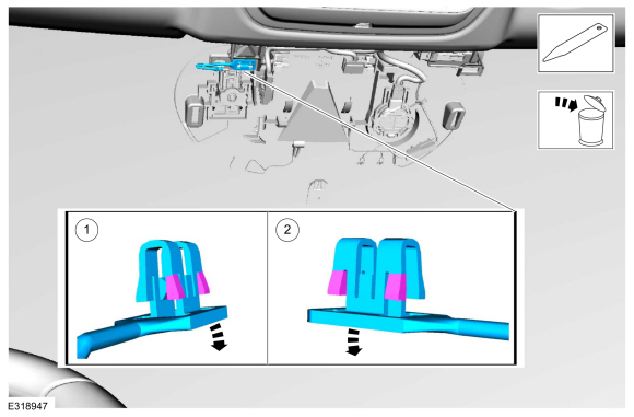
Disconnect the hose, remove the bolts and the coolant outlet assembly.
.jpg) |
-
Remove the engine mount studs.
.jpg) |
-
Remove the bolts and the engine front cover.
 |
Installation
-
NOTE: Make sure that the mating faces are clean and free of foreign material.
Refer to: RTV Sealing Surface Cleaning and Preparation (303-00 Engine System - General Information, General Procedures).
Use the General Equipment: Plastic Scraper
Material: Motorcraft® Silicone Gasket Remover / ZC-30-A, AZC-30-C
Material: Motorcraft® Metal Brake Parts Cleaner / PM-4-A, PM-4-B, APM-4-C
Material: Motorcraft® Metal Surface Prep Wipes / ZC-31-B
 |
-
NOTE: The engine front cover must be secured within 10 minutes of Silicone Gasket and Sealant application. If the valve cover is not secured within 10 minutes, the sealant must be removed and the sealing area cleaned.
Apply a 15 mm bead of silicone sealant to the cylinder head and oil pan joint areas.
Material: Motorcraft® High Performance Engine RTV Silicone / TA-357 (WSE-M4G323-A6)
.jpg) |
-
NOTE: The engine front cover must be secured within 10 minutes of Silicone Gasket and Sealant application. If the engine front cover is not secured within 10 minutes, the sealant must be removed and the sealing area cleaned.
Apply a 3 mm bead of silicone sealant to the outside sealing surfaces of the engine front cover. Apply a 2 mm bead of silicone sealant to the inside sealing surfaces.
Material: Motorcraft® High Performance Engine RTV Silicone / TA-357 (WSE-M4G323-A6)
.jpg) |
-
Install the engine front cover and the bolts. Tighten in sequence shown.
Torque:
Stage 1: Bolts 1 - 3: 35 lb.ft (48 Nm)
Stage 2: Bolts 4 - 16: 89 lb.in (10 Nm)
Stage 3: Bolt 17: 35 lb.ft (48 Nm)
Stage 4: Bolts 18 - 22: 89 lb.in (10 Nm)
.jpg) |
-
Install the engine mount studs.
Torque: 106 lb.in (12 Nm)
|
-
NOTE: The O-ring seal is to be reused unless damaged.
Inspect the coolant outlet assembly o-ring and replace if necessary.
 |
-
Install the coolant outlet assembly, bolts and connect the hose.
Torque: 89 lb.in (10 Nm)
|
-
Lower the engine 88.9 mm ( 3.5 inches ).
Use the General Equipment: Trolley Jack
.jpg) |
-
Install the engine mount.
Refer to: Engine Mount (303-01C Engine, Removal and Installation).
-
Install the crankshaft front seal.
Refer to: Crankshaft Front Seal (303-01C Engine, Removal and Installation).
-
Install the A/C compressor inlet line.
Refer to: Air Conditioning (A/C) Compressor Inlet Line - 2.5L Duratec – Hybrid (121kW/164PS) (BG) (412-00 Climate Control System - General Information, Removal and Installation).
-
Fill the cooling system.
Refer to: Engine Cooling System Draining, Vacuum Filling and Bleeding (303-03C Engine Cooling, General Procedures).
-
NOTE: Use the Powertrain Control Module (PCM) Misfire Monitor Profile Correction routine in the diagnostic scan tool.

 Removal and Installation - Engine Mount
Special Tool(s) /
General Equipment
Trolley Jack
Wooden Block
Removal
NOTE:
Removal steps in this procedure may contain installation details...
Other information:
Ford Escape 2020-2026 Service Manual: Removal and Installation - Cellular Antenna Cable
Removal NOTE: Removal steps in this procedure may contain installation details. Telematics control unit (TCU) to body harness cable Remove the floor console. Refer to: Floor Console (501-12 Instrument Panel and Console, Removal and Installation)...
Ford Escape 2020-2026 Service Manual: Description and Operation - Cruise Control - Overview
Overview The ACC cruise control system is controlled by the PCM , CCM and IPMA . The ACC cruise control modes are selected from the steering wheel mounted switches, which are integrated into the LH steering wheel switch. The cruise control icons on the steering wheel switch change depending on option: Base cruise control...
Categories
- Manuals Home
- 4th Generation Ford Escape Owners Manual
- 4th Generation Ford Escape Service Manual
- Opening and Closing the Hood
- Switching the Lane Keeping System On and Off. Switching the Lane Keeping System Mode. Alert Mode
- General Procedures - Transmission Fluid Level Check
- New on site
- Most important about car
Symbols Glossary
These are some of the symbols you may see on your vehicle.
 Air conditioning system