Ford Escape: Engine / Removal and Installation - Cylinder Head
Special Tool(s) /
General Equipment
 |
303-476
(T94P-9472-A)
Socket, Exhaust Gas Oxygen Sensor
TKIT-1994-LM/M
TKIT-1994-F
TKIT-1994-FLM/FM |
| Oil Drain Equipment |
| Hose Clamp Remover/Installer |
Materials
| Name |
Specification |
Motorcraft® High Performance Engine RTV Silicone
TA-357 |
WSE-M4G323-A6
|
Motorcraft® High Temperature Nickel Anti-Seize Lubricant
XL-2 |
-
|
Motorcraft® Penetrating and Lock Lubricant
XL-1 |
-
|
Removal
NOTE:
Do not loosen or remove the crankshaft pulley bolt without
first installing the special tools as instructed in this procedure. The
crankshaft pulley and the crankshaft timing sprocket are not keyed to
the crankshaft. The crankshaft, the crankshaft sprocket and the pulley
are fitted together by friction, using diamond washers between the
flange faces on each part. For that reason, the crankshaft sprocket is
also unfastened if the pulley bolt is loosened. Before any repair
requiring loosening or removal of the crankshaft pulley bolt, the
crankshaft and camshafts must be locked in place by the special service
tools, otherwise severe engine damage can occur.
NOTE:
During engine repair procedures, cleanliness is extremely
important. Any foreign material (including any material created while
cleaning gasket surfaces) that enters the oil passages, coolant passages
or the oil pan may cause engine failure.
-
With the vehicle in NEUTRAL, position it on a hoist.
Refer to: Jacking and Lifting - Overview (100-02 Jacking and Lifting, Description and Operation).
-
Release the fuel system pressure.
Refer to: Fuel System Pressure Release (310-00C Fuel System - General Information, General Procedures).
-
Drain the cooling system.
Refer to: Engine Cooling System Draining, Vacuum Filling and Bleeding (303-03C Engine Cooling, General Procedures).
-
-
Remove the oil drain bolt and drain the engine oil.
Use the General Equipment: Oil Drain Equipment
-
Install the oil drain bolt.
Torque:
21 lb.ft (28 Nm)
-
Remove and discard the engine oil filter.
-
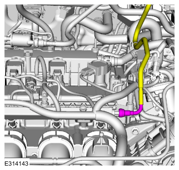
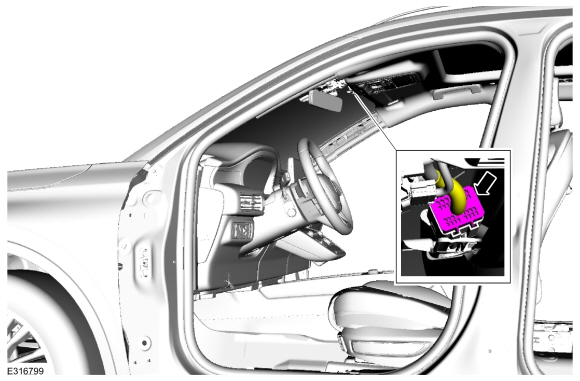
Disconnect the spring lock coupling.
Refer to: Spring Lock Couplings (310-00C Fuel System - General Information, General Procedures).
-
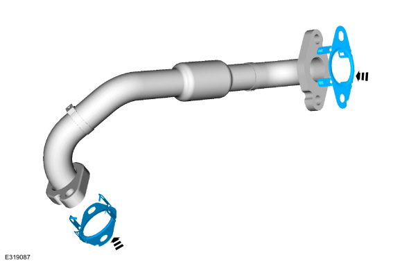
Remove the nuts, bolts and the EGR cooler inlet tube.
-
Discard the EGR cooler inlet tube gaskets.
-
-
Disconnect the HO2S electrical connector.
-
Remove the bolts and wire connector brackets.
-
Remove the HO2S .
Use Special Service Tool: 303-476
(T94P-9472-A)
Socket, Exhaust Gas Oxygen Sensor.
Material: Motorcraft® Penetrating and Lock Lubricant
/ XL-1
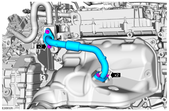
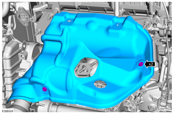
-
Remove the bolts and the exhaust manifold heat shield.
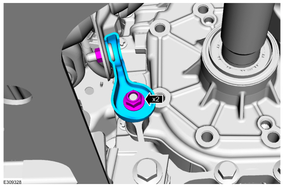
-
Remove the nuts and the bracket.
-
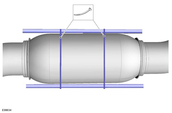
NOTICE:
Make sure that the exhaust flexible pipe is not forcibly bent or twisted.
Support the exhaust flexible pipe with a support wrap or suitable splint.
-
Remove the outlet clamp.
-
Make sure that the mating faces are clean and free of foreign material.
-
Remove the bolts for the exhaust manifold bracket.
-
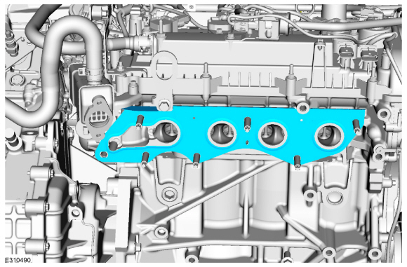
Remove and discard the nuts. Position back the exhaust manifold.
-
Remove and discard the exhaust manifold gasket.
-
Remove and discard the exhaust manifold studs.
-
Remove the following items:
-
Remove the air cleaner outlet pipe.
Refer to: Air Cleaner Outlet Pipe (303-12C Intake Air Distribution and Filtering, Removal and Installation).
-
Remove the intake manifold.
Refer to: Intake Manifold (303-01C Engine, Removal and Installation).
-
Remove the valve cover.
Refer to: Valve Cover (303-01C Engine, Removal and Installation).
-
Remove the camshafts.
Refer to: Camshafts (303-01C Engine, Removal and Installation).
-
Remove the ground wire.
-
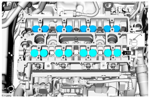
NOTE:
If the camshafts and valve tappets are to be reused,
mark the location of the valve tappets to make sure they are assembled
in their original positions.
NOTE:
The number on the valve tappets only reflects the
digits that follow the decimal. For example, a tappet with the number
0.650 has the thickness of 3.650 mm.
Remove the valve tappets.
-
Inspect the valve tappets.
-
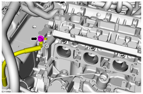
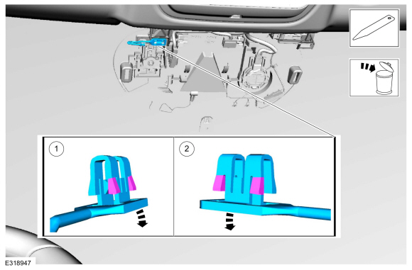
NOTICE:
Place absorbent towels under radiator hose to prevent coolant from contacting the ISC.
Disconnect the coolant hose.
Use the General Equipment: Hose Clamp Remover/Installer
-
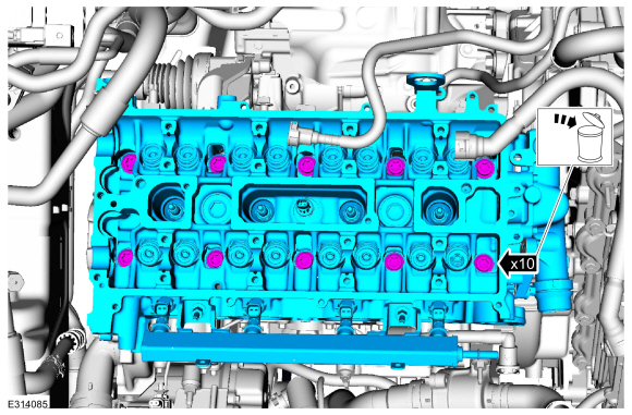
-
Remove the bolts and the cylinder head.
-
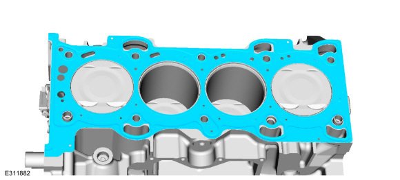
Remove and discard the cylinder head gasket.
Installation
-
NOTE:
Clean the cylinder block sealing surfaces.
Refer to: RTV Sealing Surface Cleaning and Preparation (303-00 Engine System - General Information, General Procedures).
-
NOTE:
Clean the cylinder head bolt holes in the cylinder
block. Make sure all coolant, oil or other foreign material is removed.
Clean the cylinder block sealing surfaces.
Refer to: RTV Sealing Surface Cleaning and Preparation (303-00 Engine System - General Information, General Procedures).
-
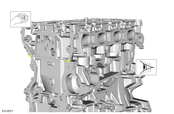
Check the cylinder head distortion.
Refer to: Cylinder Head Distortion (303-00 Engine System - General Information, General Procedures).
-
Check the cylinder block distortion.
Refer to: Cylinder Block Distortion (303-00 Engine System - General Information, General Procedures).
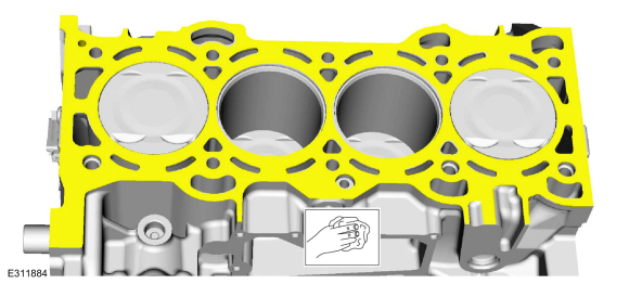
-
Apply a 6 mm bead of silicone sealant.
Material: Motorcraft® High Performance Engine RTV Silicone
/ TA-357
(WSE-M4G323-A6)
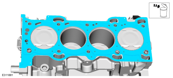
-
Install a new cylinder head gasket.
-
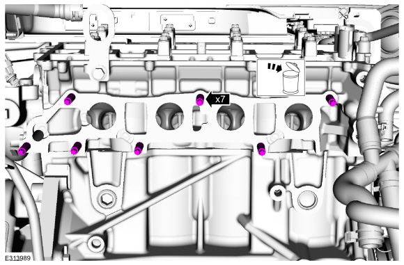
NOTE:
Discard the bolts.
Install the cylinder head and the bolts. Tighten in sequence shown in 5 stages.
Refer to: Specifications (303-01C Engine, Specifications).
Torque:
Stage 1:
62 lb.in (7 Nm)
Stage 2:
133 lb.in (15 Nm)
Stage 3:
33 lb.ft (45 Nm)
Stage 4:
90°
Stage 5:
90°
-
Remove excess sealer from the intersection of the cylinder block and cylinder head.
-
Connect the coolant hose.
Use the General Equipment: Hose Clamp Remover/Installer
-
NOTE:
Component(s) must be lubricated with clean engine oil.
Lubricate with clean engine oil and install the valve tappets.
Refer to: Specifications (303-01C Engine, Specifications).
-
Install the ground wire.
Torque:
133 lb.in (15 Nm)
-
Install the following items:
-
Install the camshafts.
Refer to: Camshafts (303-01C Engine, Removal and Installation).
-
Install the valve cover.
Refer to: Valve Cover (303-01C Engine, Removal and Installation).
-
Install the intake manifold.
Refer to: Intake Manifold (303-01C Engine, Removal and Installation).
-
Install the air cleaner outlet pipe.
Refer to: Air Cleaner Outlet Pipe (303-12C Intake Air Distribution and Filtering, Removal and Installation).
-
Install the new exhaust manifold studs.
Torque:
150 lb.in (17 Nm)
-
Install a new exhaust manifold gasket.
-
Install the exhaust manifold and new nuts.
Torque:
41 lb.ft (55 Nm)
-
Install the exhaust manifold bracket and bolts.
Torque:
18 lb.ft (25 Nm)
-
Install the outlet clamp.
Torque:
17 lb.ft (23 Nm)
-
Install the bracket and nuts.
Torque:
35 lb.ft (48 Nm)
-
NOTICE:
Make sure that the exhaust flexible pipe is not forcibly bent or twisted.
Remove the exhaust flexible pipe support.
-
Install the exhaust manifold heat shield and bolts.
Torque:
89 lb.in (10 Nm)
-
-
Calculate the correct torque wrench setting for the
following torque. Refer to Torque Wrench Adapter Formula in the Apex.
Install the HO2S .
Use Special Service Tool: 303-476
(T94P-9472-A)
Socket, Exhaust Gas Oxygen Sensor.
Material: Motorcraft® High Temperature Nickel Anti-Seize Lubricant
/ XL-2
Torque:
35 lb.ft (48 Nm)
-
Install the bolts and wire connector brackets.
-
Connect the HO2S electrical connector.
-
Clean and inspect the gasket surface and the studs. Replace the studs if necessary.
Torque:
159 lb.in (18 Nm)
-
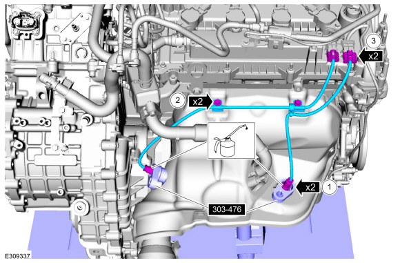
Install the new EGR cooler inlet tube gaskets.
-
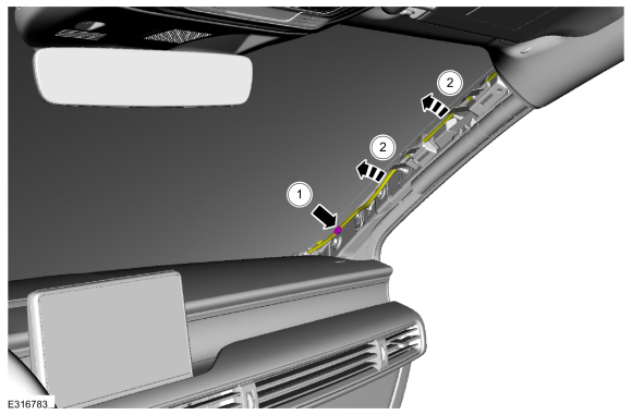
Install the EGR cooler inlet tube and install the fasteners hand tight.
-
Torque:
1:
89 lb.in (10 Nm)
2:
18 lb.ft (24 Nm)
1:
18 lb.ft (24 Nm)
3:
89 lb.in (10 Nm)
4:
18 lb.ft (24 Nm)
3:
18 lb.ft (24 Nm)
-
Connect the spring lock coupling.
Refer to: Spring Lock Couplings (310-00C Fuel System - General Information, General Procedures).
-
NOTE:
Component(s) must be lubricated with clean engine oil.
Install a new oil filter.
Refer to: Specifications (303-01C Engine, Specifications).
Torque:
Stage 1:
71 lb.in (8 Nm)
Stage 2:
180°
-
Fill the engine with clean engine oil.
Refer to: Specifications (303-01C Engine, Specifications).
-
Fill and bleed the cooling system.
Refer to: Engine Cooling System Draining, Vacuum Filling and Bleeding (303-03C Engine Cooling, General Procedures).
-
NOTE:
Use the Powertrain Control Module (PCM) Misfire
Monitor Profile Correction routine in the diagnostic scan tool.
-
Road test the vehicle.
Special Tool(s) /
General Equipment
Plastic Scraper
Trolley Jack
Materials
Name
Specification
Motorcraft® High Performance Engine RTV SiliconeTA-357
WSE-M4G323-A6
Motorcraft® Silicone Gasket RemoverZC-30-A, AZC-30-C
-
Motorcraft® Metal Surface Prep WipesZC-31-B
-
Motorcraft® Metal Brake Parts CleanerPM-4-A, PM-4-B, APM-4-C
-&nbs..
Other information:
Materials
Name
Specification
Motorcraft® Silicone Brake Caliper Grease and Dielectric CompoundXG-3-A
ESA-M1C200-AESE-M1C171-A
Motorcraft® Metal Brake Parts CleanerPM-4-A, PM-4-B, APM-4-C
-
Removal
WARNING:
Service actions on vehicles equipped with electronic brake
booster and electronic parking brakes may cause unexpected brake
application, wh..
Removal
Refer to: Accessory Drive Belt - Vehicles Built Up To: 1-October-2020
(303-05A Accessory Drive - 1.5L EcoBoost (132kW/180PS) – I3 (Y1),
Removal and Installation).
Loosen the bolt and remove the accessory drive belt idler pulley.
Torque:
18 lb.ft (25 Nm)
Installation
To install, reverse the removal procedure.
..
.jpg)
.jpg)
.jpg)

.jpg)
.jpg)
.jpg)
.jpg)
.jpg)
.jpg)
.jpg)
.jpg)

 Removal and Installation - Engine Front Cover