Ford Escape 2020-2026 Service Manual / Body and Paint / Body and Paint / Front Seats / Removal and Installation - Front Seat
Ford Escape: Front Seats / Removal and Installation - Front Seat
Removal
.jpg) WARNING:
The following procedure describes critical repair steps
required for correct seat component installation. Follow all notes and
steps carefully. Do not place any objects between the seat components
and the body of the vehicle, nor any objects within a joint internal to
the seat structure. Failure to follow step instructions may result in
incorrect operation of the seat components and increases the risk of
serious personal injury.
WARNING:
The following procedure describes critical repair steps
required for correct seat component installation. Follow all notes and
steps carefully. Do not place any objects between the seat components
and the body of the vehicle, nor any objects within a joint internal to
the seat structure. Failure to follow step instructions may result in
incorrect operation of the seat components and increases the risk of
serious personal injury.
NOTE: Driver seat shown, passenger seat similar.
NOTE: Removal steps in this procedure may contain installation details.
-
Move the front seat to the full upward position and forward or rearward to access all of the seat bolts.
.jpg) |
-
.
Depower the SRS
Refer to: Supplemental Restraint System (SRS) Depowering (501-20B Supplemental Restraint System, General Procedures).
-
Disconnect the front seat harness electrical connector.
-
Detach the wiring harness retainer.
-
Disconnect the electrical connector.
-
Detach the wiring harness retainer.
.jpg) |
-
Remove the front seat bolt covers.
.jpg) |
-
NOTE: Follow the unique instructions or graphics for this step in the installation.
Remove the front seat.
-
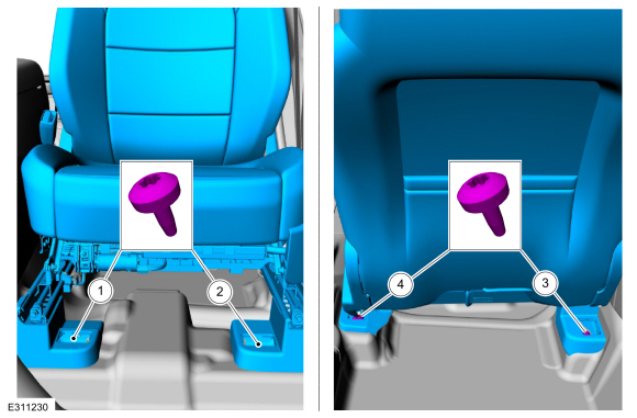
Remove and discard the seat bolts.
-
Remove and discard the seat bolts.
.jpg) |
Installation
-
To install, reverse the removal procedure.
-
Install the front seat bolts in the following sequence.
-
Install the front inboard bolt.
Torque: 30 lb.ft (40 Nm)
-
Install the front outboard bolt.
Torque: 30 lb.ft (40 Nm)
-
Install the rear inboard bolt.
Torque: 30 lb.ft (40 Nm)
-
Install the rear outboard bolt.
Torque: 30 lb.ft (40 Nm)
-
Install the front inboard bolt.
 |
-
Repower the SRS .
Refer to: Supplemental Restraint System (SRS) Repowering (501-20B Supplemental Restraint System, General Procedures).
 Removal and Installation - Front Head Restraint Guide Sleeve
Special Tool(s) /
General Equipment
Flat-Bladed Screwdriver
Removal
NOTE:
Driver seat shown, passenger seat similar.
Remove the front head restraint...
 Removal and Installation - Front Seat Backrest
Removal
WARNING:
The following procedure describes critical repair steps
required for correct seat component installation. Follow all notes and
steps carefully...
Other information:
Ford Escape 2020-2026 Owners Manual: Fuel Quality
Selecting the Correct Fuel Choosing the Right Fuel Your vehicle operates on regular unleaded gasoline with a minimum pump (R+M)/2 octane rating of 87. Some fuel stations, particularly those in high altitude areas, offer fuels posted as regular unleaded gasoline with an octane rating below 87...
Ford Escape 2020-2026 Owners Manual: Emission Law
WARNING: Do not remove or alter the original equipment floor covering or insulation between it and the metal floor of the vehicle. The floor covering and insulation protect occupants of the vehicle from the engine and exhaust system heat and noise...
Categories
- Manuals Home
- 4th Generation Ford Escape Owners Manual
- 4th Generation Ford Escape Service Manual
- Power Outlet - Vehicles With: 12V Power Outlet
- Locating the Pre-Collision Assist Sensors
- Switching the Lane Keeping System On and Off. Switching the Lane Keeping System Mode. Alert Mode
- New on site
- Most important about car
Engine Oil
Engine Oil Dipstick Overview

Copyright © 2026 www.fordescape4.com