Ford Escape: Uni-Body, Subframe and Mounting System / Removal and Installation - Front Subframe
Special Tool(s) /
General Equipment
| Tie Rod End Remover |
| Transmission Jack |
Materials
| Name |
Specification |
Motorcraft® Metal Brake Parts Cleaner
PM-4-A, PM-4-B, APM-4-C |
-
|
Removal
-
NOTICE:
Disconnect the battery ground cable anytime the
steering gear is being serviced or damage to the steering gear internal
power relay may occur resulting in steering gear replacement.
Disconnect the battery ground cable.
Refer to: Battery Disconnect and Connect (414-01 Battery, Mounting and Cables, General Procedures).
-
Steering wheel in straight ahead position.
-
 WARNING:
Do not reuse steering column shaft bolts. This may
result in fastener failure and steering column shaft detachment or loss
of steering control. Failure to follow this instruction may result in
serious injury to vehicle occupant(s).
WARNING:
Do not reuse steering column shaft bolts. This may
result in fastener failure and steering column shaft detachment or loss
of steering control. Failure to follow this instruction may result in
serious injury to vehicle occupant(s).
Remove and discard the steering column shaft coupler bolt and separate the coupler from the steering shaft.
-
Remove the wheels and tires.
Refer to: Wheel and Tire (204-04A Wheels and Tires, Removal and Installation).
-
Remove the fender splash shield.
Refer to: Fender Splash Shield (501-02 Front End Body Panels, Removal and Installation).
-
Remove the bolts and the underbody shields.
-
Remove the retainers and the underbody shields.
-
Remove the retainers and the underbody shields.
-
Remove front bumper cover.
Refer to: Front Bumper Cover (501-19 Bumpers, Removal and Installation).
-
Remove the subframe support bracket bolts.
-
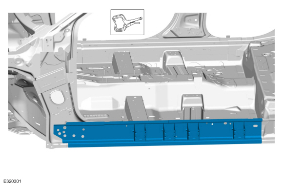
On both sides.
Remove and discard the bolts and remove the front outer side member.
-
NOTE:
The stabilizer bar links are designed with low friction ball joints that have a low breakaway torque.
NOTE:
Use the hex-holding feature to prevent the ball stud
from turning while removing or installing the stabilizer bar link nut.
On both sides.
Remove and discard the stabilizer bar link lower nut and position aside the stabilizer bar link.
-
NOTICE:
Do not use a hammer to separate the outer tie-rod
end from the wheel knuckle or damage to the wheel knuckle may result.
NOTICE:
Use care when installing the tie rod separator or damage to the outer tie-rod end boot may occur.
On both sides.
Remove and discard the tie rod end nut and separate the tie rod end from the wheel knuckle.
Use the General Equipment: Tie Rod End Remover
.jpg) |
|
-
NOTICE:
Do not use a prying device to open the slot in the
knuckle to separate the lower ball joint from the knuckle assembly.
Damage to the knuckle assembly may occur.
NOTICE:
Do not use a prying device or separator fork between
the ball joint and the wheel knuckle. Damage to the ball joint or ball
joint seal may result. Only use the pry bar by inserting it into the
lower arm body opening.
NOTICE:
Use care when releasing the lower arm and wheel
knuckle into the resting position or damage to the ball joint seal may
occur.
On both sides.
Remove and discard the ball joint pinch bolt and nut and separate the ball joint from the wheel knuckle.
-
NOTICE:
Do not excessively bend or twist the exhaust
flexible pipe. Failure to follow these instructions may cause damage to
the exhaust flexible pipe.
Secure the exhaust flexible pipe.
-
Remove the exhaust support bracket bolts.
-
NOTE:
2.0L GTDI shown, others similar.
Remove and discard the roll restrictor bolt.
-
If equipped.
Unclip the wire harness retainers.
-
If equipped.
Unclip the wire harness retainers.
-
Position a transmission jack under the front subframe.
Use the General Equipment: Transmission Jack
-
NOTE:
Rear mounting location shown.
On both sides.
Index-mark the subframe to the body.
-
NOTE:
Front mounting location shown.
On both sides.
Index-mark the subframe to the body.
-
-
Remove and discard the rearward subframe bolts.
-
Remove and discard the bolts and remove the subframe brackets.
-
On both sides.
Remove and discard the forward subframe bolts.
-
NOTE:
Make sure that no components catch.
Lower the subframe.
Use the General Equipment: Transmission Jack
-
NOTICE:
The steering column floor seal is a one time use
seal and must be replaced anytime that the front subframe is lowered or
separated from the vehicle.
NOTE:
Note the position of the component before removal.
Remove and discard the steering column floor seal.
Installation
-
NOTE:
The steering column floor seal mounting surface must be cleaned using solvent before reinstallation.
Clean and inspect the steering column floor seal mounting surface before reinstallation.
Material: Motorcraft® Metal Brake Parts Cleaner
/ PM-4-A, PM-4-B, APM-4-C
-
NOTE:
Make sure that the floor seal lip is fully wrapped around the carrier on the steering gear.
Install the new steering column floor seal.
-
Partially raise the subframe and position it to the vehicle.
Use the General Equipment: Transmission Jack
-
On both sides.
Install the new forward subframe bolts finger tight.
-
-
Install the subframe brackets and the new rearward subframe bolts finger tight.
-
Install the new subframe bracket bolts finger tight.
-
NOTE:
Rear mounting location shown.
On both sides.
Align index-mark made during removal.
-
NOTE:
Front mounting location shown.
On both sides.
Align index-mark made during removal.
-
On both sides.
Tighten the forward subframe bolts.
Torque:
85 lb.ft (115 Nm)
-
-
Tighten the bolts.
Torque:
Stage 1:
159 lb.ft (215 Nm)
Stage 2:
120°
-
Tighten the bolts.
Torque:
46 lb.ft (63 Nm)
-
If equipped.
Clip the wire harness retainers.
-
If equipped.
Clip the wire harness retainers.
-
NOTE:
2.0L GTDI shown, others similar.
Install the new roll restrictor bolt.
Torque:
129 lb.ft (175 Nm)
-
Install the exhaust support bracket bolts.
Torque:
18 lb.ft (25 Nm)
-
Release the exhaust flexible pipe support.
-
On both sides.
Connect the lower ball joint to the wheel knuckle and install the new ball joint pinch bolt and nut.
Torque:
66 lb.ft (90 Nm)
-
NOTE:
Use the hex-holding feature to prevent the component from turning.
On both sides.
Connect the tie rod end to the wheel knuckle and install the new tie rod end nut.
Torque:
35 lb.ft (48 Nm)
-
NOTE:
Use the hex-holding feature to prevent the component from turning.
On both sides.
Position the stabilizer bar links and install the new stabilizer bar link lower nut.
Torque:
85 lb.ft (115 Nm)
-
On both sides.
Install the front outer side member with new bolts.
Torque:
30 lb.ft (40 Nm)
-
Install the subframe support bracket bolts.
Torque:
22 lb.ft (30 Nm)
-
Install the front bumper cover.
Refer to: Front Bumper Cover (501-19 Bumpers, Removal and Installation).
-
Install the underbody shield and the retainers.
Torque:
22 lb.in (2.5 Nm)
-
Install the underbody shields and the retainers.
Torque:
22 lb.in (2.5 Nm)
-
Position the steering shaft coupler and install the new steering shaft coupler bolt.
Torque:
46 lb.ft (63 Nm)
-
Remove the holding device.
-
Install the underbody shield and the retainers.
Torque:
13 lb.in (1.5 Nm)
-
Install the fender splash shield.
Refer to: Fender Splash Shield (501-02 Front End Body Panels, Removal and Installation).
-
Install the wheels and tires.
Refer to: Wheel and Tire (204-04A Wheels and Tires, Removal and Installation).
-
Connect the battery ground cable.
Refer to: Battery Disconnect and Connect (414-01 Battery, Mounting and Cables, General Procedures).
-
Check and if necessary adjust front toe.
Refer to: Front Toe Adjustment (204-00 Suspension System - General Information, General Procedures).
Special Tool(s) /
General Equipment
205-1075Remover/Installer, Rear Drive Unit Front
Removal
Front bushings
NOTE:
LH shown, RH similar...
Other information:
Overview
The ACC cruise control system is controlled by the PCM , CCM and IPMA .
The ACC cruise control modes are selected from the steering wheel
mounted switches, which are integrated into the LH steering wheel
switch.
The cruise control icons on the steering wheel switch change depending on option:
Base cruise control...
Special Tool(s) /
General Equipment
Power Caulk Gun
Power Fixed Glass Removal Tool
Vacuum Cleaner
Materials
Name
Specification
Motorcraft® High Performance Engine RTV SiliconeTA-357
WSE-M4G323-A6
Sika® SikaTack® MACH 60 / Sika® SikaTack® MACH 30 / Dow® BETASEAL™ Express
-
Sika® Aktivator PRO / Dow® BETAPRIME™ 5504G / Sika® Primer..
Categories
What Is the Master Access Code
The master access code is a factory-set
five-digit entry code. You can operate the
keypad with the master access code at
any time. The master access code is on the
owner’s wallet card in the glove box and
is available from an authorized dealer.
Displaying the Master Access Code
To display the factory-set code in the
information display:

Remove the rubber mat.
Insert the first programmed key in the
backup slot.
Press the push button ignition switch
once and wait a few seconds.
Press the push button ignition switch
again and remove the key.
Within 10 seconds, place a second
programmed intelligent access key in
the backup slot and press the push
button ignition switch.
read more
.jpg)
.jpg)
.jpg)
.jpg)
.jpg)
.jpg)
.jpg)
.jpg)
.jpg)
.jpg)
.jpg)
.jpg)
.jpg)
.jpg)
.jpg)
.jpg)
.jpg)
.jpg)
.jpg)
.jpg)
.jpg)
.jpg)
.jpg)
.jpg)
.jpg)
.jpg)
.jpg)
.jpg)
.jpg)
.jpg)
.jpg)
.jpg)
.jpg)
.jpg)
.jpg)

 Removal and Installation - Rear Differential Subframe Bushings