Ford Escape: Evaporative Emissions / Removal and Installation - Fuel Tank Pressure Sensor and Tube - Hybrid Electric Vehicle (HEV)
Removal
.jpg) WARNING:
Do not smoke, carry lighted tobacco or have an open flame of
any type when working on or near any fuel-related component. Highly
flammable mixtures may be present and may be ignited. Failure to follow
these instructions may result in serious personal injury.
WARNING:
Do not smoke, carry lighted tobacco or have an open flame of
any type when working on or near any fuel-related component. Highly
flammable mixtures may be present and may be ignited. Failure to follow
these instructions may result in serious personal injury.
.jpg) WARNING:
Do not carry personal electronic devices such as cell
phones, pagers or audio equipment of any type when working on or near
any fuel-related component. Highly flammable mixtures may be present and
may be ignited. Failure to follow these instructions may result in
serious personal injury.
WARNING:
Do not carry personal electronic devices such as cell
phones, pagers or audio equipment of any type when working on or near
any fuel-related component. Highly flammable mixtures may be present and
may be ignited. Failure to follow these instructions may result in
serious personal injury.
.jpg) WARNING:
Always disconnect the battery ground cable at the battery
when working on an evaporative emission (EVAP) system or fuel-related
component. Highly flammable mixtures may be present and may be ignited.
Failure to follow these instructions may result in serious personal
injury.
WARNING:
Always disconnect the battery ground cable at the battery
when working on an evaporative emission (EVAP) system or fuel-related
component. Highly flammable mixtures may be present and may be ignited.
Failure to follow these instructions may result in serious personal
injury.
NOTE: Removal steps in this procedure may contain installation steps.
-
With the vehicle in NEUTRAL, position it on a hoist.
Refer to: Jacking and Lifting (100-02 Jacking and Lifting - 2.5L Duratec – Hybrid (121kW/164PS) (BG)) .
-
Disconnect the negative battery cable.
Refer to: Battery Disconnect and Connect - Full Hybrid Electric Vehicle (FHEV)/Plug-In Hybrid Electric Vehicle (PHEV) (414-01) .
-
-
Remove the fasteners.
Torque: 22 lb.in (2.5 Nm)
-
Remove the fasteners.
Torque: 22 lb.in (2.5 Nm)
-
Remove the pushpins.
-
Remove the fasteners.
.jpg) |
-
Disconnect the electrical connector.
.jpg) |
-
Disconnect the quick release couplings and remove the fuel tank pressure sensor and tube.
Refer to: Quick Release Coupling (310-00 Fuel System - General Information - 2.5L Duratec – Hybrid (121kW/164PS) (BG)) .
.jpg) |
Installation
-
To install, reverse the removal procedure.
 Removal and Installation - Fuel Tank Pressure Sensor and Tube - Plug-In Hybrid Electric Vehicle (PHEV)
Removal
WARNING:
Do not smoke, carry lighted tobacco or have an open flame of
any type when working on or near any fuel-related component...
 Removal and Installation - Fuel Vapor Vent Valve - Plug-In Hybrid Electric Vehicle (PHEV)
Removal
WARNING:
Do not smoke, carry lighted tobacco or have an open flame of
any type when working on or near any fuel-related component...
Other information:
Ford Escape 2020-2024 Service Manual: Removal and Installation - Front Fog Lamp
Removal Remove the front bumper cover. Refer to: Front Bumper Cover (501-19 Bumpers, Removal and Installation). Remove the front fog lamp. Detach the front fog lamp wire harness retainer. Disconnect the front fog lamp electrical connector...
Ford Escape 2020-2024 Owners Manual: Changing the Format of the Map
Display the map in one of the following formats: A two-dimensional map with the direction you are traveling toward the top of the screen. A two-dimensional map with north toward the top of the screen. A three-dimensional map with the direction you are traveling toward the front...
Categories
- Manuals Home
- 4th Generation Ford Escape Owners Manual
- 4th Generation Ford Escape Service Manual
- All-Wheel Drive
- Opening and Closing the Hood
- Traction Control
- New on site
- Most important about car
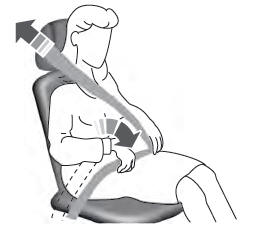
Adjusting the Seatbelts During Pregnancy
WARNING: Always ride and drive with your seatback upright and properly fasten your seatbelt. Fit the lap portion of the seatbelt snugly and low across the hips. Position the shoulder portion of the seatbelt across your chest. Pregnant women must follow this practice. See the following figure.

