Ford Escape: Uni-Body, Subframe and Mounting System / Removal and Installation - Rear Subframe
Special Tool(s) / General Equipment
.jpg) |
300-OTC1585AE Powertrain Lift |
| Wooden Block | |
Removal
NOTICE: Suspension fasteners are critical parts that affect the performance of vital components and systems. Failure of these fasteners may result in major service expense. Use the same or equivalent parts if replacement is necessary. Do not use a replacement part of lesser quality or substitute design. Tighten fasteners as specified.
All vehicles
-
Remove the wheels and tire.
Refer to: Wheel and Tire (204-04A Wheels and Tires, Removal and Installation).
-
On both sides.
Remove the rear stabilizer link.
Refer to: Rear Stabilizer Bar Link (204-02 Rear Suspension, Removal and Installation).
-
Remove the muffler and tail pipe.
Refer to: Muffler and Tailpipe (309-00A Exhaust System - 1.5L EcoBoost (132kW/180PS) – I3 (Y1), Removal and Installation).
Refer to: Muffler and Tailpipe - 4WD (309-00A Exhaust System - 1.5L EcoBoost (132kW/180PS) – I3 (Y1), Removal and Installation).
Refer to: Muffler and Tailpipe (309-00B Exhaust System - 2.0L EcoBoost (177kW/240PS) – MI4, Removal and Installation).
Refer to: Muffler and Tailpipe (309-00E) .
-
On both sides.
Remove the springs.
Refer to: Spring (204-02 Rear Suspension, Removal and Installation).
-
On both sides.
Remove and discard the upper arm-to-wheel knuckle bolt.
.jpg) |
-
On both sides.
Remove and discard the front lower arm-to-wheel knuckle bolt.
.jpg) |
-
Remove fasteners and the underbody shield.
.jpg) |
-
Disconnect the electrical connector and wire retainers.
.jpg) |
All wheel drive (AWD) vehicles
-
Remove the rear driveshaft.
Refer to: Rear Driveshaft (205-01 Driveshaft, Removal and Installation).
-
On both sides.
Remove the rear halfshaft.
Refer to: Rear Halfshaft (205-05 Rear Drive Halfshafts, Removal and Installation).
-
-
Disconnect the vent hose.
-
Remove the bolt.
-
Disconnect the vent hose.
.jpg) |
-
Remove the hose retainers and position aside the vent hose from rear subframe.
.jpg) |
All vehicles
-
NOTE: Rear mounting location shown.
On both sides
Index-mark the subframe to the body.
.jpg) |
-
NOTE: Front mounting location shown.
On both sides
Index-mark the subframe to the body.
.jpg) |
-
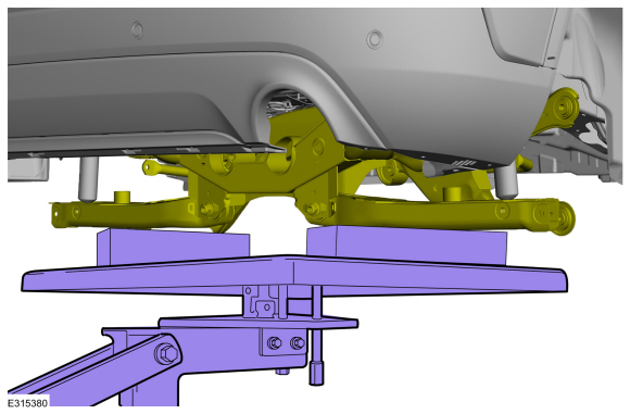
NOTE: FWD shown AWD similar.
Position a transmission jack under the rear subframe.
Use Special Service Tool: 300-OTC1585AE Powertrain Lift.
Use the General Equipment: Wooden Block
 |
-
NOTE: FWD shown AWD similar.
Remove and discard the rear subframe bolts.
.jpg) |
-
NOTE: Make sure that no components catch.
NOTE: FWD shown AWD similar.
Lower the rear subframe.
Use Special Service Tool: 300-OTC1585AE Powertrain Lift.
Use the General Equipment: Wooden Block
.jpg) |
Installation
All vehicles
-
NOTE: FWD shown AWD similar.
Raise the rear subframe and position it to the vehicle.
Use Special Service Tool: 300-OTC1585AE Powertrain Lift.
Use the General Equipment: Wooden Block
.jpg) |
-
NOTE: Rear mounting location shown.
On both sides
Align index-mark made during removal.
.jpg) |
-
NOTE: Front mounting location shown.
On both sides
Align index-mark made during removal.
.jpg) |
-
NOTE: FWD shown AWD similar.
Install the bolts.
Torque: 85 lb.ft (115 Nm)
.jpg) |
All wheel drive (AWD) vehicles
-
Remove the hose retainers and position aside the vent hose from rear subframe.
|
-
-
Connect the vent hose.
-
Install the bolt.
Torque: 106 lb.in (12 Nm)
-
Connect the vent hose.
.jpg) |
-
On both sides.
Install the rear halfshaft.
Refer to: Rear Halfshaft (205-05 Rear Drive Halfshafts, Removal and Installation).
-
Install the rear driveshaft.
Refer to: Rear Driveshaft (205-01 Driveshaft, Removal and Installation).
All vehicles
-
Connect the electrical connector and wire retainer.
|
-
Install the underbody shield and the fasteners.
Torque: 17 lb.in (1.9 Nm)
|
-
NOTE: Finger tight only at this stage.
On both sides.
Install the new front lower arm-to-wheel knuckle bolt.
.jpg) |
-
NOTE: Finger tight only at this stage.
On both sides.
Install the new upper arm-to-wheel knuckle bolt.
.jpg) |
-
On both sides.
Install the rear spring.
Refer to: Spring (204-02 Rear Suspension, Removal and Installation).
-
NOTICE: Tighten the suspension bushing fasteners with the suspension loaded or with the weight of the vehicle resting on the wheels and tires, or incorrect clamp load and bushing damage may occur.
On both sides.
Tighten the front lower arm-to-wheel knuckle bolt.
Torque: 85 lb.ft (115 Nm)
|
-
NOTICE: Tighten the suspension bushing fasteners with the suspension loaded or with the weight of the vehicle resting on the wheels and tires, or incorrect clamp load and bushing damage may occur.
On both sides.
Tighten the upper arm-to-wheel knuckle bolt.
Torque: 85 lb.ft (115 Nm)
|
-
On both sides. Install the rear stabilizer bar link.
Refer to: Rear Stabilizer Bar Link (204-02 Rear Suspension, Removal and Installation).
-
Install the muffler and tail pipe.
Refer to: Muffler and Tailpipe (309-00A Exhaust System - 1.5L EcoBoost (132kW/180PS) – I3 (Y1), Removal and Installation).
Refer to: Muffler and Tailpipe - 4WD (309-00A Exhaust System - 1.5L EcoBoost (132kW/180PS) – I3 (Y1), Removal and Installation).
Refer to: Muffler and Tailpipe (309-00B Exhaust System - 2.0L EcoBoost (177kW/240PS) – MI4, Removal and Installation).
Refer to: Muffler and Tailpipe (309-00E) .
-
Install the wheels and tires.
Refer to: Wheel and Tire (204-04A Wheels and Tires, Removal and Installation).
-
Check and, if necessary, adjust rear toe.
Refer to: Rear Toe Adjustment (204-00 Suspension System - General Information, General Procedures).
 Removal and Installation - Rear Differential Subframe Bushings
Special Tool(s) /
General Equipment
205-1075Remover/Installer, Rear Drive Unit Front
Removal
Front bushings
NOTE:
LH shown, RH similar...
 Removal and Installation - Rear Subframe Front Bushing
Special Tool(s) /
General Equipment
204-598Hydraulic Cylinder 10t
204-598-01Remover/Installer, Subframe Bushing Guide
204-598-04Adapter for 204-598
204-598-05Adapter for 204-598
Removal
NOTE:
Removal steps in this procedure may contain installation details...
Other information:
Ford Escape 2020-2026 Service Manual: Description and Operation - Parking Aid - System Operation and Component Description
System Operation Active Park Assist System Diagram Item Description 1 Rear door speakers 2 Front door speakers 3 Audio system display 4 TRM 5 BCM 6 PCM 7 ABS module 8 DSP 9 ACM 10 IPC 11 APIM 12 PSCM 13 with 10 speaker system 14 GWM 15 S..
Ford Escape 2020-2026 Service Manual: Removal and Installation - Light Emitting Diode (LED) Control Module
Removal NOTE: Removal steps in this procedure may contain installation details. Remove the headlamp assembly. Refer to: Headlamp Assembly (417-01 Exterior Lighting, Removal and Installation). Remove the screws and position the lower LED control module. Disconnect the electrical connectors and remove the lower LED control module. ..
Categories
- Manuals Home
- 4th Generation Ford Escape Owners Manual
- 4th Generation Ford Escape Service Manual
- Opening and Closing the Hood
- Electric Parking Brake
- Symbols Glossary
- New on site
- Most important about car
Vehicle Identification
Locating the Vehicle Identification Number
The vehicle identification number is on the left-hand side of the instrument panel.
